You must be logged in to rate content!
31 minute read
Side to Top Feed Conversion
Compliments of SoloWRXSTi @ www.iwsti.com
1-29-2012
I wanted to write a DIY for those looking to convert from side feed injectors to top feed. I’ve pinpointed some misfire issues to a specific injector, and decided to do the conversion, delete the TGVs, and put in some ID 1000cc injectors so I can run E85 in the summer.
Advantages:
Top feed injectors are more common, thus usually cheaper
Opportunity to delete TGVs
Top feed injectors come in larger flow rates to allow use of E85 in high HP cars
Disadvantages
Semi-permanent modifications needed (trimming of brackets)
Top feed injectors are more difficult to access when installed in the car
Here is a list of items you will need in order to complete the conversion.
Top feed fuel rails – I have fuel rails from a WRX. You can also use aftermarket ones, consult the install guide that came with your rails when you get to the rail swap section.
Top feed TGVs – I also had some from a WRX. I decided to delete the butterflys inside myself. Consult the other How-To or buy some that are already deleted.
Top feed fuel injectors – I decided to buy a set of ID 1000cc injectors, but you can choose whichever ones you’d like. Just be sure they are top feed.
Top feed wiring harnesses – The wiring harness is different between a side feed and a top feed injector. Injector Dynamics makes plug-n-play conversion harnesses, or if you buy a set of their injectors, they supply the harness pins/shells to convert. However, it requires the use of a special pin crimper which is as much as the conversion harnesses are, so I decided to go the plug-n-play route.
Engine Management – I say this because your new injectors will probably have different electrical characteristics (latency, type, etc) that will need to be accounted for in your tune. Also, since it would be advisable to delete the TGVs, your resulting DTCs will need to be disabled. I am using a COBB AP on my 05 STI.
Gaskets 14035AA421 (x2) and 14075AA161 (x2) – These are the gaskets that go between the intake manifold and the TGV, as well as the TGV to cylinder head. You need 2 each (one per side).
Vacuum hose - The fuel pressure regulators are in different places on a top and side feed fuel rail, so you will need to get a longer piece of tubing to connect it to the vacuum/boost source. I bought 2 feet of 1/8" I.D. line.
Cutoff wheel - There is some minor fabrication involved in doing the conversion. A cutoff wheel is need to trim some brackets for fitment.
Subaru Coolant and Distilled Water (or get Subaru Pre-Mix) - You will be draining some of the coolant system, so I replenished it with new Subaru coolant. Go to the dealership and get the RIGHT stuff, don't go to Auto-Zone and get Prestone or Peak. This is WRONG!
Fuel Pump (optional) – I decided to upgrade the fuel pump to an Aeromotive 340 lph drop-in since I’ll be running E85. Since most of you will be going with bigger injectors in this conversion, I recommend a bigger fuel pump.
Total Time – I would allocate at least one day, but could be longer/shorter, depending upon your experience. This took me two, ¾ days to complete (including welding the TGVs)
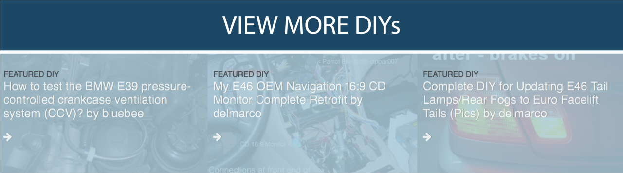
Step 1 – - Disconnect Fuel Pump Relay – You will be working with fuel, so you need to release the pressure in the supply line. Underneath the glove box on the right side, you will see three relays just above the carpet. The fuel pump relay is the one with a 4-pin green connector. Disconnect it.
Step 2 – Release Fuel Pressure – Get in the driver’s seat and crank over the engine for about 10 seconds. My car never fired, but if yours does, let it run until it dies.
Step 3 – Open filler cap – Ensures no pressure is built up inside the gas tank.
Step 4 – Remove the Battery – Using a 10mm socket, disconnect the positive and negative terminals. Then, remove the two nuts holding down the battery and remove the tie-down, battery, battery tray, and tie down rods.
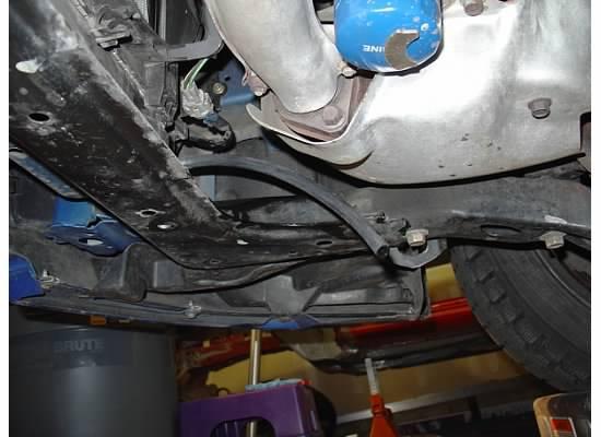
Step 5 – Remove undertray – Gives you access to the radiator drain plug.
Step 6 - Drain approximately 3 liters of coolant - Draining the upper parts of the cooling system allows you to remove the coolant fill tank, lines, and throttle body (yes, coolant runs through your throttle body) without spills. Turn the drain valve a few turns until coolant starts coming out into a pan. Ensure that both coolant pressure caps are removed so that air can enter the system to displace the coolant.
Step 7 - Remove airbox - Disconnect the MAF sensor. Remove the coolant lines going to the coolant tank that are attached to the airbox lid. Using a 8mm nut driver, loosen the hose clamp that connects to the turbo inlet. Snap both hold-downs off, and remove the lid. Take a 12" extension with a 12mm socket, remove the two bolts holding the lower airbox to the frame. Remove the lower airbox. I suggest removing the rubber grommet that engages with the airbox alignment pin and install it with the airbox. If you leave it on the car, you can accidentally push it behind the fender, and then a search-and-rescue is on.
Step 8 - Remove intercooler – First, remove the two 12mm bolts from the bypass valve. Next, remove the two 12mm bolts that attach the intercooler to the engine brackets. Next, using a 8mm nut driver, loosen the clamp on the throttle body hose coupler (I like the front one). Next, loosen the clamp holding the charge coupler to the turbine outlet. Finally, disconnect the crossover pipes from the breather tubes (two on passenger side, one on driver side). You should be able to remove the intercooler, pulling in the driver’s side direction.
Step 9 – Remove coolant tank – There are four hoses attached to the coolant tank: the pair that come from the radiator (over the airbox lid), one in the rear and one on the bottom. The one on the bottom is the most difficult. First, loosen the two 12mm bolts on top of the tank, and one 12mm nut on the side. Next, remove the four hoses and finally, remove the tank.
Step 10 – Remove belt cover – One 10mm bolt and one 10mm nut hold the cover down.
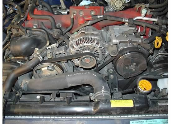
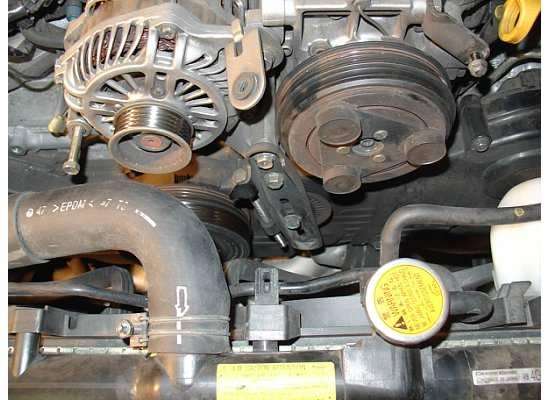
Step 11 – Remove V-belt – You will need to remove the other belt later, but for now, just remove the front one. Loosen the 12mm set bolt that attaches to the alternator, then loosen the 12mm tension bolt until you can remove the belt. My STI has 62k miles on it, and the belt was in poor condition. I recommend replacing it if yours is in the same state.
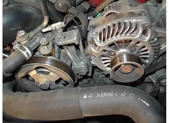
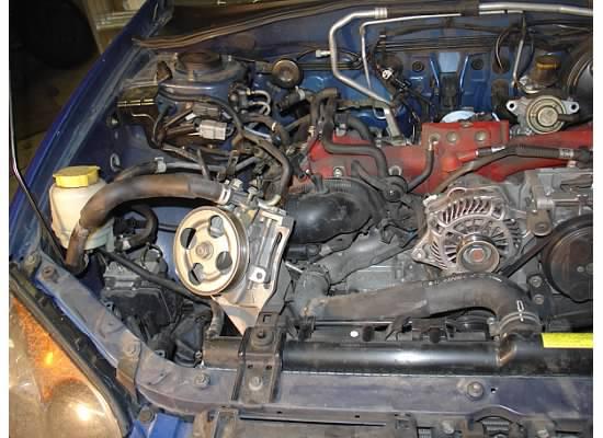
Step 12 – Disconnect the power steering pump wire – You will be moving the power steering pump, so this wire needs to be disconnected.
Step 13 – Disconnect power steering lines from intake manifold bracket – There are three 10mm bolts that hold the two power steering lines to the intake manifold bracket. Remove them so that the lines are free from the engine.
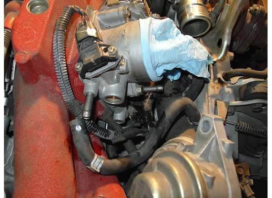
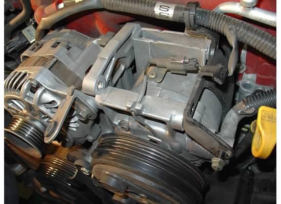
Step 14 – Remove the purge valve control solenoid – This is the rectangular box that sits behind the power steering pump and is connected to the intake manifold by one 12mm bolt. Remove the bolt and let the solenoid “dangle”, so you have easier access to the tough bolt you need to remove in the next step.
Step 15 – Remove power steering pump and lay on side – You will need to put the power steering pump out of the way, so remove the three 12mm bolts that attach the pump to the engine block. One is below the purge valve solenoid (the hard one, use a universal joint and a long extension), and the other two are on the underside of the pump. The longer bolt is on the driver side, in case you get them mixed up. Finally, removing the power steering fluid reservoir from the bracket will help is moving everything to the void where the airbox was.
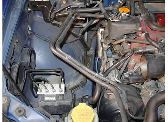
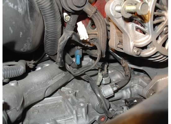
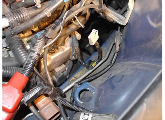
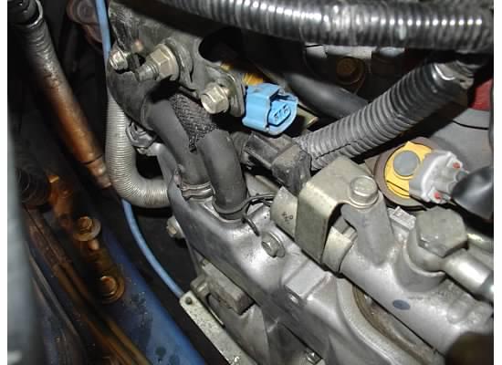
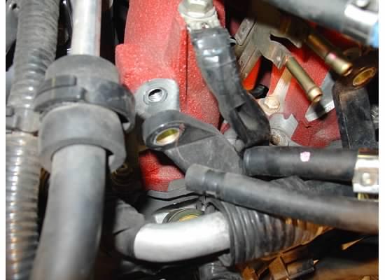
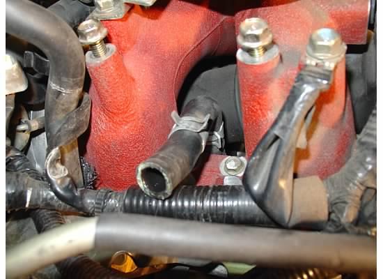
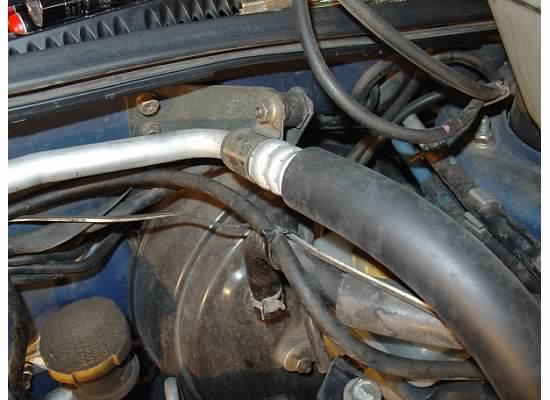
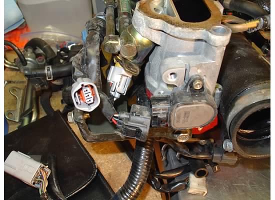
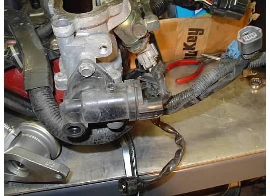
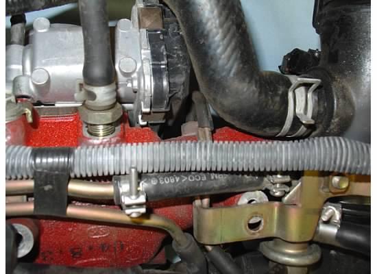
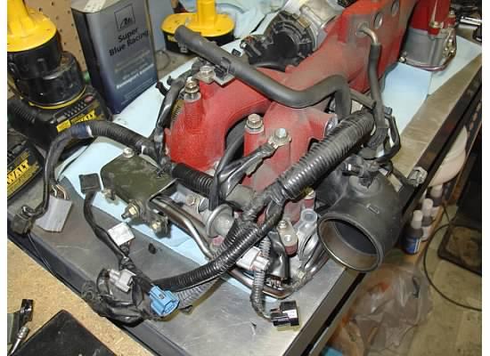
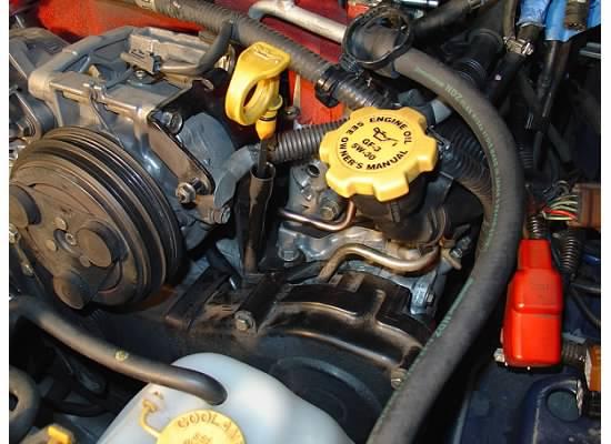
Step 16 – Disconnect PCV wires/hose – Disconnect the PCV wires that is next to the turbo and throttle body (gray connector). You will also need to disconnect the PCV hose that is connected to the tee at the PCV. You can see the barb where the hose was connected in the second picture.
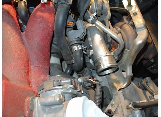
Step 17 – Disconnect throttle body coolant hoses – This still puzzles me as to why coolant lines run to your throttle body, but they do. One hose is on the top side pointing to the driver side fender, the other is on the bottom pointing aft. Disconnect both.
Step 18 – Disconnect brake booster hose – This hose is a large hose that is on the driver side of the intake manifold below the intercooler bracket.
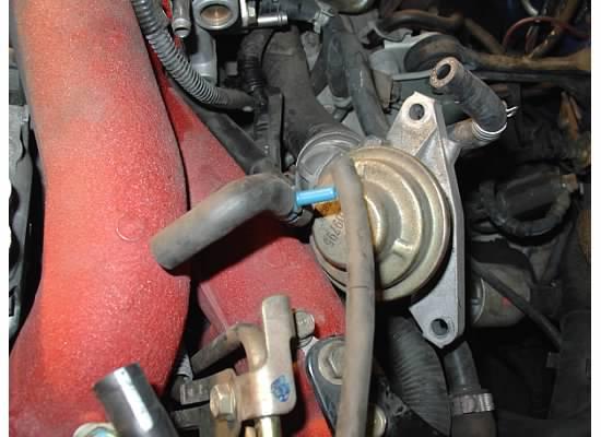
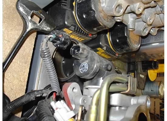
Step 19 – Disconnect turbo inlet hoses One of these hoses is connected to the purge valve (UFO looking thing behind the power steering pump). The other is routed aft of the engine and onto the boost control solenoid on the passenger side strut tower. In the picture below, only the boost control solenoid hose is disconnected.
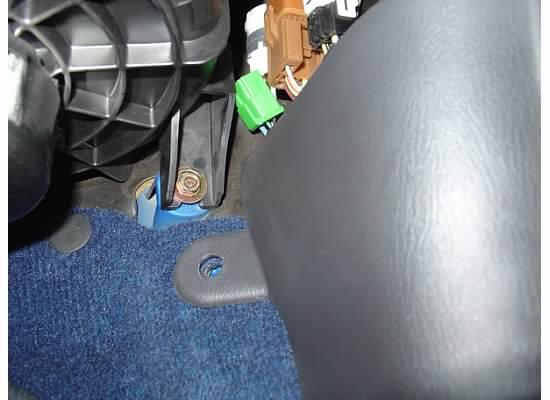
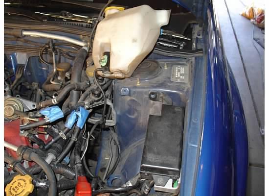
Step 20 – Remove windshield washer fluid tank – Located on the driver side near the fuse box. First, remove the two 10mm bolts holding the tank to the strut tower, then lift the tank up, but not too far, since you will need to disconnect the green connector going to the pump. If you’re low on fluid, I would disconnect the tube going to the pump and put the tank on the bench. If you are decently full, you can just lay it on the cowl like I did.
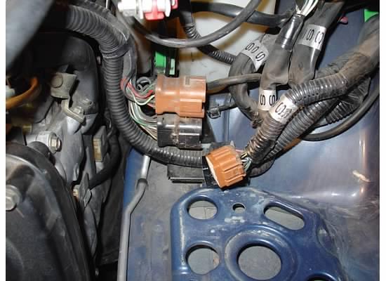
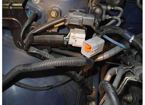
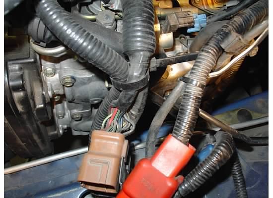
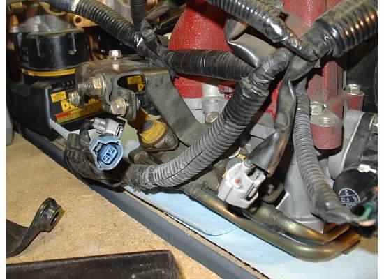
Step 21 – Disconnect engine harnesses – There are four of them: two on each side of the engine bay. On the driver side, they are the square brown and black harnesses right behind the battery. On the passenger side, there is a light gray and dark gray connector on the strut tower near the boost control solenoid. In the second picture below, I only disconnected one of them. Do both.
Step 22 – Remove the driver side engine harness bracket – The driver side harnesses that you just removed is attached to a black bracket. First, take a pair of needle nose pliers and dislodge the wiring harness that is at the bottom so you can gain access to the bolt holding the bracket to the chassis. Then, using a 10mm socket and extension, remove the bolt and bracket and put on the bench.
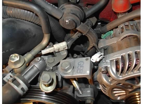
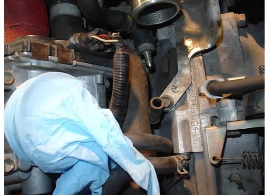
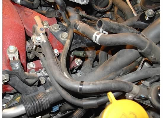
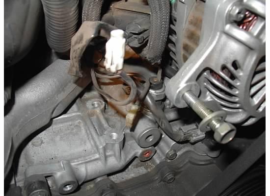
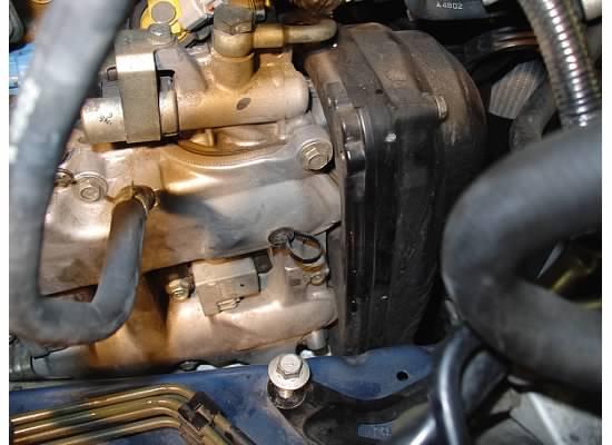
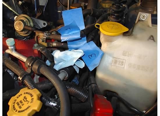
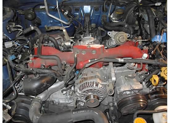
Step 23 – Disconnect engine sensors – There are three sensors that you will need to disconnect: oil pressure sensor, crank position sensor, and coolant temp sensor. These all are located below the alternator. The coolant sensor is on the crossover pipe, directly below the intake manifold. This is probably the most difficult to get to, and cannot be seen in the picture below, but can in the second picture.
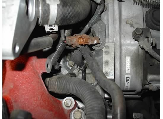
Step 24 – Disconnect knock sensor – This is on the back of the engine near the throttle body. The connectors are brown, so they should be easy to spot.
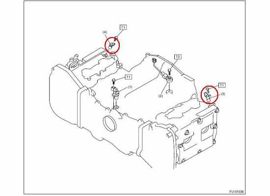
Step 25 – Disconnect camshaft position sensors – There are two of them, one for each bank of cylinders. They have a light gray connector going to them and are located on the aft side of the cylinder heads, near the TGV motors. They are fairly hard to get to, so pictures are even worse, so I don’t have any. I do have the diagram below to give you a good reference.
Step 26 – Disconnect coil packs – The coil pack wiring harnesses are black and white. Disconnect all four of them. When reconnecting, always remember that blacks are always in the back.
Step 27 – Disconnect coil pack valve cover ties – There are two “zip ties” that route the coil pack wires down to the coil packs located on the valve covers. On the passenger side, it is towards the front and on the driver side, it is towards the rear. I took two small flat blade screwdrivers and pried the locking tong up while pushing the zip tie out with the other.
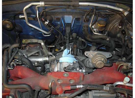
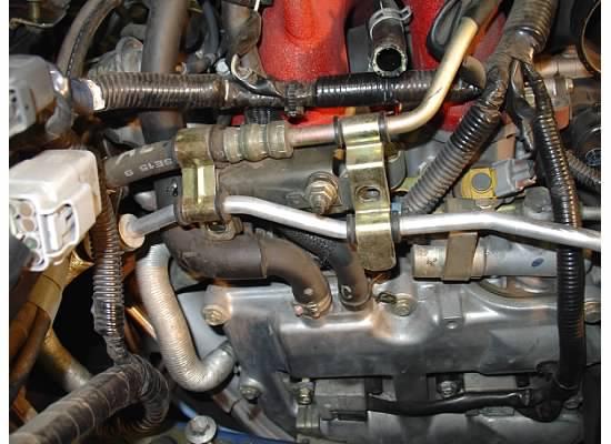
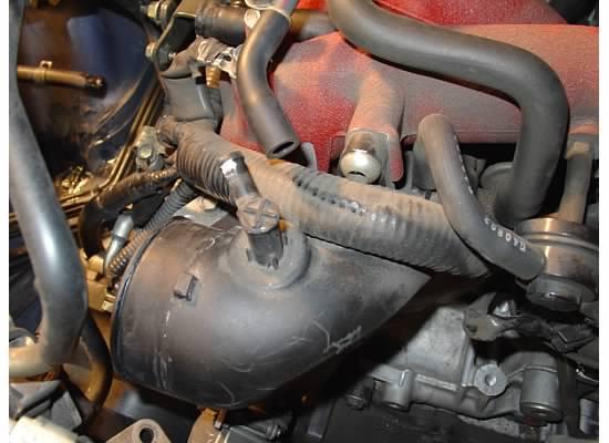
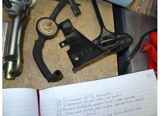
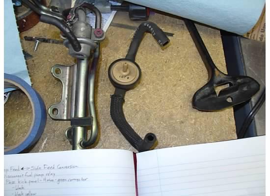
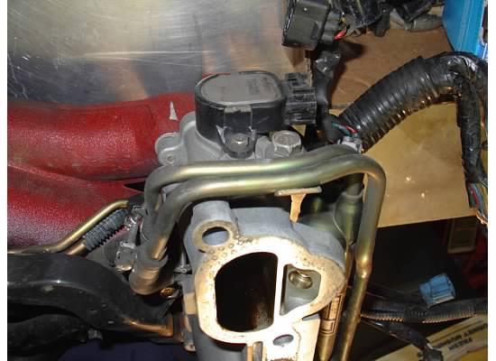
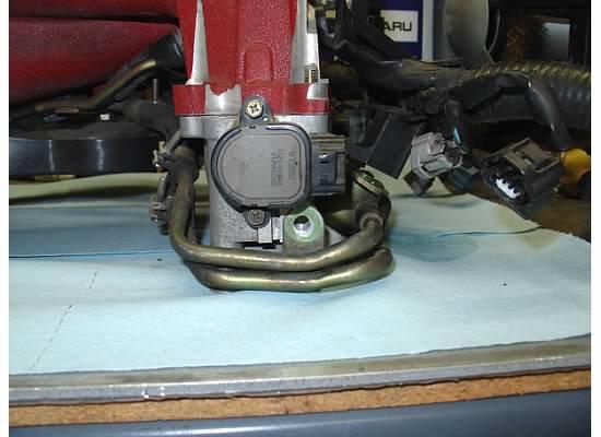
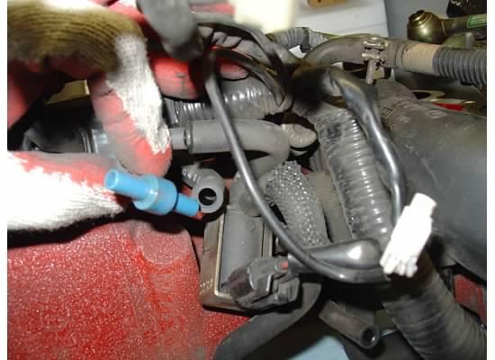
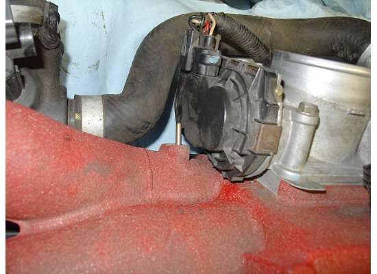
Step 28 – Remove purge valve assembly – This is the UFO looking assembly behind the power steering pump. You already disconnected the hose going to the turbo inlet, now disconnect the other piece from the blue tee and the intake manifold. The result should be this:
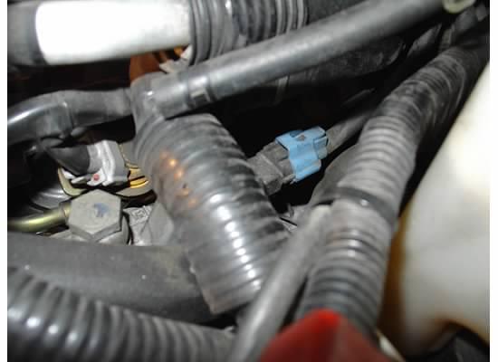
Step 29 – Disconnect AVCS solenoids – There are two of these, one on each cylinder head. They are blue and easy to get to. Disconnect them.
Step 30 – Release engine harness zip tie – Using the two screwdriver method again, remove this zip tie. If you don’t want to reuse, just snip it off.
1-30-2012
Step 31 – Disconnect turbo inlet – The turbo inlet will come out with the intake manifold, so this is the last connection to its engine brethren. Use a 8mm nut driver to loosen the clamp at the turbo. Then, use a 6mm Allen wrench and remove the bolt that holds the turbo inlet to the front of the intake manifold. Wiggle the inlet a few times to make sure everything is loose. I don’t have a picture of this step.
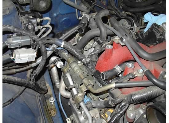
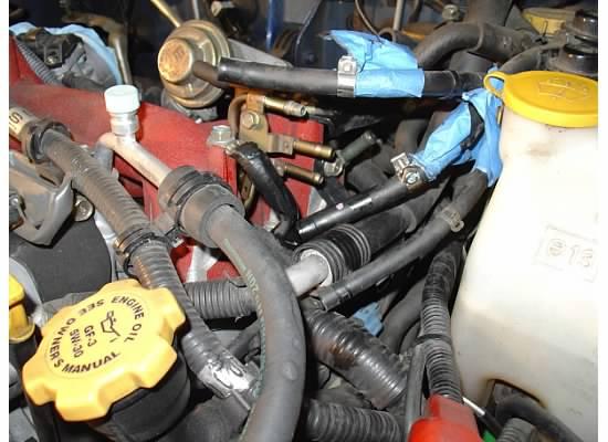
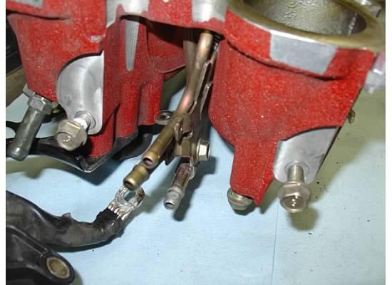
Step 32 – Remove fuel lines – I labeled mine before I removed them. In case you forget, the top one is supply, the middle one is return, and the bottom one if for the purge valve. A #2 Philips screwdriver and needle nose pliers gets the clamps off. Some fuel will spill, so put a paper towel underneath.
Step 33 – Disconnect driver side engine harness cover from intake manifold – The engine harness is shielded by a rigid plastic cover on the driver side just above the injectors. Three 12mm bolts hold the cover to the intake manifold and the TGV housing. Remove all three, this will help with clearance issues around the A/C hose.
Step 34 – Remove coolant L-hose – This is the hose that we disconnected earlier from the bottom of the coolant tank. Take a pair of needle nose pliers and remove the clamp, then remove the hose.
Step 35 – Disconnect boost gauge from bypass valve – If you have a boost gauge, the reference line is attached to the fuel supply line and tees into the bypass valve hose. I disconnected the boost hose and moved the zip tie.
Step 36 – Remove passenger side valve cover breather tube – There are two breather tubes coming from the passenger side valve cover. Removing the one in the front will help with getting the manifold off. You’re almost there!!!

Step 37 – Remove A/C belt – You will need to move around the A/C system, so the first part is to remove the belt. Similar to the other belt, loosen the set bolt, then loosen the tensioner bolt until you can get the belt off. Mine were in bad shape, so I got a new one.
Step 38 – Remove A/C compressor – The compressor is held on by four 14mm bolts. I would recommend you first remove the black bracket that is on the driver side of the compressor using a 14mm socket. Two bolts on the top hold the bracket to the compressor, and one that attaches it to the engine block. Once removed, there are two more 14mm bolts on the underside of the compressor. Once all of the bolts are out, you can move the compressor.
Step 39 – Disconnect A/C hose from firewall – From the compressor, a return hose goes towards the firewall and attaches to a grommet with a 10mm nut. When you remove the nut, you can shift the whole A/C system forward, which helps get the intake manifold out.
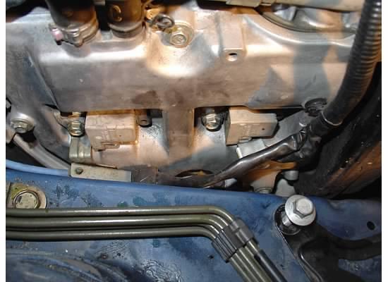
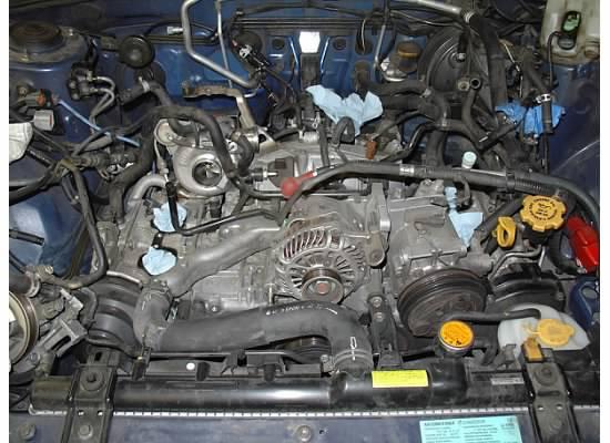
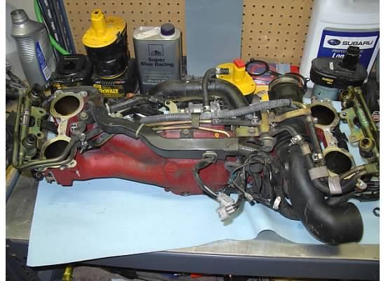
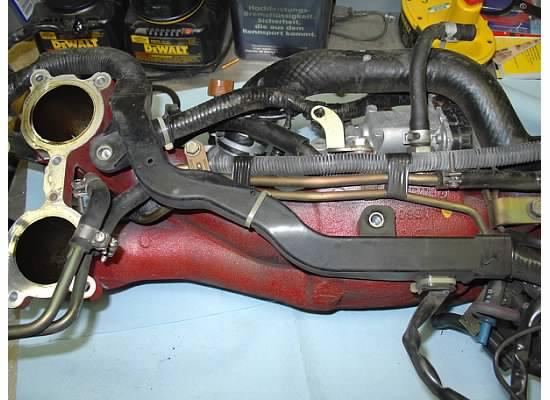
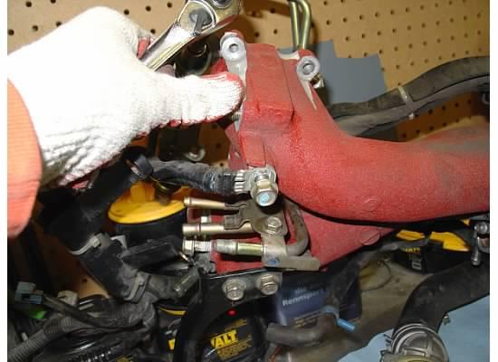
Step 40 – Remove intake manifold bolts – You’re there! On each side, there are four 12mm bolts that hold the intake manifold to the cylinder head. Remove the bolts and leave the rest there. The picture below shows which ones to remove. Basically, remove the bolts that go through the TGV housing only. The others just attach the TGV to the intake manifold, so again, leave these attached.

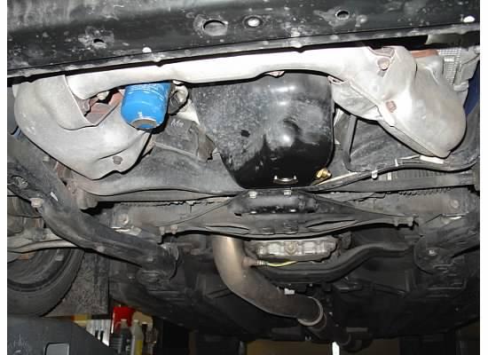
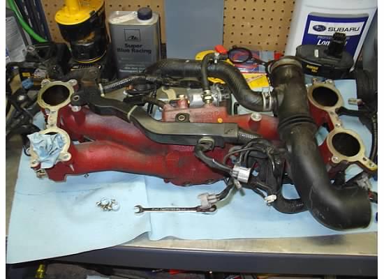
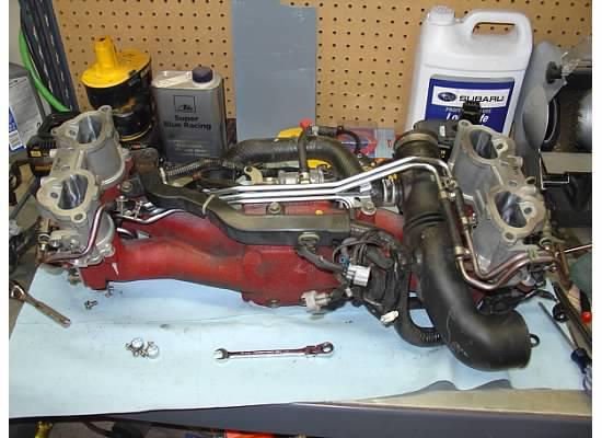
Step 41 – Remove the intake manifold – It should be loose by now. I found it best to grab a buddy and try to raise the manifold out in unison. The guy on the passenger side should pull the turbo inlet forward while making sure the PCV tube doesn’t get caught on anything. The guy on the driver side should keep the A/C compressor leaned forward. Make sure the wiring harness doesn’t get snagged! Also, the TGV motor will hit a hard coolant line in the rear, so keeping the A/C compressor forward will give you more room for clearance. Once its out, grab a beer! I recommend a Colorado micro brew (Left Hand works). I strongly recommend you do the TGV and fuel line swap on a bench. Cover the exposed cylinder heads with a paper towel so nothing gets in them.
Step 42 – Disconnect TGV sensors/motors – Both the sensors and motors need to be disconnected.
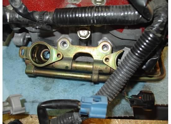
Step 43 – Remove fuel injectors – Using a Torx T-25 bit, first remove the injector hold-down plate, then using a few flat blade screwdrivers, the injectors should pop out. BE SLOW! DO NOT USE PLIERS TO PULL THEM OUT!!! The top cap can crack or break off, and Deatschwerks will not give you a refund for an injector with a broken injector top.
Step 44 – Remove power steering line bracket – Two 12mm bolts hold the olive drab bracket to the intake manifold. Remove both of these and take the bracket off.
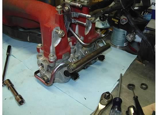
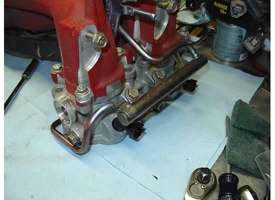
Step 45 – Remove fuel rail bolts – On each side, two 12mm bolts hold the fuel rail to the TGV housing. There is one 12mm bolt on the side of the TGV that also holds the fuel rail. Remove all six of the bolts.
Step 46 – Remove the TGVs – Each TGV are attached to the intake manifold via six 10mm bolts. Based on which TGVs you are installing, you might need a few 10mm nuts, since my WRX TGVs had two studs installed in each TGV. The 05 STI TGVs have two nuts on the driver side, but none on the passenger side, so I needed to source two nuts.
Step 47 – Loosen engine harness – The engine harness is attached to the bottom of the intake manifold by two 10mm bolts. You will need to remove these bolts to gain access to the fuel rails. Also remove the ground straps that are on top of each side of the intake manifold.
Step 48 – Remove purge valve tee – I’m not sure why I did this, maybe for access or something. But its your call.
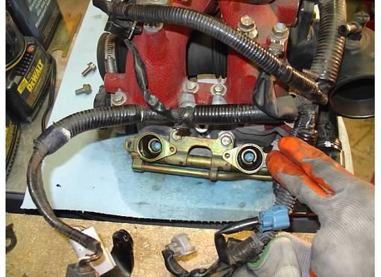
Step 49 – Disconnect the fuel pressure regulator – Next to the throttle body, the fuel pressure regulator is connected to the intake manifold to get its vacuum/boost signal. Remove the entire hose. You will need to get a longer piece for the top feed fuel pressure regulator.
Step 50 – Disconnect the supply fuel line – Two 10mm bolts hold the fuel supply line to the intake manifold and other hard fuel lines. Remove these bolts to enable the removal of the fuel lines. Then, loosen one of the rubber fuel hoses and remove the hard line.
Step 51 – Remove fuel lines – The other hard lines are attached to the intake manifold by one 10mm bolt and one 12mm bolt. Remove both, and fish the lines from underneath the engine harness.
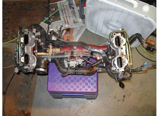
ASSEMBLY – So your done disassembling. Awesome! I wish I could say “installation is the reverse of removal”, but this isn’t the case. Some minor fabrication is needed to put the top feed parts back on your manifold. Also, all my torque specs are in ft-lbs. If you do not have a torque wrench that goes down to 3.6 ft-lbs, purchase one that is in in-lbs, and simply take my specs and multiply by 12.
Step 52 – Enlarge passenger side fuel rail bolt – First, before installing the top feed fuel rail, you will need to enlarge the 12mm bolt hole in the fuel line bracket. I used a step drill and ensured that it enabled the 12mm bolt to pass through. No picture, sorry.
Step 53 – Attach fuel lines to manifold – First, remove the supply line from the rest of the lines. Fish the top feed lines underneath the engine harness and attach the lines with the 10mm and 12mm bolts. Torque spec for the 12mm is 13.7 ft-lbs, 10mm is 4.7 ft-lbs.
Step 54 – Reattach engine harness – Reattach the engine harness to the intake manifold. Torque the two bolts to 13.7 ft-lbs. See above picture.
Step 55 – Attach TGVs – Using the new gaskets, attach the TGV housings to the intake manifold. The driver and passenger side are not identical, so match the new TGVs to your old TGVs. I loosely tightened four of the six bolts/nuts, then flipped the manifold up, installed the inner two bolts, then torqued them down. Spec is 6.1 ft-lbs.
Step 56 – Attach fuel supply line – Reconnect the fuel supply line, then attach with two 10mm bolts to the other hard lines and the intake manifold. Torque spec is 3.6 ft-lbs.

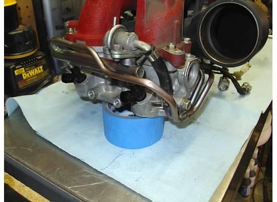
Step 57 – Install injectors – Apply a light coat of synthetic grease to the injector o-rings, then insert them into the TGV housing. Center the fuel rails over them and push down. You should feel the o-rings seat into the TGVs and rails. NOTE: If you are using Injector Dynamics injectors, take a Nintendo DS stylus and push on the pintle. Then, blow compressed air through the pintle to ensure the pintle is not stuck closed. This happened to me and took me 3 days to diagnose, along with several hours of disassembly to get to the injectors again.
Step 58 – Tighten fuel rails – Install the three 12mm bolts per side to tighten the fuel rails to the TGVs. Two are in between the injectors, the third is on the side of the TGV. Torque spec is 13.7 ft-lbs.
Step 59 – Attach passenger side grounding straps – Reinstall the grounding wires to the intake manifold. Torque to 13.7 ft-lbs.
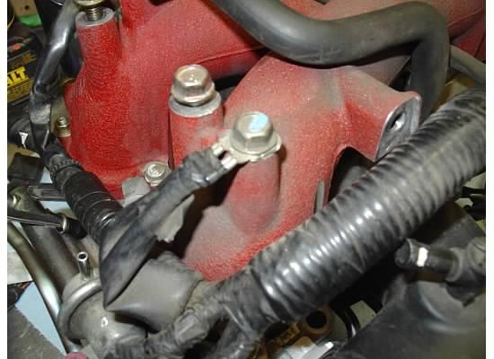
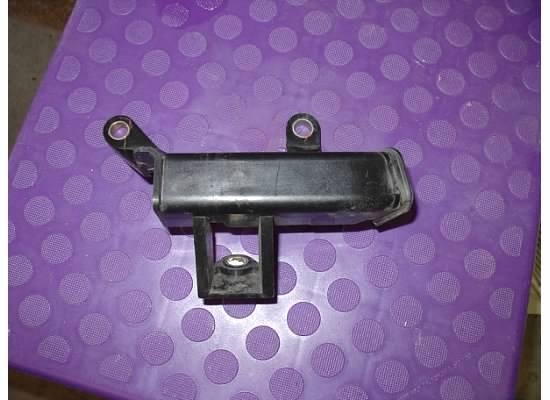
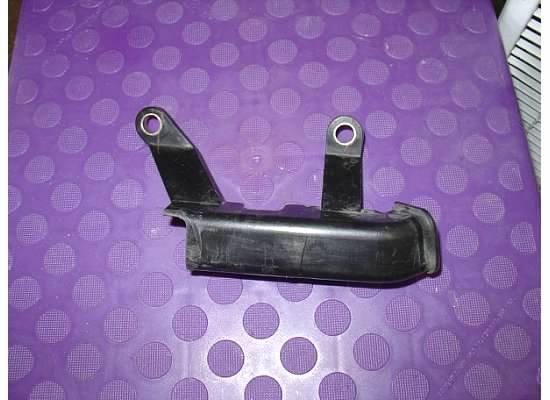
Step 60 – Trim engine harness cover – Ok, now some fab work begins. On the driver side, you have a harness cover that attaches to the intake manifold. On your old TGV housings, they had a bolt hole for the third bolt. On the top feed TGVs, there is no hole, so you will need to trim the third leg off the cover. Snip off the two zip ties and use a cutoff saw to trim the leg off. Once trimmed, re-zip tie to the harness and install onto the manifold. Torque spec is 13.7 ft-lbs. See pictures below:
Step 61 – Attach driver side grounding straps – Now that you have the cover back on, you can attach the grounding wires to the intake manifold. See picture above. Torque spec is 13.7 ft-lbs.
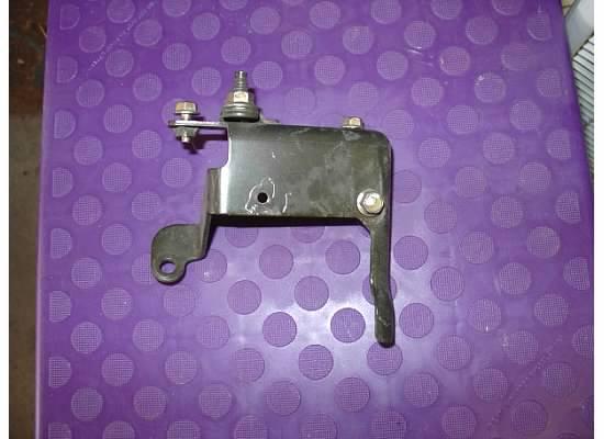
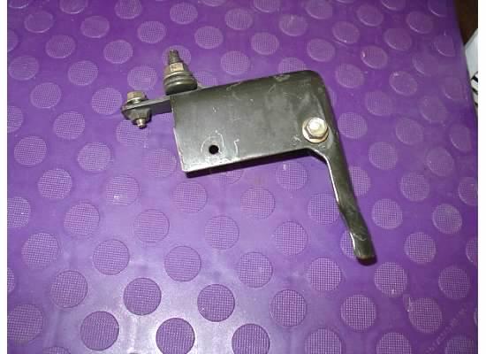
Step 62 – Trim power steering line bracket – Hope you still have that cutoff wheel handy, cause you're going to need it again. Due to the same reason for trimming the harness cover, you will also need to trim the bottom support of the power steering line bracket. See pictures below. Torque spec is 13.7 ft-lbs.
Step 63 – Route fuel pressure regulator vacuum/boost hose – The old fuel pressure regulator was located near the center of the manifold and had a short little 180 degree loop to connect to the manifold next to the throttle body. On the top feed rails, the regulator is near injector #1, so you will need to get some similar sized hose and connect the regulator reference to the nipple near the throttle body. This is very important, so I would zip tie these connections to ensure the hose won’t pop off.
Step 64 – Connect injectors – Like I mentioned, I used the Injector Dynamics Plug-n-Play conversion pigtails, so this took 10 seconds. If you don’t go this route, you will need to cut off your old connectors and solder in some top feed ones. Whatever you do, at the end, you need to have your injectors connected. Also, polarity doesn’t matter when repining.
Step 65 – Install the manifold – Get your buddy again. Scrape off any of the old gasket remaining on the cylinder heads. Install the new gaskets, vacuum out the intake tracks, and lower the manifold onto the heads. Be sure the turbo inlet gets onto the turbo inlet. I partially tore mine, so be careful. Also look for the injectors hitting the AVCS solenoids. I had to rotate mine to clear them. This should be easier than removal if you deleted the TGVs, since you don’t have sensors or motors to get in the way. If you didn’t, why not? You really want to do this again to delete them? Anyways, to each their own. Torque spec is 18.1 ft-lbs.
Step 66 – Install A/C compressor – Install the two lower bolts that hold the compressor with 21.3 ft-lbs. Wait to install the other two next step.
Step 67 – Install A/C bracket – Tighten the bracket to the block with 26 ft-lbs. Then install the other two compressor bolts. Tighten to 21.3 ft-lbs.
Step 68 – Attach A/C hose to firewall – I couldn’t find a torque spec, just get it decently tight.
Step 69 – Install A/C V-belt – First, get the belt on and centered. Then tighten down the tensioner bolt until ~9-1

Great detail and pics!
Posted by Diggymart on 11/1/19 @ 11:04:21 AM