You must be logged in to rate content!
40 minute read
Fuel System Upgrade/Install
Compliments of 94Canuck @ www.supraforums.com
As part of my current build I was going through the process of upgrading my fuel system. I thought I would detail each step (mostly anyway) as to how I went about it. I've made every effort to be as detailed as possible, and provide pictures where applicable.
Some disclaimers before we get started:
1.) This is the first fuel system I've done, and so there may be other ways, better way, or more efficient ways of doing a fuel system.
2.) I am not a trained mechanic but have experience with this car, and others. Take your time, and don't do anything stupid like rounding off nuts, or bolt heads. Use appropriate tools or your life could get very difficult.
3.)In a few cases I've added a note for an alternate method. After having things removed there are a few steps that could have been modified that would make it easier for you, I'll detail those.
4.)This is the way I did it, please no flaming about how I'm a douche bag for doing it this way, or whatever. This is meant to help those who don't know what they are doing, and are looking for some help.
5.)I made an effort to point at the part/place referenced. Any confusion should be able to be clarified with the TSRM.
6.)Read through this a couple times before you start.
This guide will be split into the following sections for easy reference.
1.)Shopping List
2.)Intake/Fuel Removal
3.)Fuel Pump Modification
4.)Wiring
5.)System Install
Things which are not covered is the re-install of the Intake side. It seemed redundant as you put things back together in reverse order.
Shopping List
There are two options as I see it when it comes to buying your fuel system.
Option #1 is to buy a pre-assembled fuel kit from the vendor. It has it's benefits such as pre-assembled lines, exact fittings, sometimes extras like fuel pump wrap, maybe a FPR bracket, in nearly all cases the second fuel pump you will need. Basically everything you need in one box, less shopping and looking around for deals or pieces. The downside is the cost. Budget to spend around $2200 - $2500 if you buy a vendor kit.
Option #2 is buy everything on your own. The benefit of this route is money savings. I saved about $1300 buying my kit in pieces and feel it has everything required that is in a vendor kit. I don't have some of the fancy things like a FPR bracket and the pump wrap.
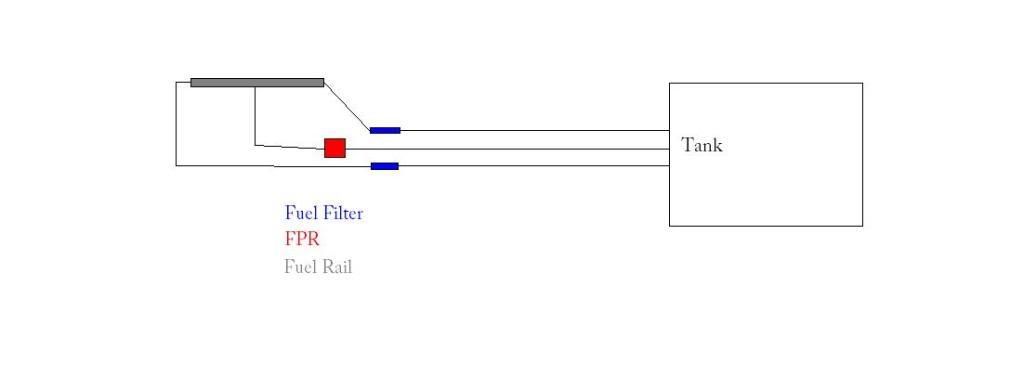
Either way I installed this kit in the same manner as is intended for the vendor kits (most of them anyway). You will run two feed lines from the pump. One will be new, the other will utilize the OEM feed line which is the same size as a -6 AN line. You will run each line to either side of the dual feed rail, and center return to the FPR. This method is tried and true with many MKIV's out there.
If you decide to go with Option #2 here is everything you need to buy, websites to get it, and part numbers where applicable.
Electrical
x2 30/40 Amp Relays
Wire (12 gauge if followed directly. Other options available for different setups)
Wire connectors/ends
x2 25 Amp Fuses
Soldering Gun
Electrical Solder
Wire Wrap
Zip Ties
All of this can be obtained at pretty much any retail store that has electrical stuff.
Plumbing
All required plumbing items can be obtained from Summit Racing. They offer different options for color etc.
20 Feet -6 Stainless Steel Fuel Hose SUM-230620
x3 -6 AN Strait Hose End SUM-220701
x4 -6 AN 90 Degree Hose End SUM-220687
x1 -6 AN 45 Degree Hose End SUM-220686
x2 -6 AN Twist Tite Hose End SUM-220707
x1 -6 AN to 12MM x1.25 EAR-991945ERL
x1 -6 AN 90 Degree Bulkhead Union AER-FBM2082
x1 -6 AN Bulkhead Nut SUM-220639
x1 -6 AN Fuel Filter EAR-230206ERL
Optional New OEM Fuel Filter 23300-49195
Also pick up the following locally:
x3 O-Rings for the FPR
x2 Washer for the Bulkhead Fitting. Washer contains an inner rubber ring made to withstand fuel contact.
Silicone to help sealing the Pump Hanger. Note: Ensure it is resistant to gasoline!
1 foot Injected Fuel Line Hose
Note: I would recommend getting a couple different fittings to test out routing and fitment for your taste. I would suggest a 180 degree fitting, an extra 45 degree fitting, and an extra 90 degree fitting.
Pumps
Most often people run either OEM Denso pumps or Walbro's. Each have their own benefits and draw backs. Search the countless forum threads on this to determine which you are going to go with. Either way you will need two (or 3 depending on your goals) of either kind. I went with Denso's for their reliability history over the Walbro's. They are more expensive than Walbro's new, but both are pretty comparable if you get a good one used on the boards here.
OEM Fuel Pump & Filter 23221-46110 / 23217-46110
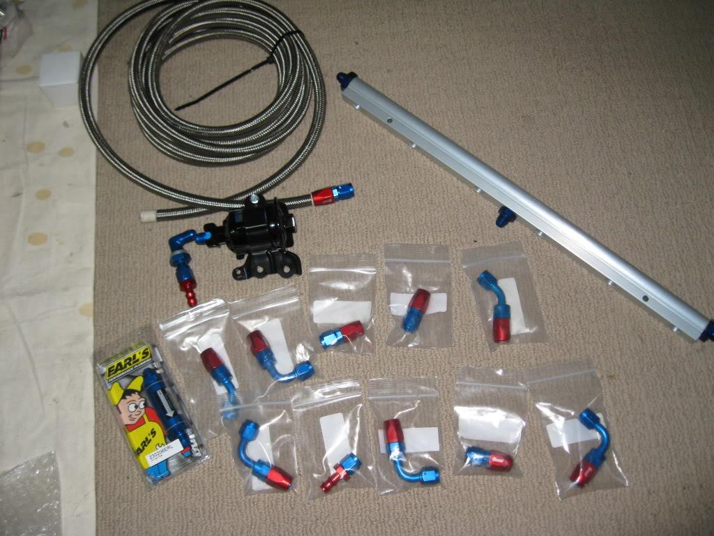
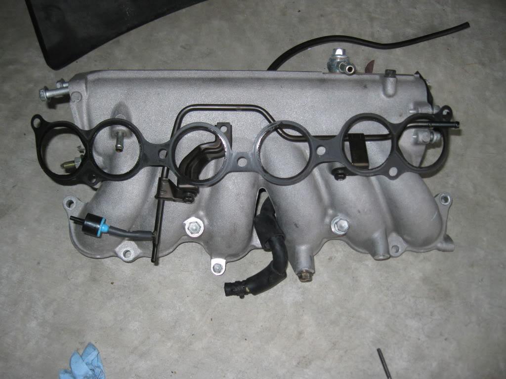
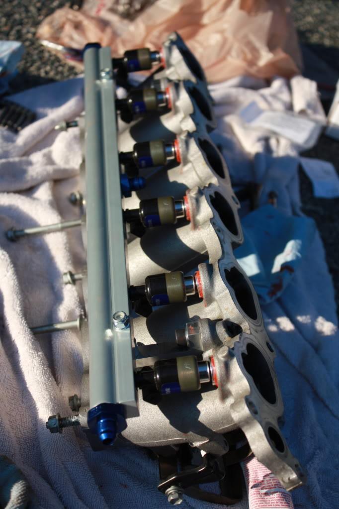
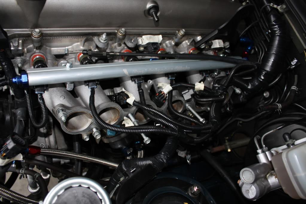
Rail and Injectors
If you are building your own I would HIGHLY recommend Fuel Injection Clinic. Their prices are great, the service is top notch, and their Supra kits come with everything else you need, ie: Rails, Injectors, Injector Bungs, Injector Plugs, FPR.
They have two options really, a -6 Rail and a -8 Rail. In speaking with them at length they educated me on fuel flow, injector sizing and duty cycle, and different methods of running lines. They made me decide on this method. My set up as it stands, with 850cc Injectors, dual -6 feeds, etc will support around 650-700rwhp. The lines and rail themselves, with dual pumps is good to ~1100rwhp so if I ever want more I just swap out injectors.
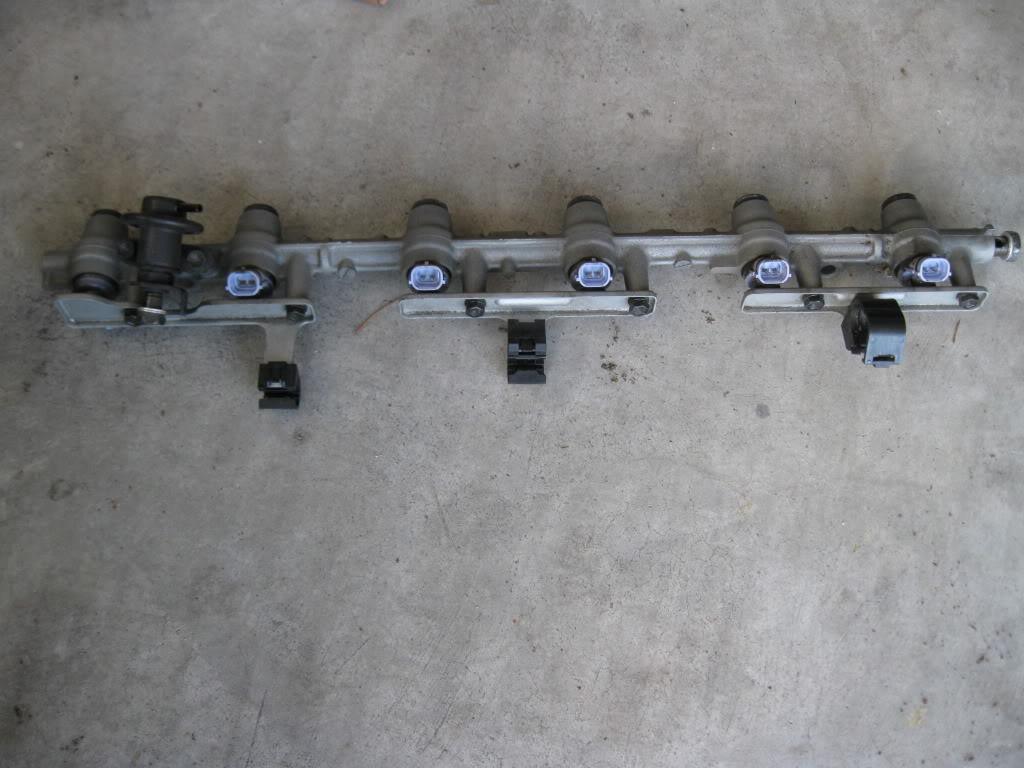
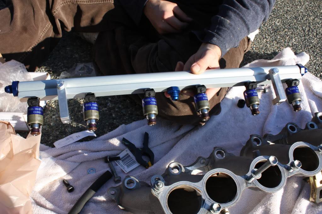
Here is what you will end up with. (Not shown are the injectors, bungs, clips, FPR)
OEM Stuff
This stuff will not be included in a vendor kit, but I would recommend getting each of these gaskets. Why risk using an old gasket with thousands of heat cycles on it when it's all apart and easy to switch out. Either of the OEM vendors here can get these for you. I personally like to deal with Jay Marks and Mike as their prices are a bit lower, however they don't offer the shipping options that Curt at Elmhurst does, but they have higher prices.
Lower Runner to Head Gasket - 17177-46031
Upper Chamber to Lower Runners - 17176-46030
Throttle Body to Upper Chamber - 22271-46030
Even if you are not planning on removing your EGR while you are in there you should probably replace the gaskets for it since it's gotta come off anyway.
EGR Gaskets - 25627-46030 / 25628-46010
With that out of the way you need to ensure you have the proper tools to get the job done. Very basic tools required here.
Sockets (10, 12, 14mm. 10/12 mm Deep Sockets)
Ratchet with 3Â, 6 maybe 9â€Â Extensions
Various Pliers for clips
Utility knife
Zip Ties
Mounting hardware for relays (pick your own, I used double sided tape)
Phillips Screw Driver
TSRM
Shop Towels
Catch containers for various fluids
Intake/Fuel Removal
This job will be split into two basic areas, the engine compartment, and the trunk. Doesn't really matter which end you start at. Probably easier to get everything out of the way first and then put it back together so lets start in the engine bay.
Before you do anything get some masking tape and a marker. Before you remove anything mark where it goes, trust me there is a shit load of stuff in here. Marking it will make re-assembly a breeze. I went with a simple A to A, and Inj #1 format etc.
First do the following:
Disconnect and remove battery
Remove engine under cover
Drain Coolant
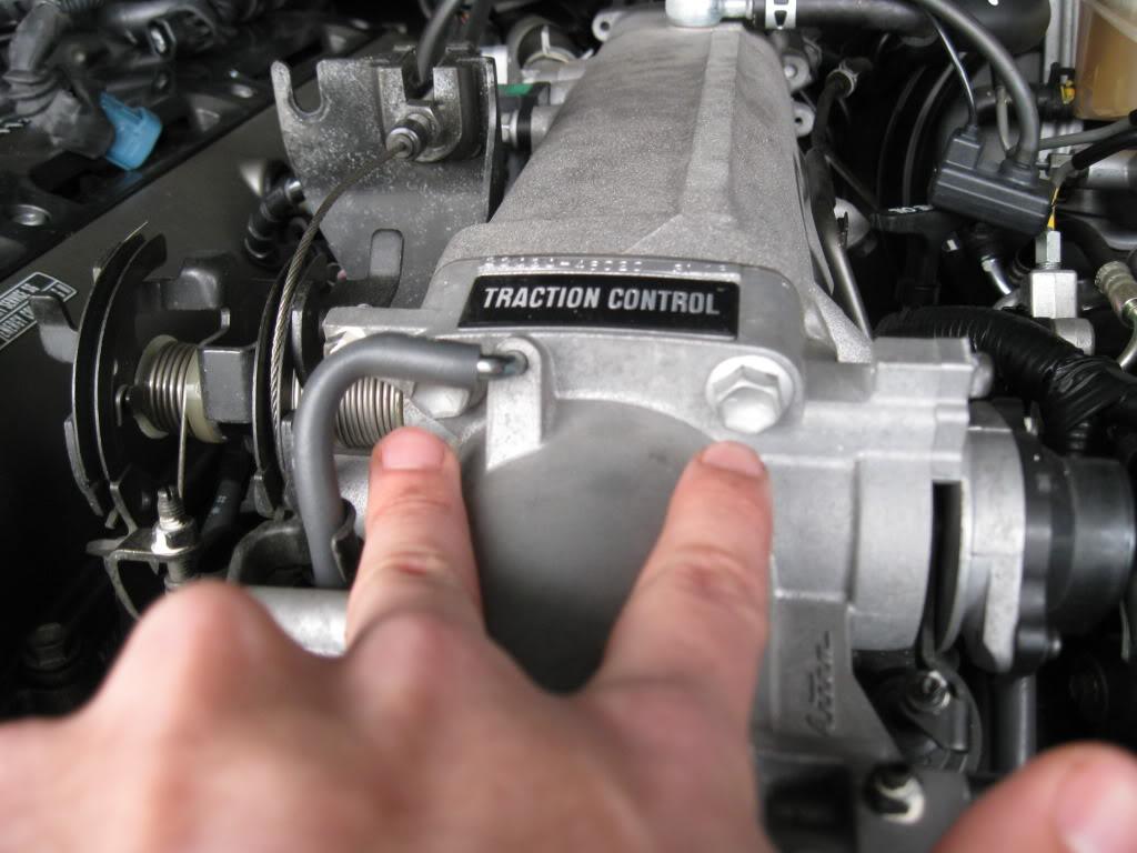
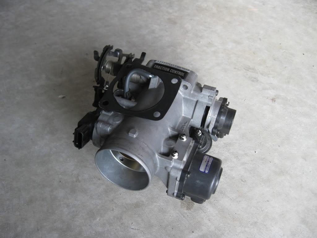
Take a good look at the Throttle Body and find all the hoses and connections that need to be removed before it can be unbolted and taken off. You'll need to get rid of:
Cold side I/C Piping
Accelerator and Cruise Control cables
Throttle position sensor connector
Sub-throttle position sensor connector
Sub-throttle actuator connector
Basically all the electrical connectors.
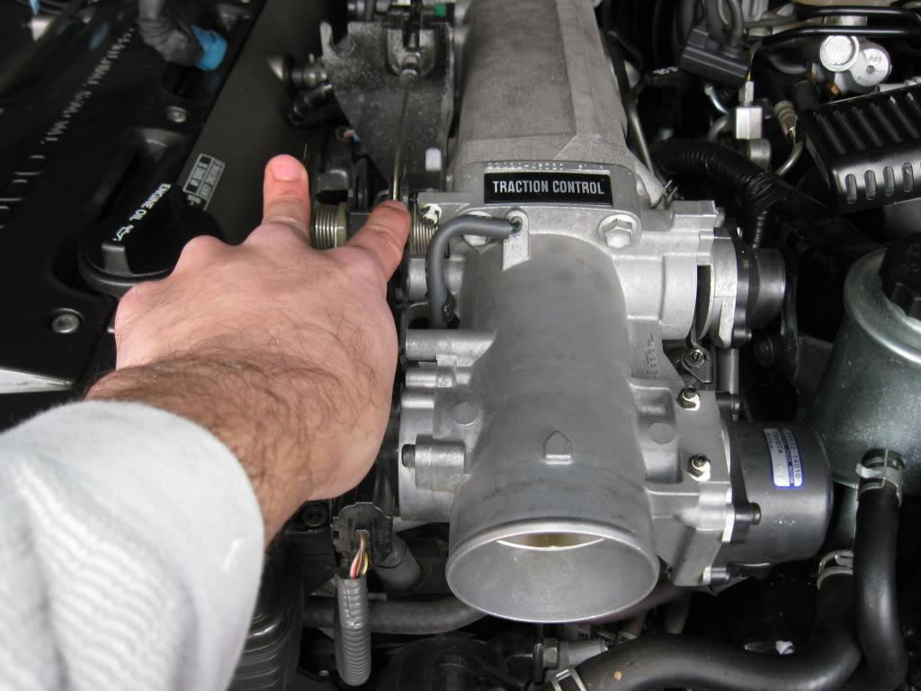
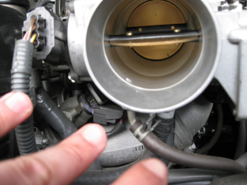
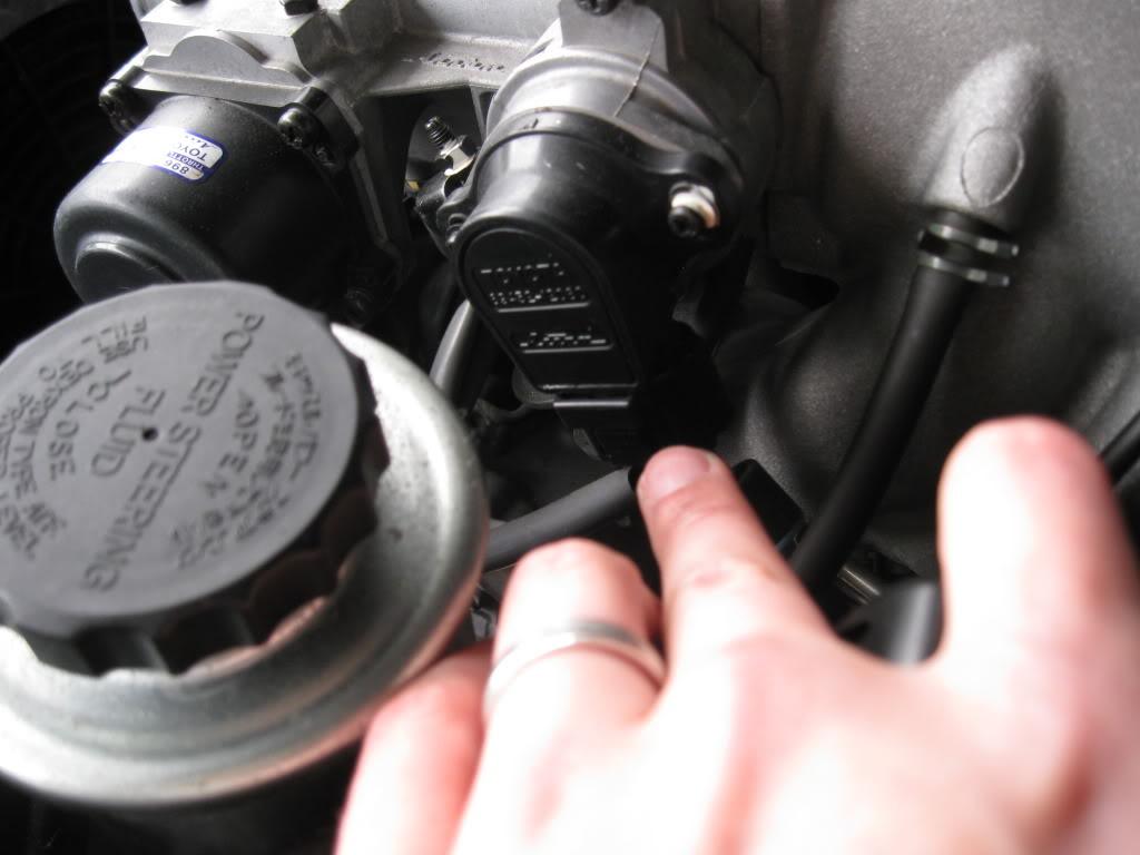
I couldn't get decent shots of the hoses, but there are about four hoses connected here, three on the bottom and one on the side. Two on the bottom are coolant hoses so be aware and catch any excess coming out. The other are vacuum hoses, one is at the very front of the TB, the other is on the back connected to a check valve, it's easy to miss.
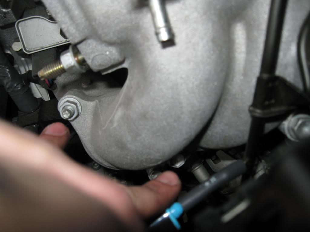
There are two bolts, and 2 nuts holding the TB on. Use a 12mm socket and extension to get to the bottom ones.
It might be easier to get the bottom coolant lines off once the TB is unbolted, they are pretty short lines without a lot of give.
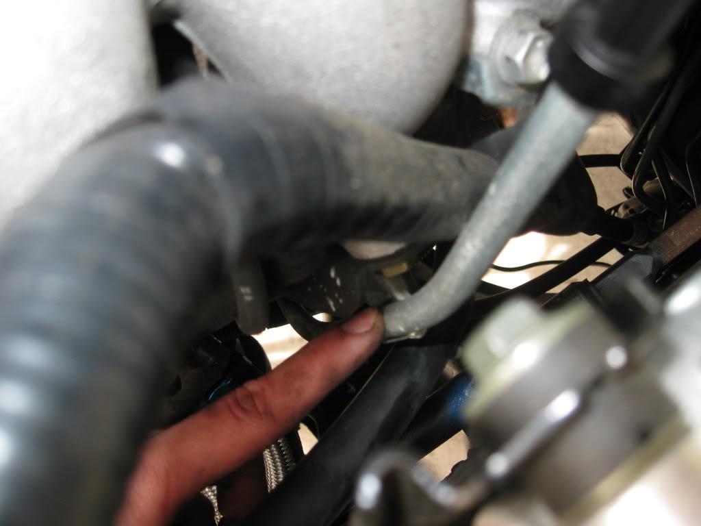
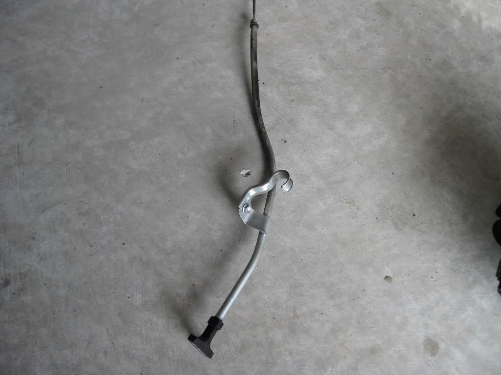
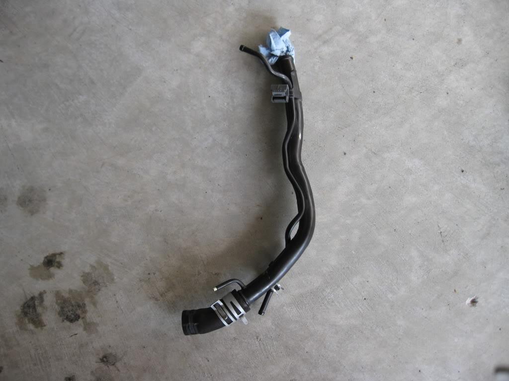
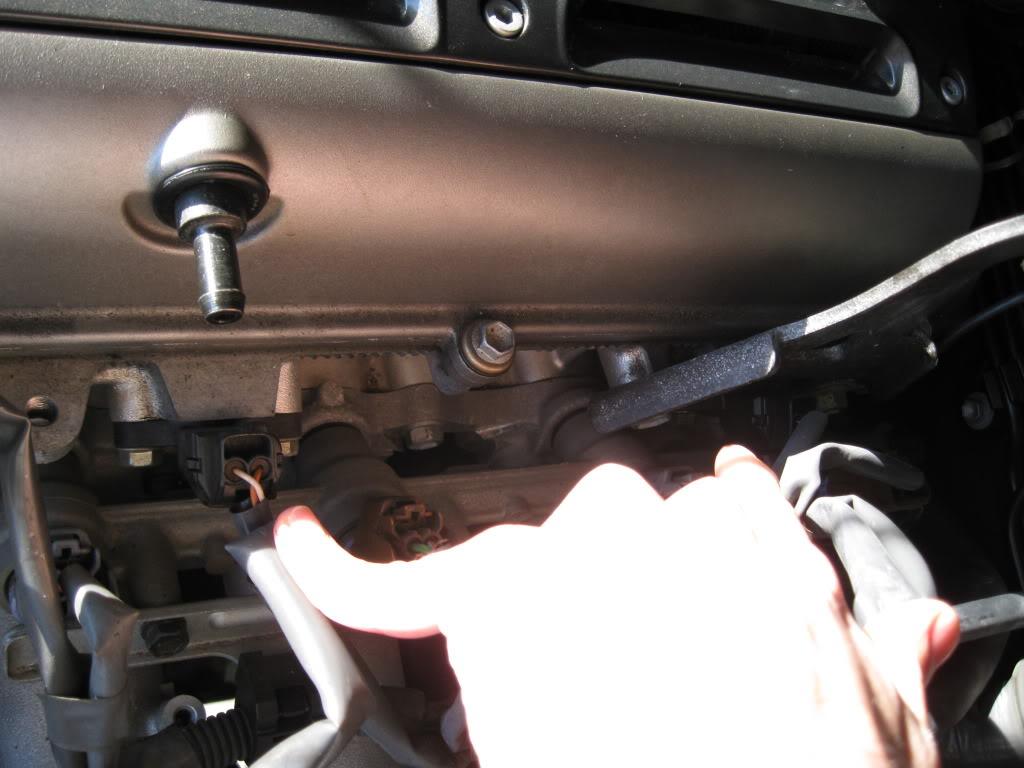
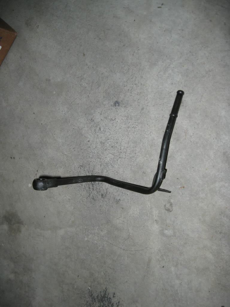
Next take out the oil dip stick guide, as well as unclip the fuel return hose which is on the same piece. Once it's unbolted you need to tug up on the guide, it will pop out of the oil pan at the bottom. Cover the oil pan hole to prevent debris dropping in.

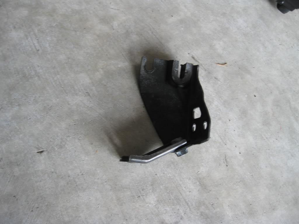
Now remove the air intake chamber stay/cable bracket.

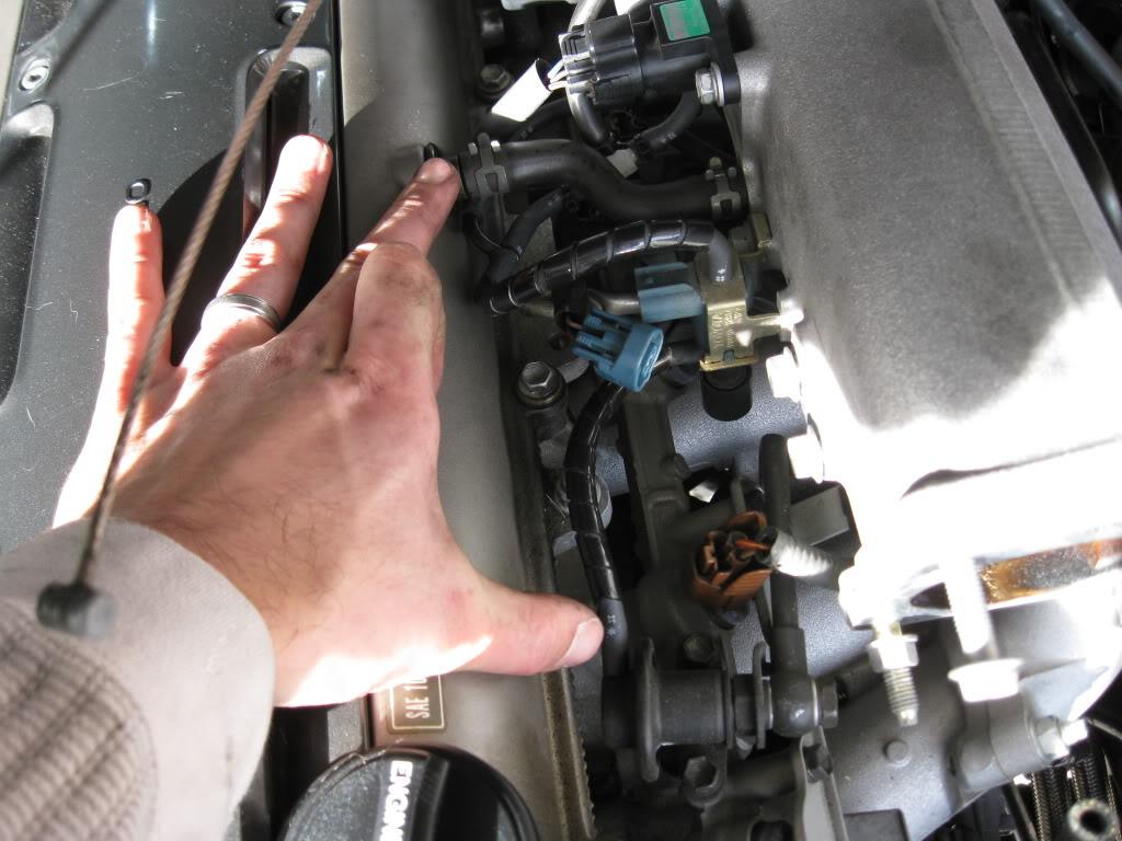
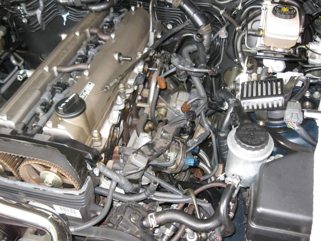
Next start working on removing all electrical connectors and hoses attached to the upper chamber. Disconnect:
IAC Valve connector
TPS Connector
VSV's for FPR and EGR
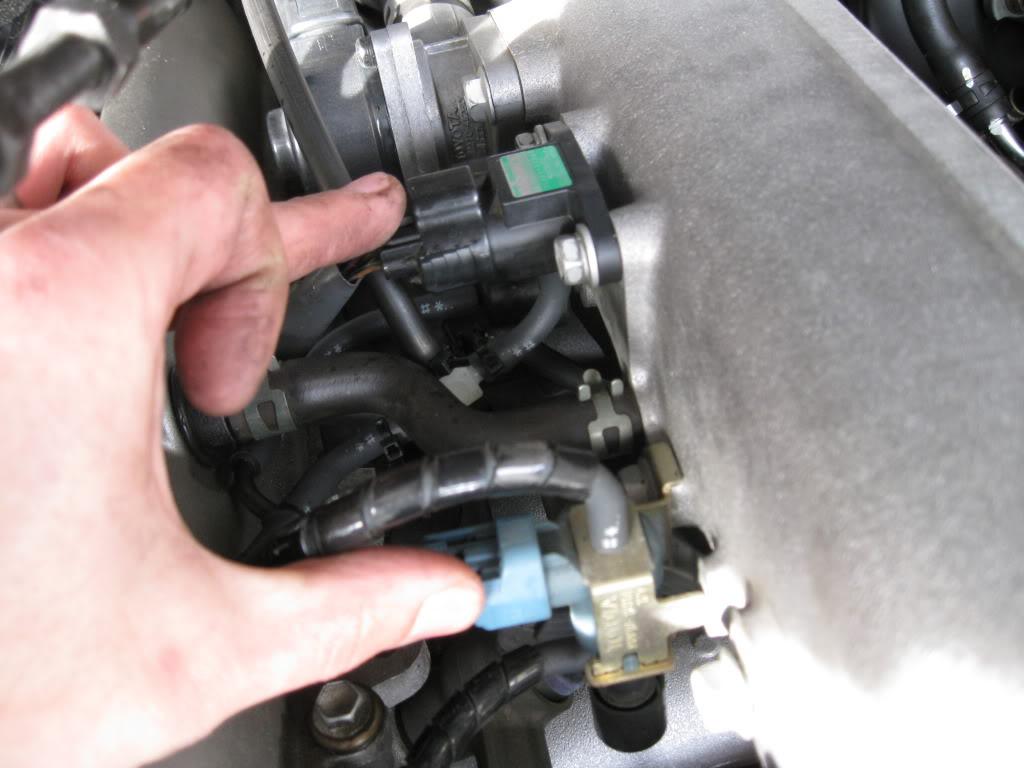
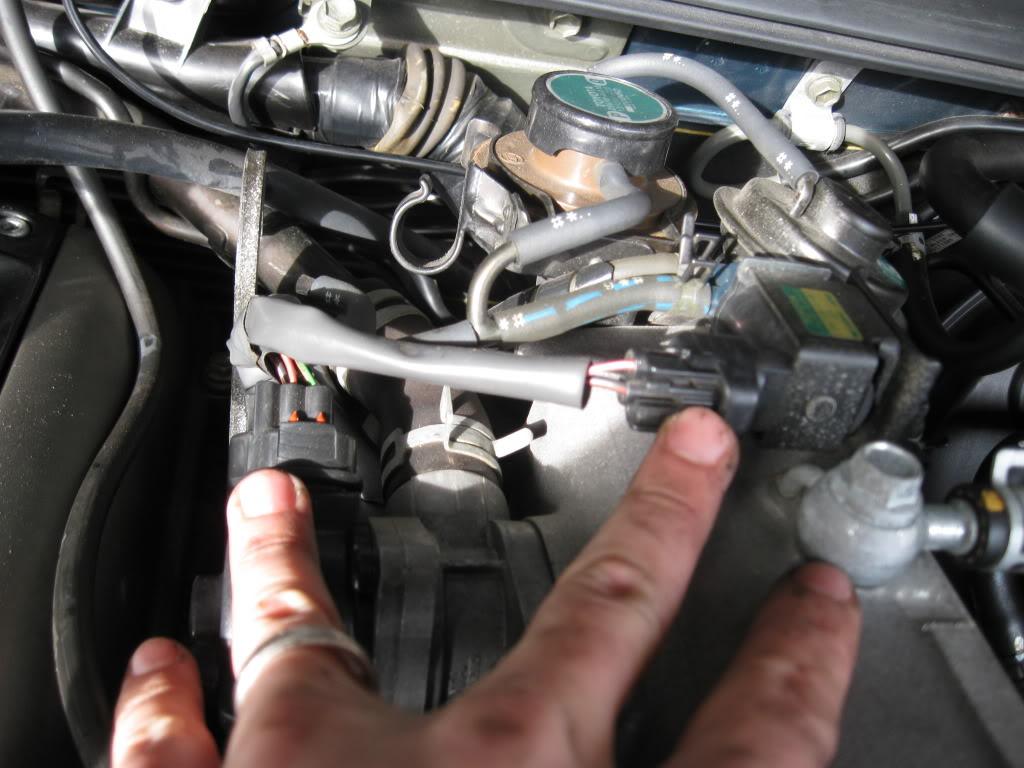
Now the hoses:
Air Hose on IACV
Air Hose on IACV Pipe to Chamber
EGR hose from IACV Pipe
PCV hose from PCV valve cover
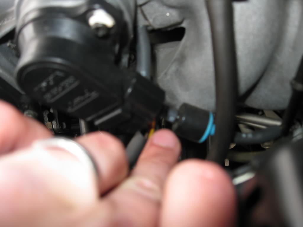
Vacuum hose from FPR.
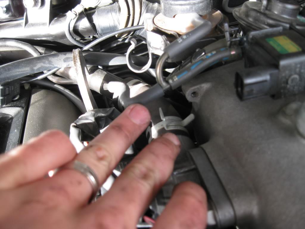
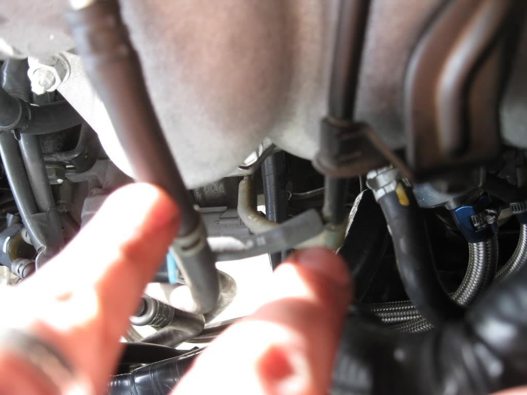
We move to the front side of the chamber now and deal with the coolant/vacuum hoses there. These hoses all relate to the charcoal canister operation. Take a look around and find out where everything routes too. Basically disconnect every hose you can see. Some of these route up through runner 3 and 4, you can disconnect them on this side, or the back side whichever you find easier, it doesn't matter.
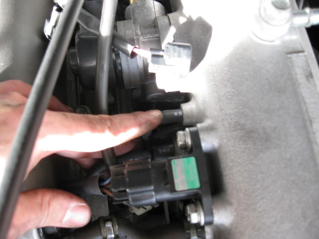
With all this disconnected you deal with removing the EGR. There is already a great write up for this here. Thanks to 93MKIV to making that and Mike (site owner, same person idk??) for hosting it up.
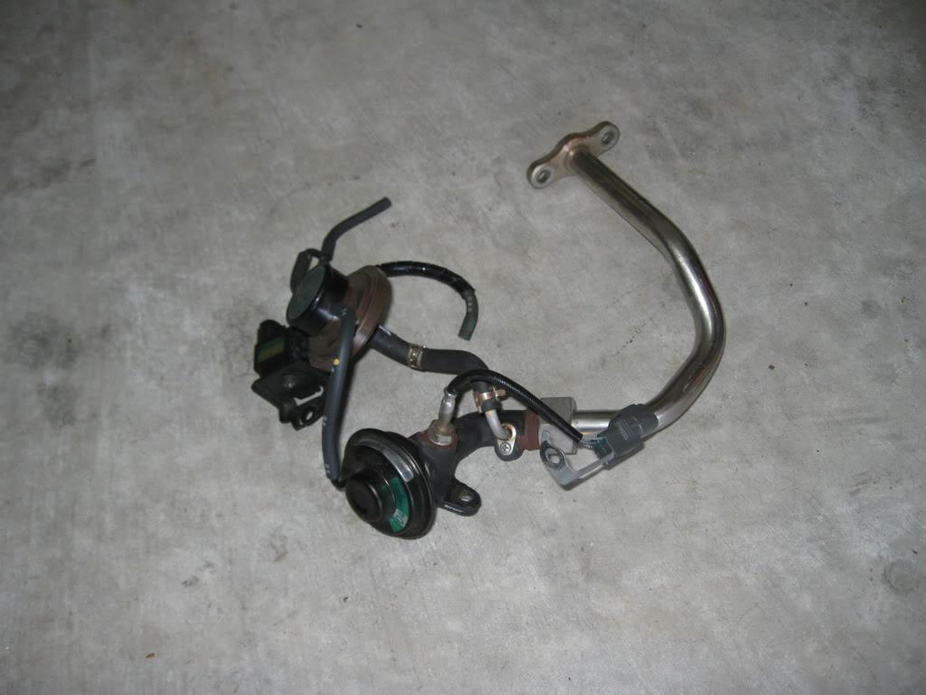
I went the route of complete removal, so remember your block off plates/gaskets. Looks so much cleaner without that mess in there.
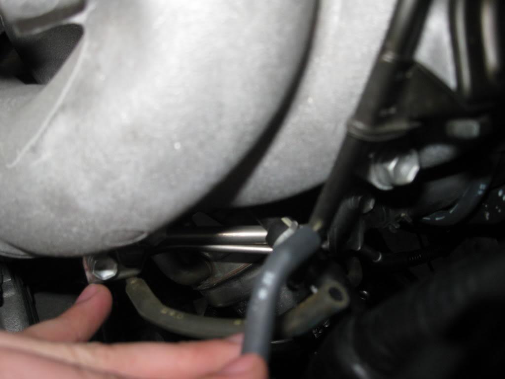
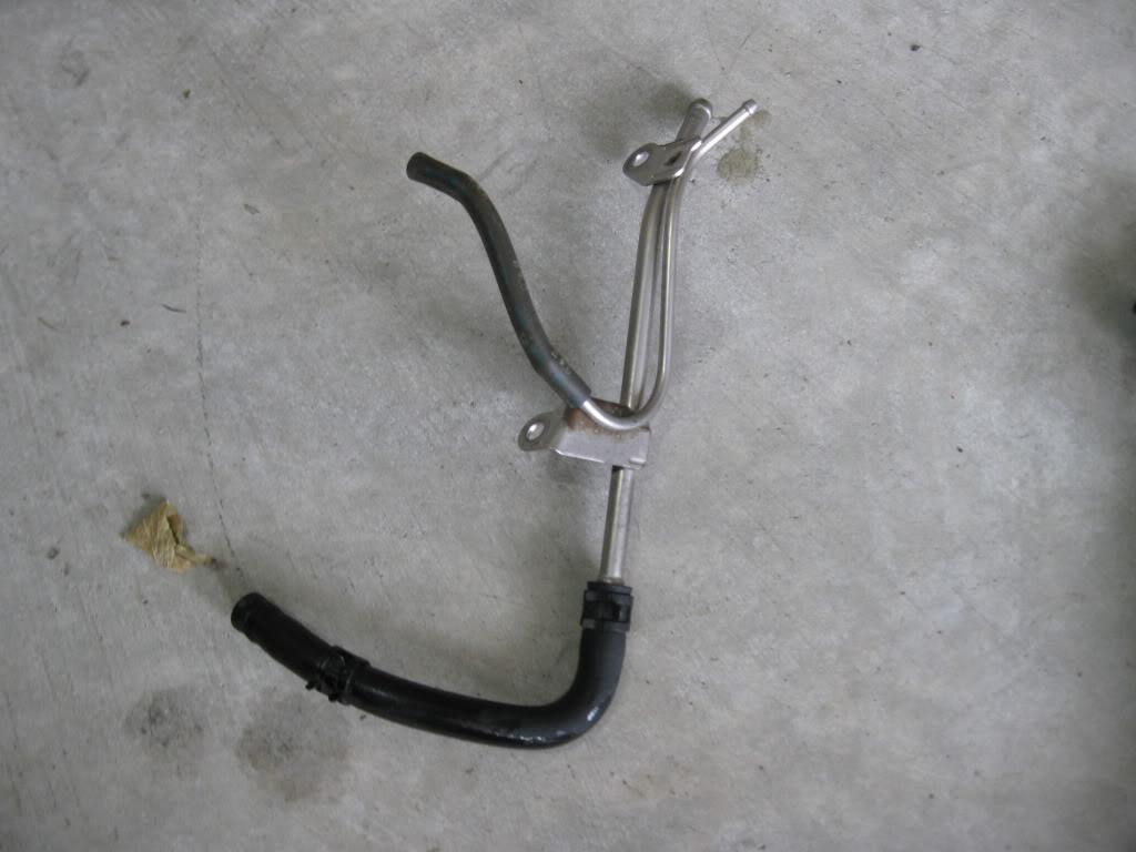
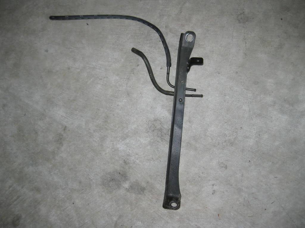
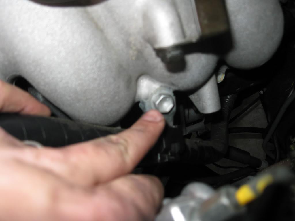
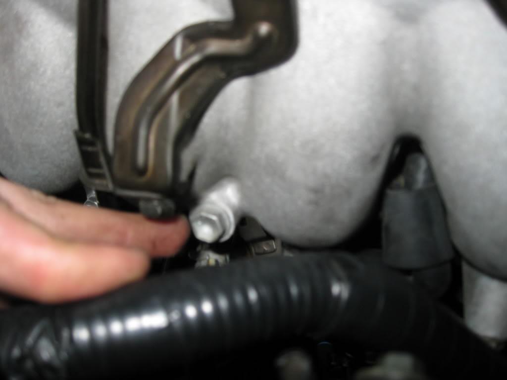
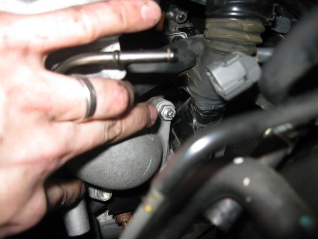
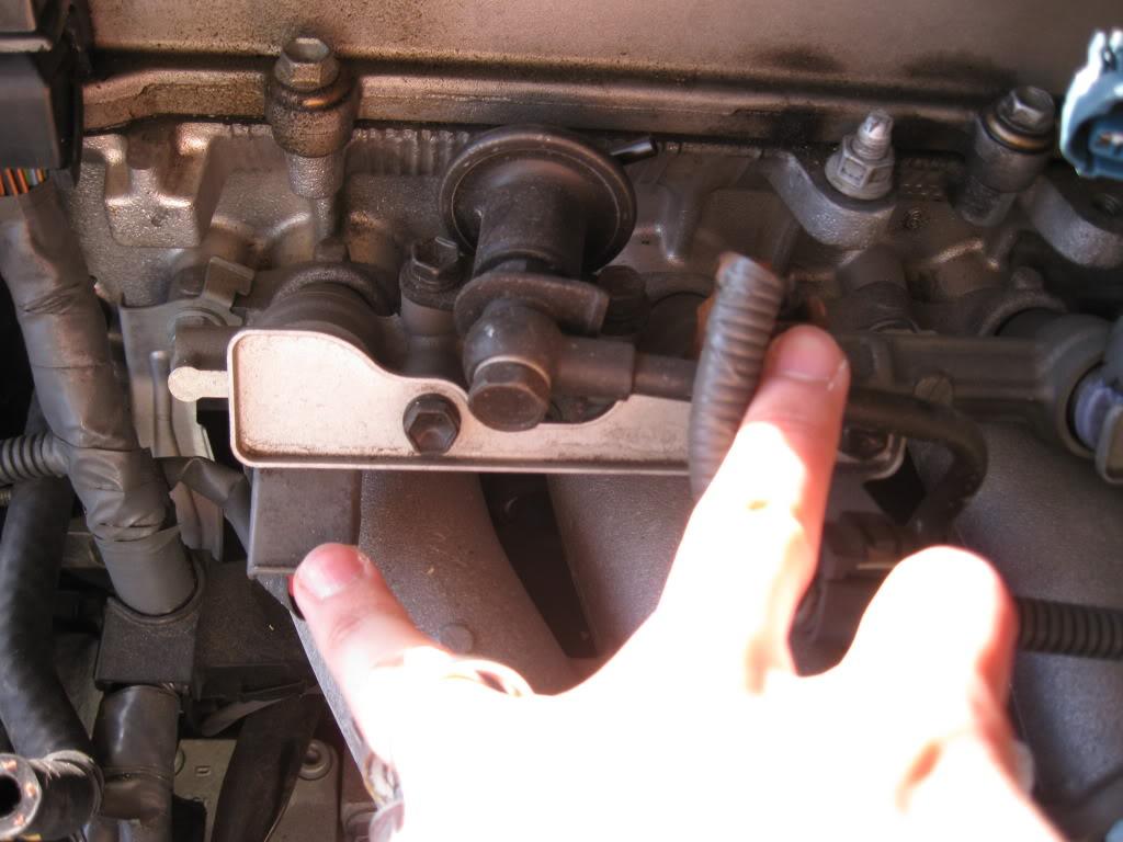
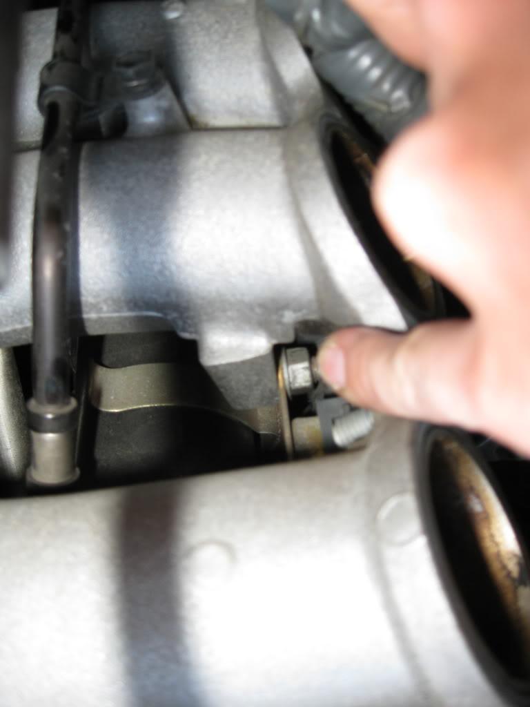
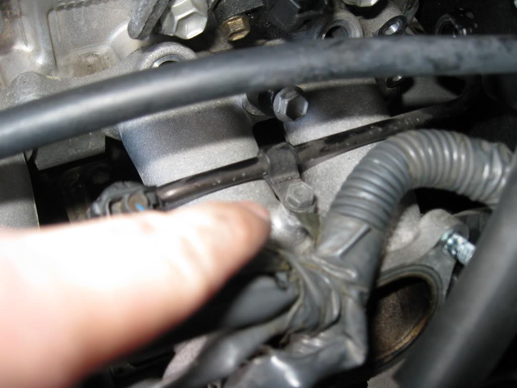
Next take off the the water/vacuum pipe near the front and the manifold stay.
Now deal with the engine wire harness. There are a couple of ground wires that need to come off, the harness itself is held on with two clips. These come off with a flat head screwdriver put in and lifted. Takes a bit, but you'll see when you try how they come out.
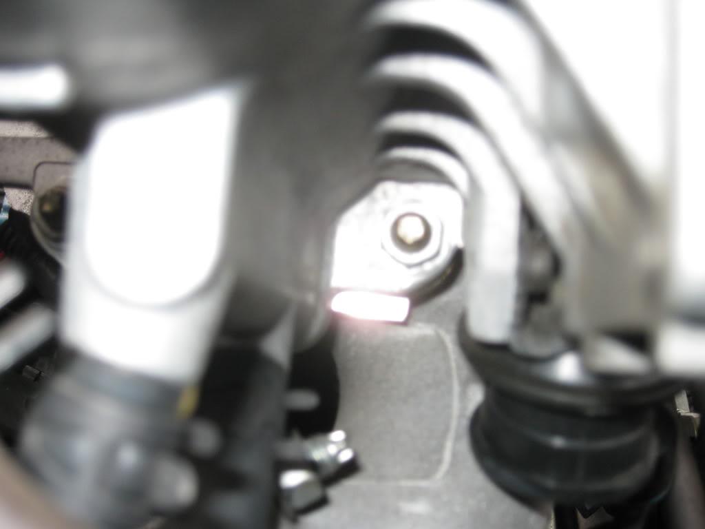
Next the upper chamber comes off by removing 5 bolts, 2 nuts. There is a hidden one near runner four that you need an extension to get too. If you don't get the engine harness off properly this part will not work.
It lifts right off. You should have a couple coolant hoses still connected to the IACV, disconnect them as needed.
All done that part.
Unclip your injectors, and x2 camshaft position sensors.
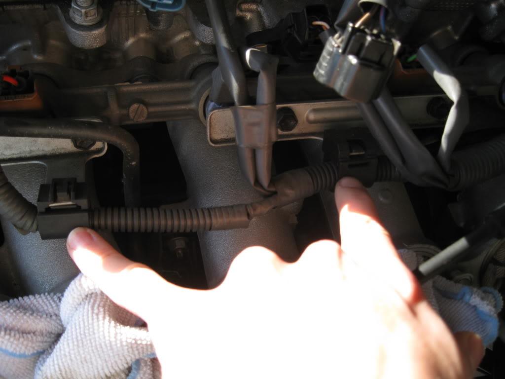
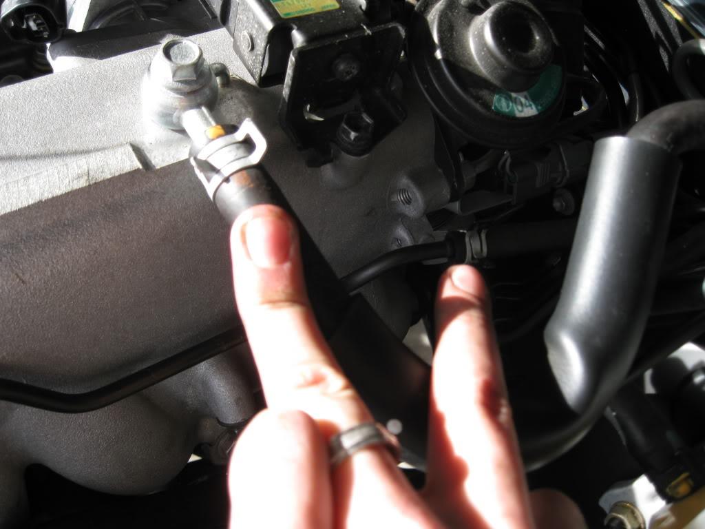
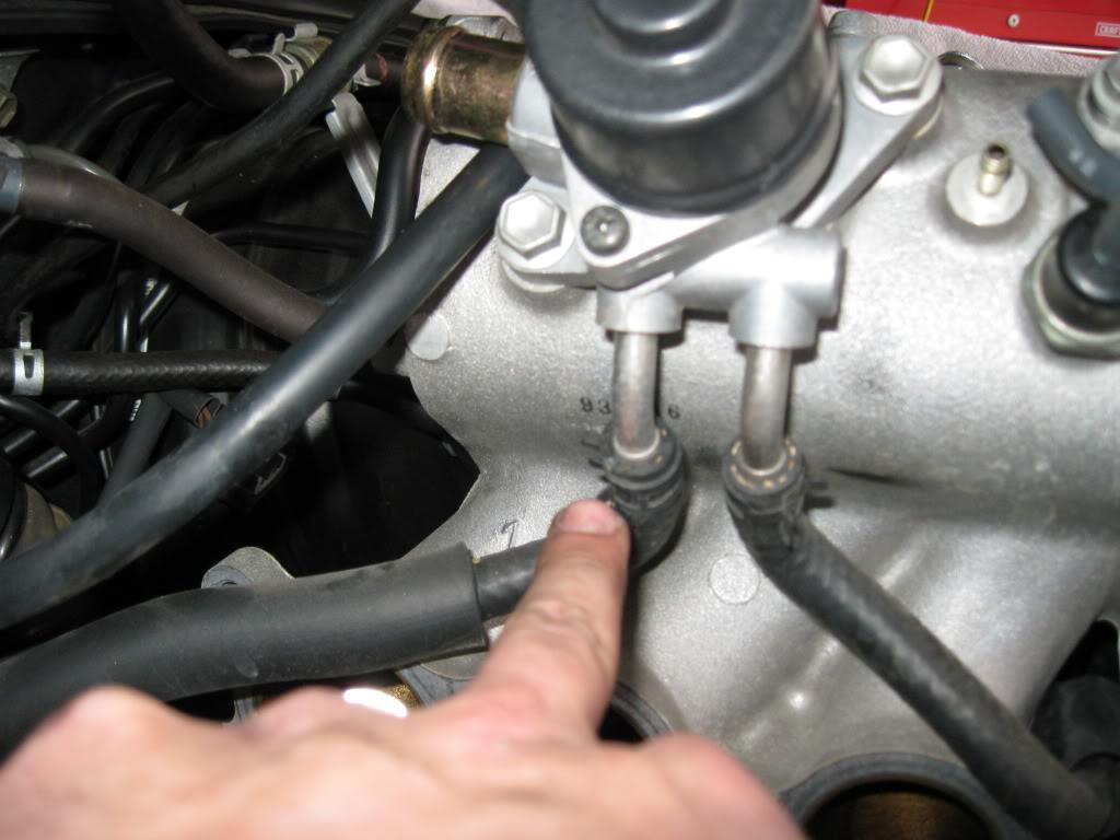
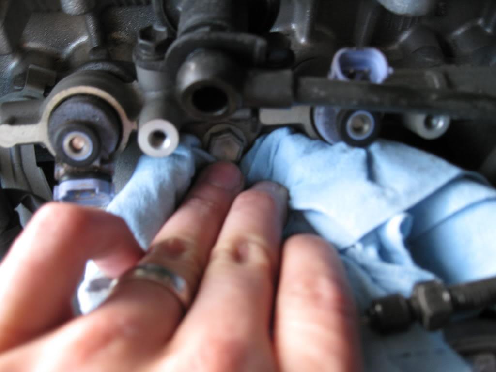
Next you disconnect the feed and return lines from the OEM line. Get shop towels ready to catch the run off. There will be a bit, but not an extreme amount.
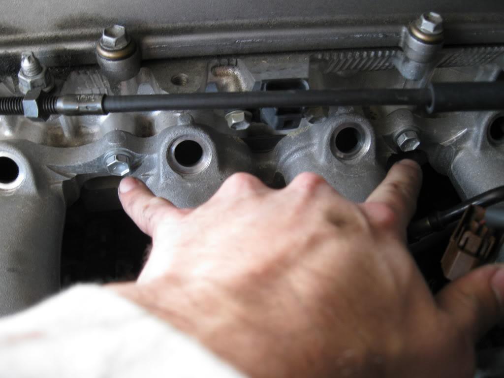
As the rail drains take off the x3 injector holders.
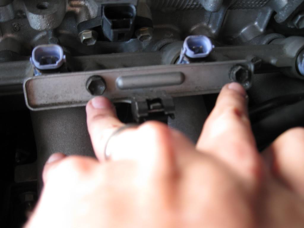
Then remove the rail/injectors themselves by taking off the x2 bolts and spacers.
Get a beer and get ready for the next part.
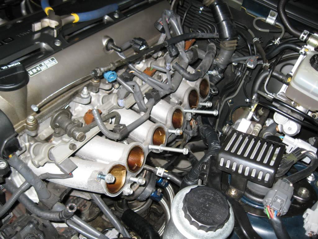
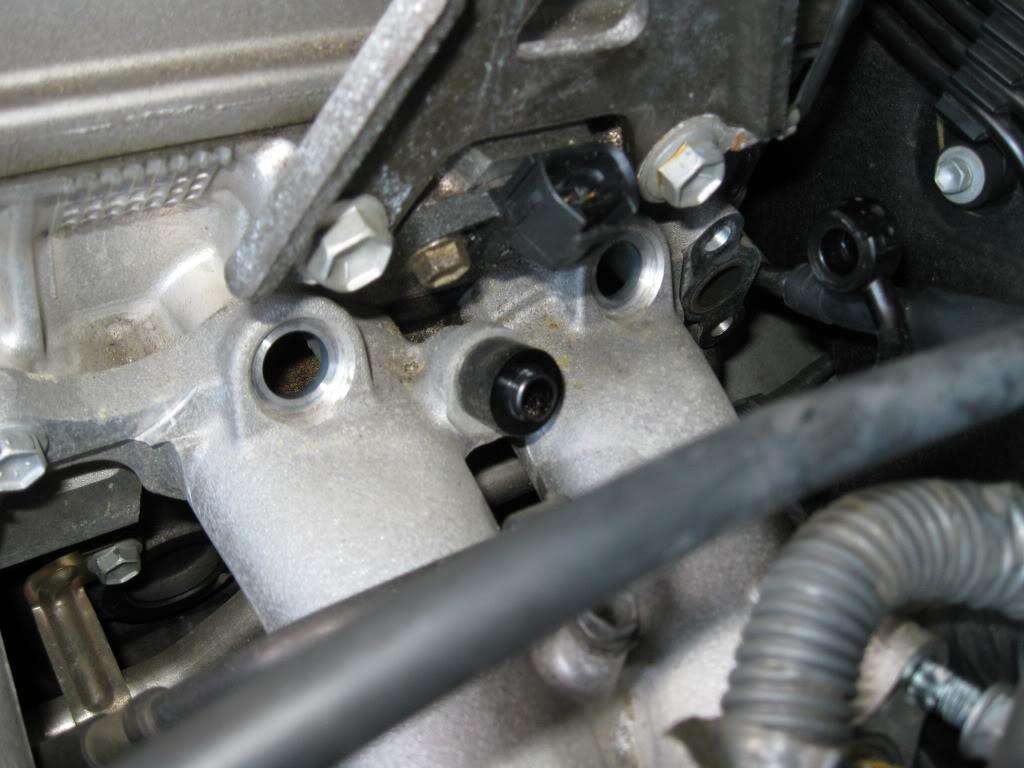
Next comes the lower runners. They are easier than anything else you've done so far. Take a few minutes to locate all the points where the runners connect to the head itself, as well as the electrical connections. Also, you will need to take off the bracket that holds the EVAP VSV and Pressure tank which is located under runner 5 and 6. Get everything unbolted first then gently remove the runners. If they don't come off with minimal effort you have missed a bolt/nut somewhere. I couldn't get shots of them all, there are a few underneath that are kinda hidden.
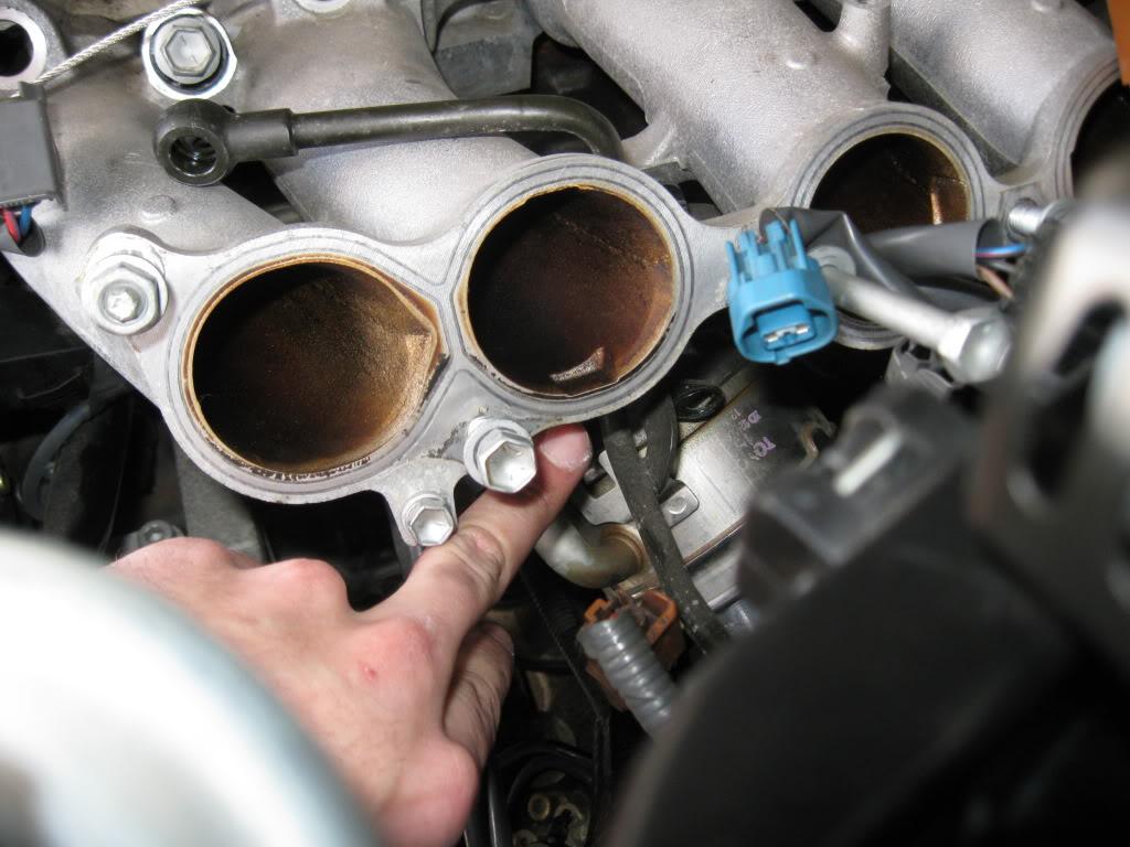
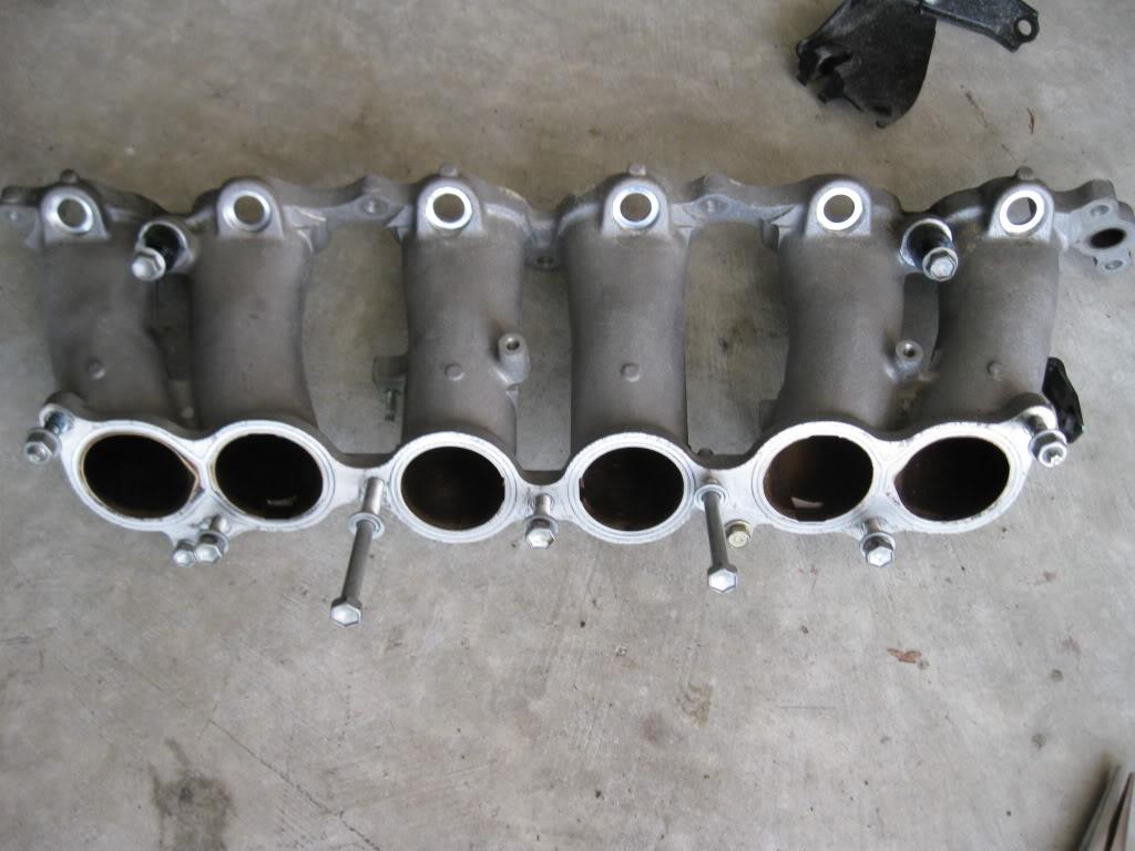
Damn that's empty now.
Good job! We now move into the trunk of the car. This part is important because if you disconnect the fuel lines now, and if you have a full tank of gas you will cause a vacuum and empty your tank. You need to open the OEM feed line up to the atmosphere to prevent this.
Pull everything out and expose your trunk. Remove your spare wheel as well if you still have it in there. You will need to remove some of the trunk panels later on so now is a good time to start on that.
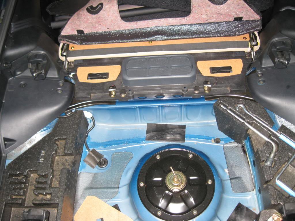
Remove all the panels on the left side of the car. Refer to the Body section of TSRM Volume 2 if you don't know how. It's pretty strait forward though, screws and clips.

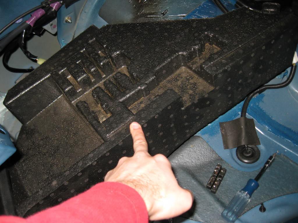
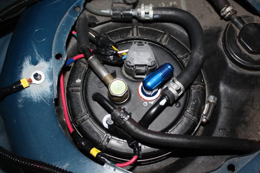
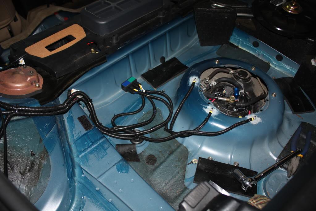
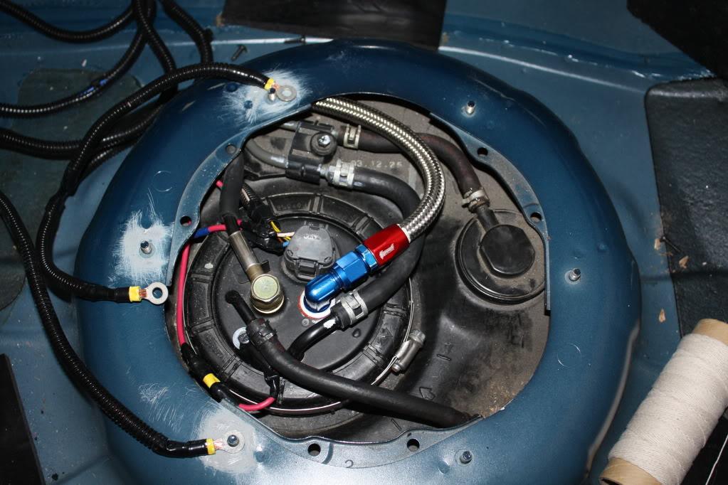
Now remove the fuel pump/tank cover and expose the top of the fuel hanger and plumbing.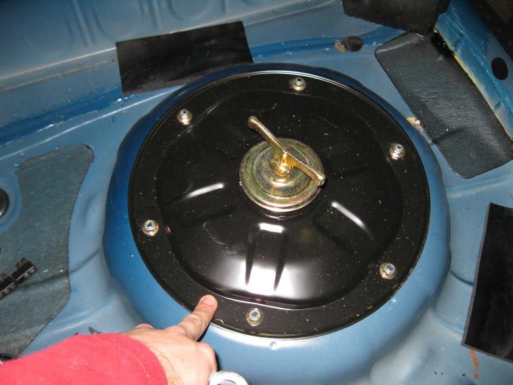
Open up the union bolt to equalize the pressure and head back to the front of the car.
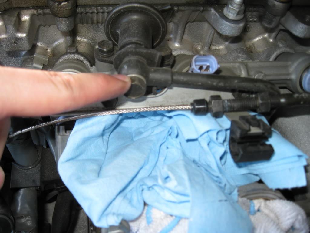
Remove the return line, it's easy as the hard pipe just connects into a hose via a clamp. This was the hose connected to the OEM FPR.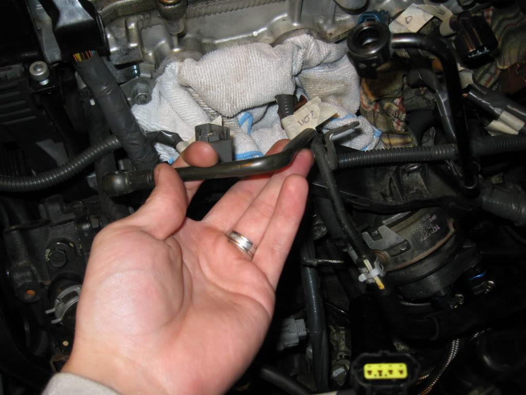
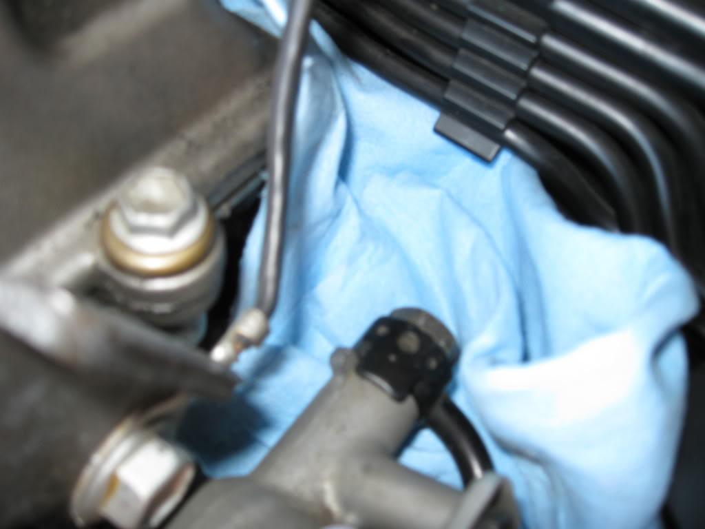
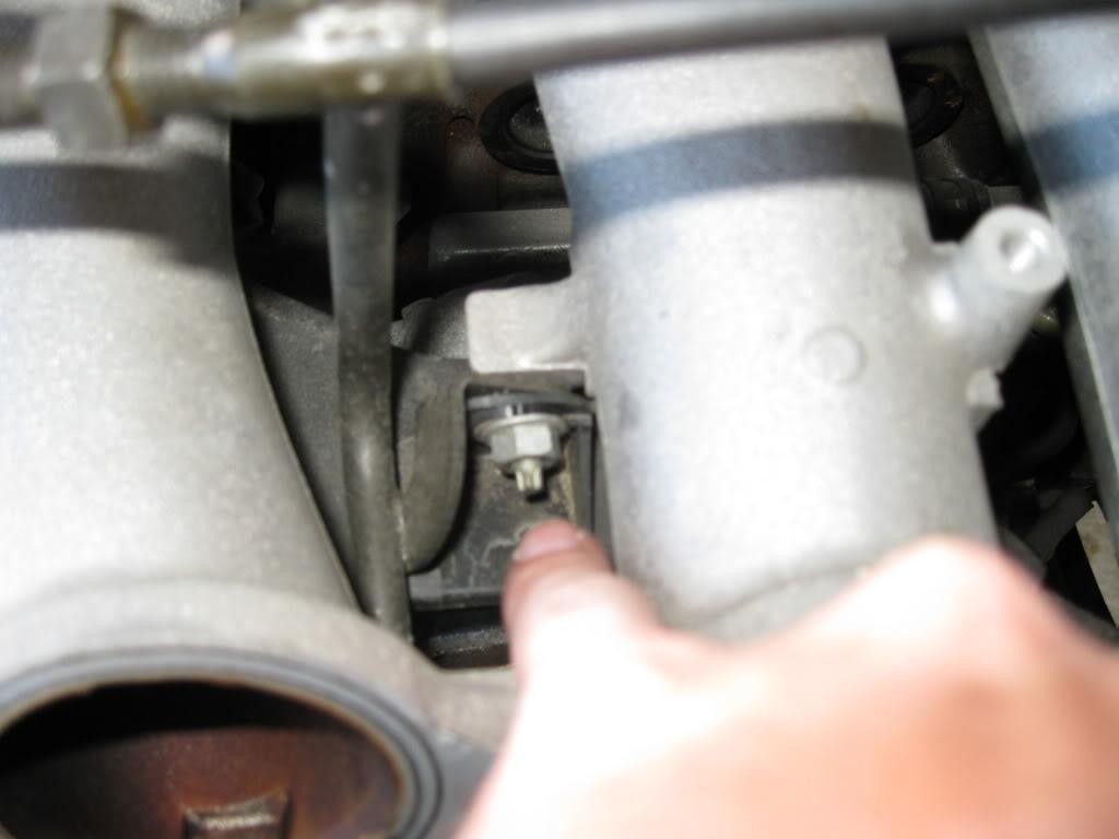
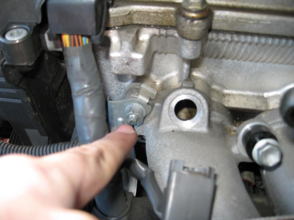
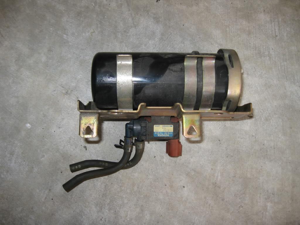
Prior to removing the feed line unbolt the fuel dampener.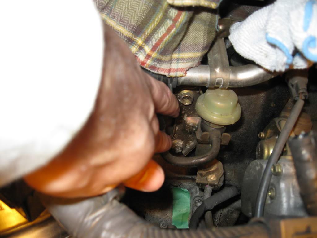
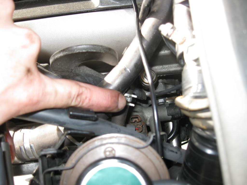
Jump under the car and locate your stock filter and feed line. If you are going to replace the old filter with a new one disconnect the whole assembly at the feed line. If you aren't disconnect everything from the engine side of filter.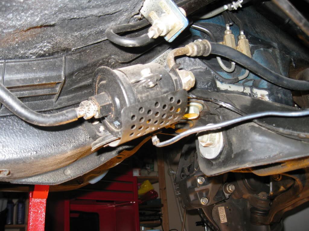
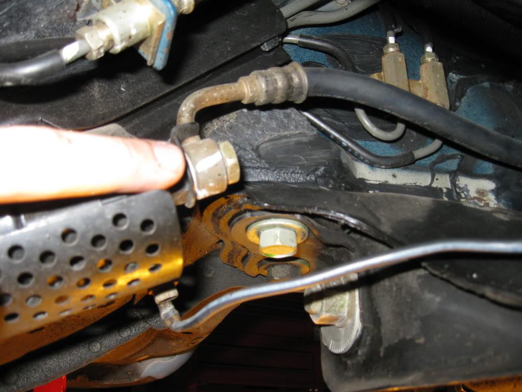
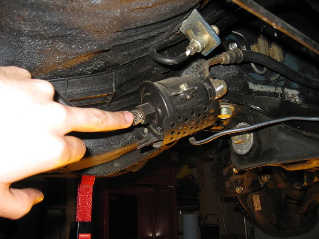
If you are going to put a new filter in undo the ground wire, and two bolts holding the bracket to the car.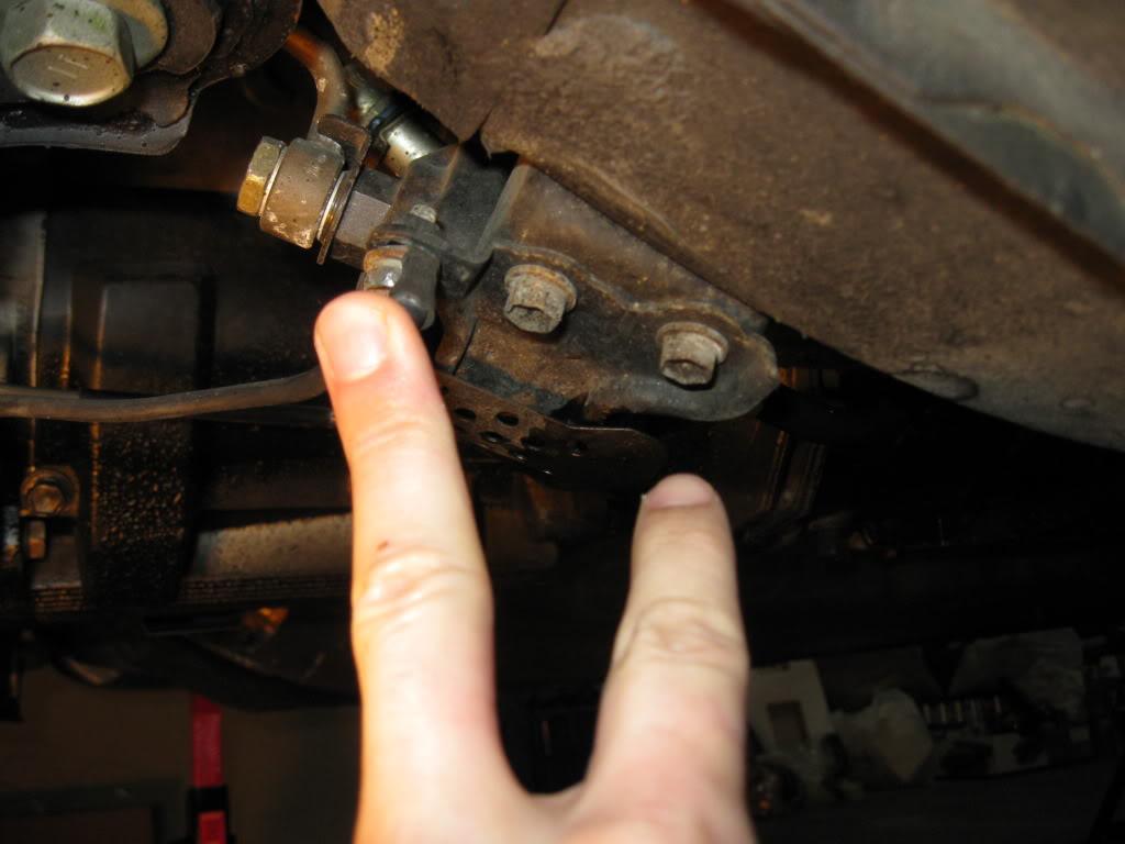
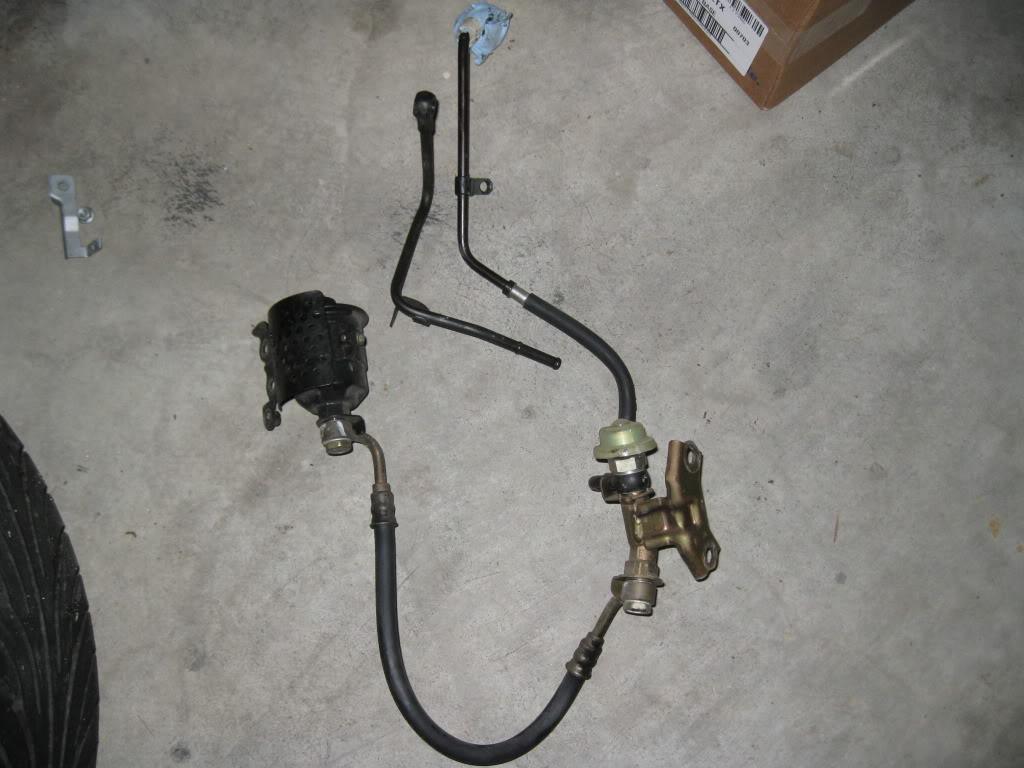
That is everything removed on the intake side, as well as the unneeded OEM lines.
Fuel Pump Modification
In order to run dual pumps we need to add a new pump since there is only one in the tank to begin with. You can achieve this pretty easily and have two options really.
Option #1 is to purchase a new, already modified hanger which is intended to support multiple pumps. This option will remove the stock hanger all together. This option will cost you a lot more, figure to budget ~$600 or more. Also, these hangers do not incorporate the use of the OEM feed line as far as I've seen, nor the return line so you will need to purchase more fittings and more line. I would estimate an additional 30-40 feet of line, and 6 10 more fittings depending on your set up. The pro side to this is there is really no stress or worry regarding wiring, fuel lines etc. It is a very good option if you can work it into your budget.
An example of this can be found from MVP (Triple Denso) and PHR (Triple Walbro). Link to MVP Website here.
Option #2 is to modify your existing hanger to allow for the second pump. This option cost basically nothing to do, but you are modifying your OEM hanger for something it isn't intended for. That being said, this set up has been used a countless number of times with complete success.
I went the route of Option #2 in my build, however, I will be switching my hanger out to a pre-fabbed one down the line without a doubt. Also I'm unclear how Option #1 would effect the wiring aspect of this How-To, but I would expect it to be nearly the same.
This what to do in order to modify your existing hanger to use dual pumps.
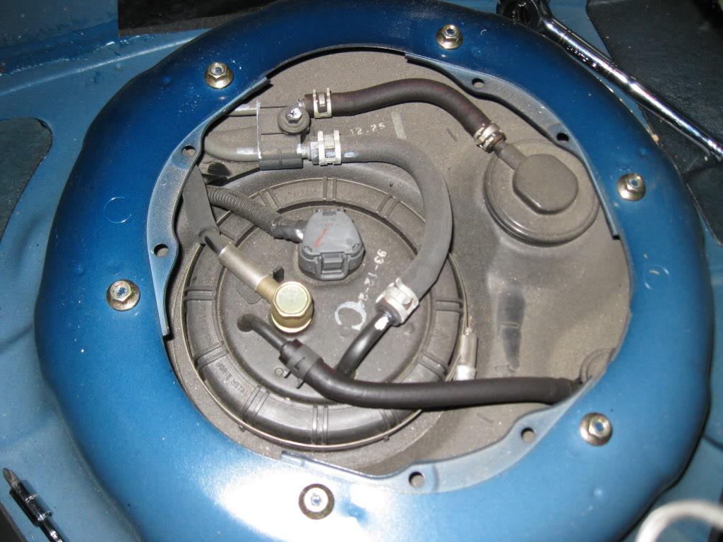
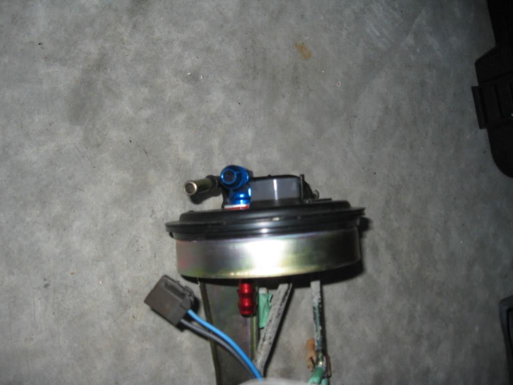
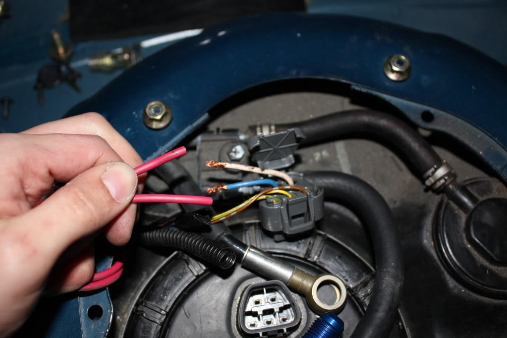
First thing is to disconnect all the hoses, the electrical connector for the top and the worm clamp around the cap.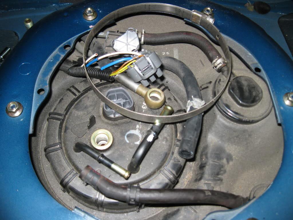
You will need a tool to remove the hanger cap. It is on there antichrist hard and cannot physically be done by hand. The OEM tool is around $200. There are many tools out there that will work. You will note a wood clamp in the picture, I used that to get it off, but switched to a different tool to get it back on since it didn't work that well. Check your local auto parts store for a tool that will work.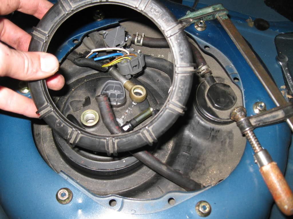
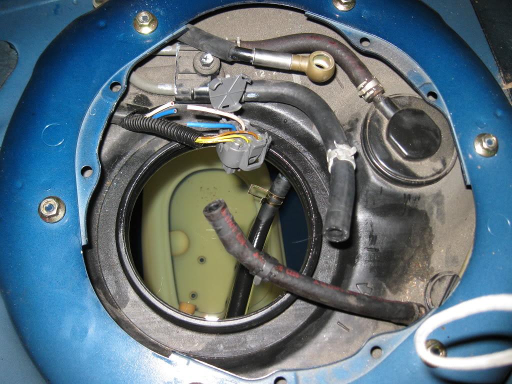
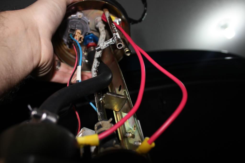
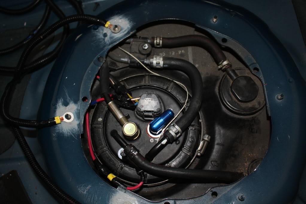
With that off the hanger comes right out. Here is the inside of the tank.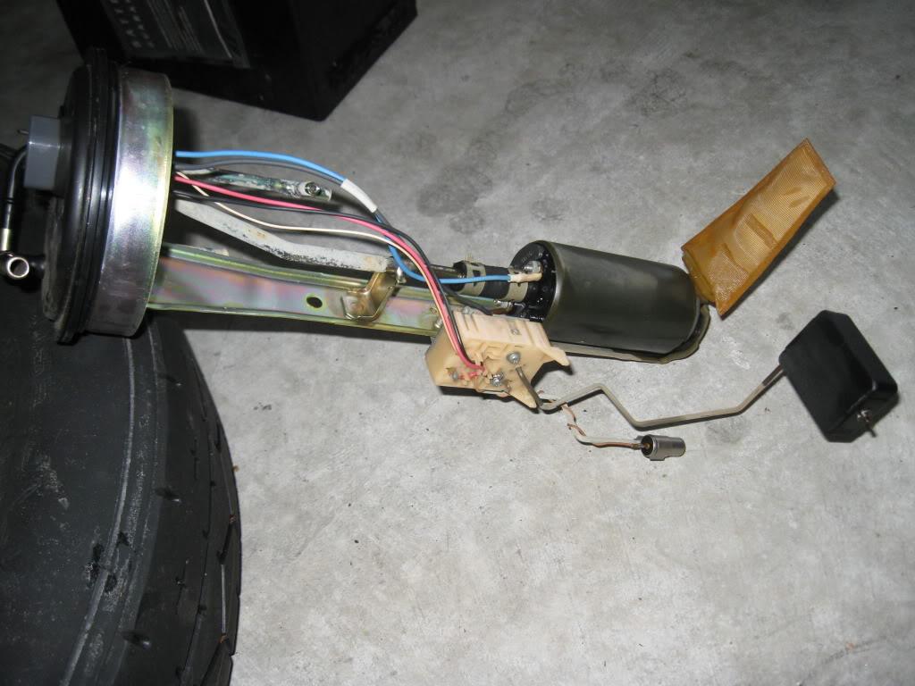
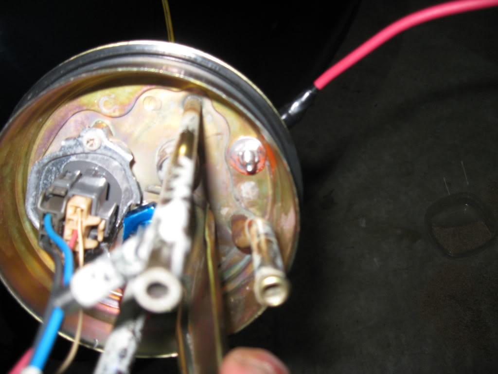
I went through a couple different setups for grounding etc. but I'll just show what I ended up with. The key concept is that you will utilize the OEM Power AND Ground wires as 12v lines from now on. As a result you need to ground the pumps to the chassis. I opted to ground the pumps to the grounding screw at the top of the tank, rather than to the hanger.
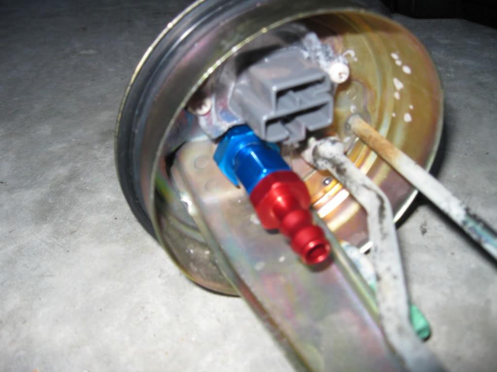
You will need to drill two holes, the first is for the bulk head fitting. Measure the fitting you have and get the closest size drill bit to that as you can. A bit smaller is better I would say and open the hole up with a dremel bit by bit until it is snug. There will be a washer on both sides of the bulkhead, each siliconed on the side that makes contact with the hanger, with the bulk head nut going on next. Once that is on the twist tite fitting goes on the bottom for the feed line for the second pump.
Same process for the ground screw is to be followed here.
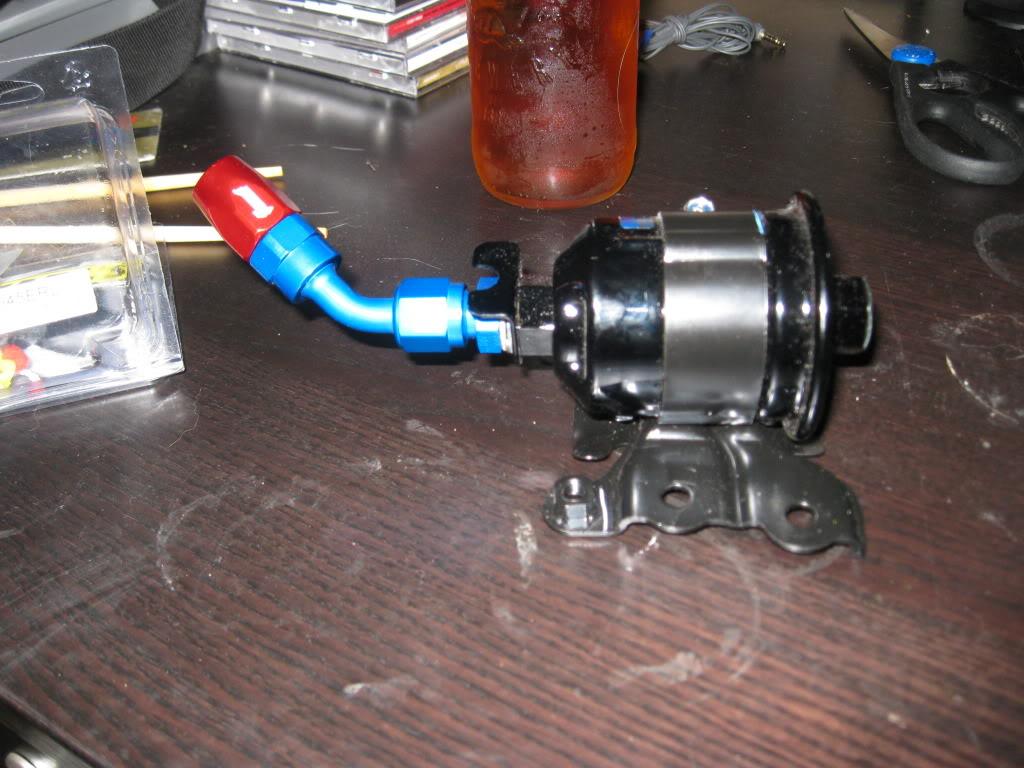
The two pumps are aligned on top of the other, secured by clamps with some material between the two to reduce vibration. I used a piece of think hose designed for submersion in fuel. This is where the pump wrap would be used from a vendor kit, or if purchased separately.
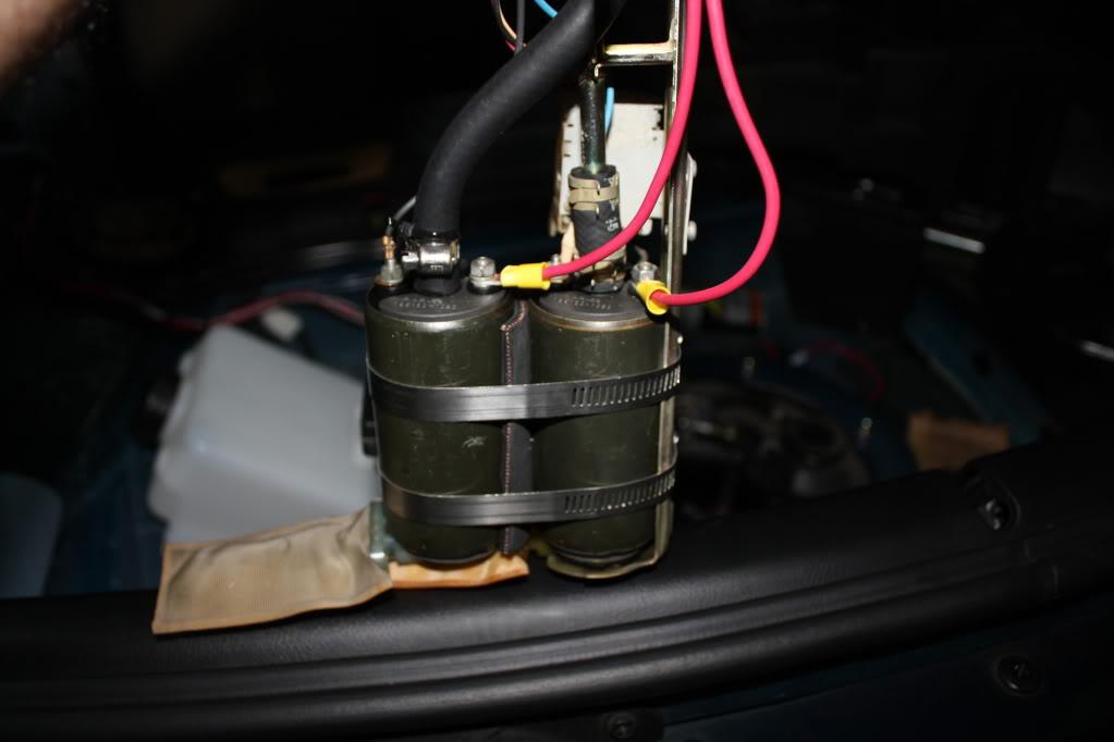
The ground wire connect to the grounding screw up top.
Wiring related to the power to each pump will be covered in the next section. This will allow for proper function of each pump on a modified OEM hanger.
Wiring
The next step is wiring the pumps up so they work properly, and safely!
Following this diagram is the preferred method for wiring, is proven to work and is effective.
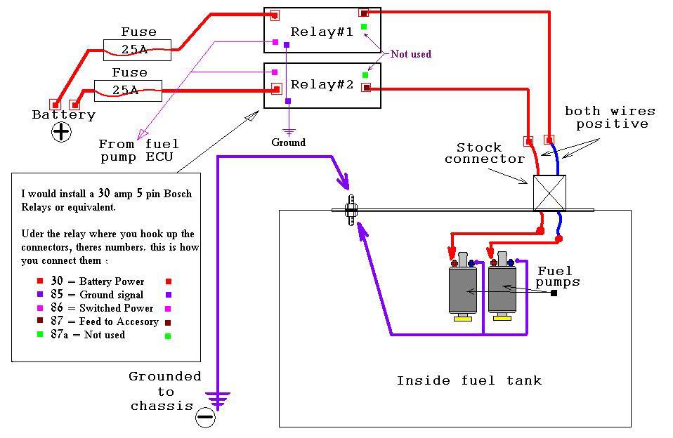
The way this works is simple. Each pump is powered off a relay, which is only activated when the vehicle is on. Each relay gets power directly from the battery. A switched source is obtained for the relays, and when on power the pumps. If you are in an accident the pumps shut off using this method. Hard wiring the pumps to the battery is bad, imagine your in an accident, your car is off and your pumps keep blasting fuel into your engine... not good.
You can adjust this schematic as needed to fit your project the basics should remain the same. I added in two switched power lights which attach to warning LED's, one for each pump. This wire is spliced in on the accessory feed line. The idea is, if a fuse blows, the relay dies as does the light, which in turn visually alerts me to a pump failure if I didn't notice the fuel pressure drop or some other sign. Kill switches can be added in to stop the relays from switching on at all if you are ultra tight on securing your car. Best way is to put a switch, or switches on the 12v switch power line somewhere before the relay.
Some tips for wiring:
If possible get different colored wire for each pump, if not available color code each wire. It will allow for easier troubleshooting if something isn't proper.
Solder connections where possible. If wire connectors are used ensure proper connection is being made.
Take your time, attention to detail here will make your life easier in the long run.
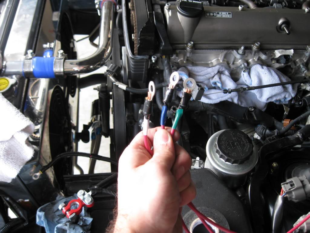
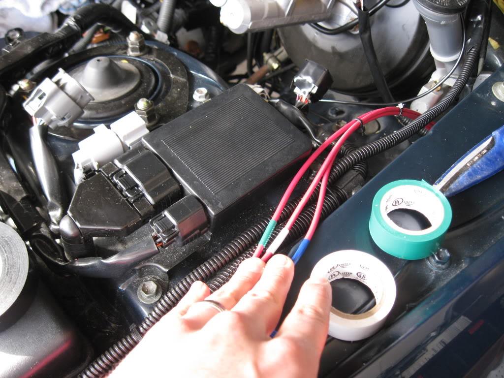
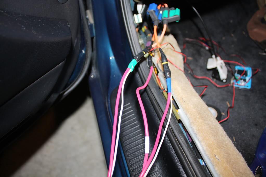
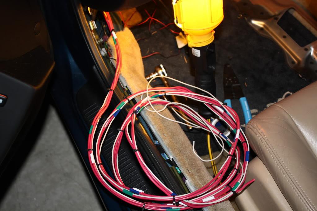
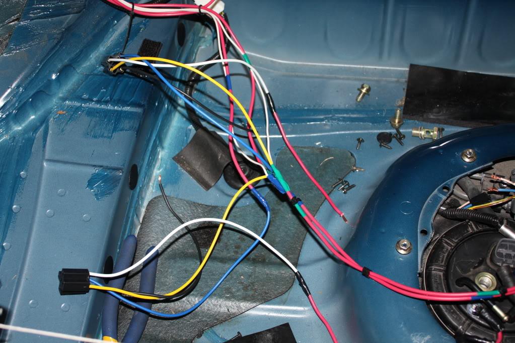
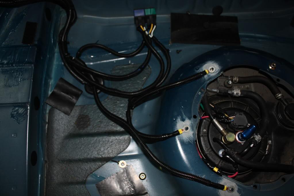
These pictures show three power wires, only two (Green/Blue) are for the fuel pumps. The white wire is for the Meth kit. Just an FYI.
Start at the battery end and work your way back, just makes the most sense to me. Start out with prepping the 12v constant connections.
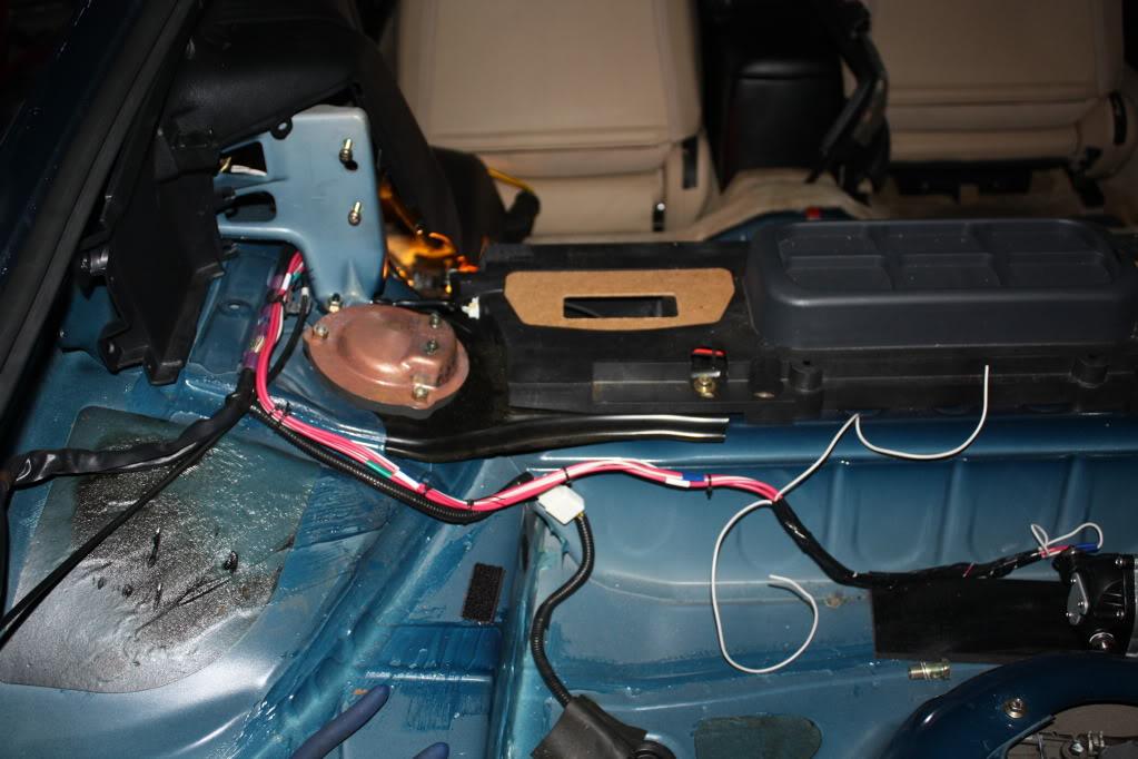
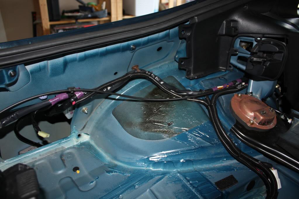
Test run the lines into the vehicle. I utilized the grommet behind the wheel well.

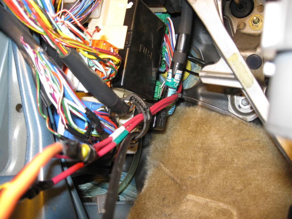
Into the car, I recommend zipping everything down as you go, you can always go back and change it later, but keep it tucked away makes life easier. Note: Plan your routing ahead of time, it'll save you some headaches! I put my fuses here, they are with the other fuses and easy to get at.
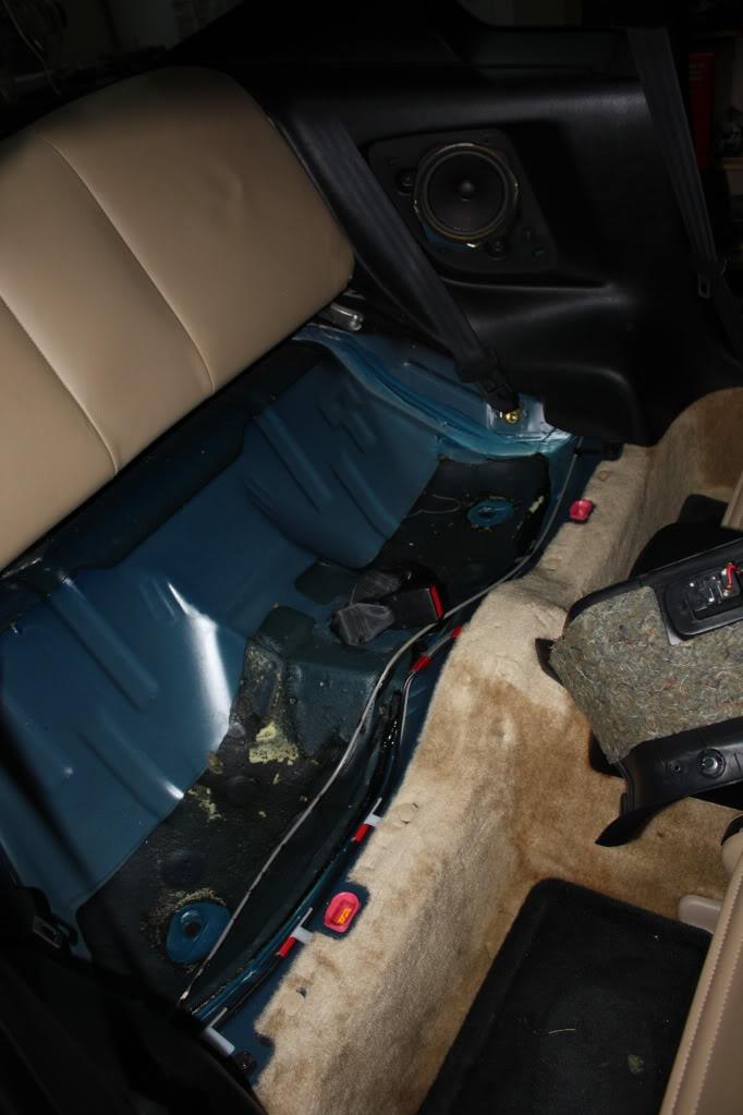
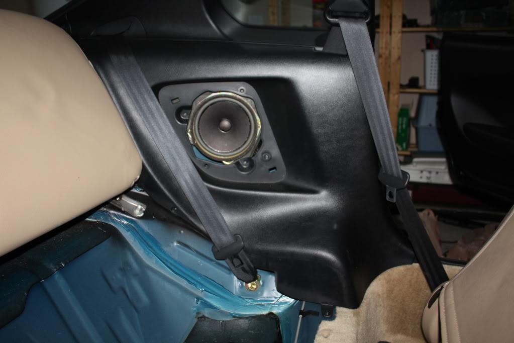
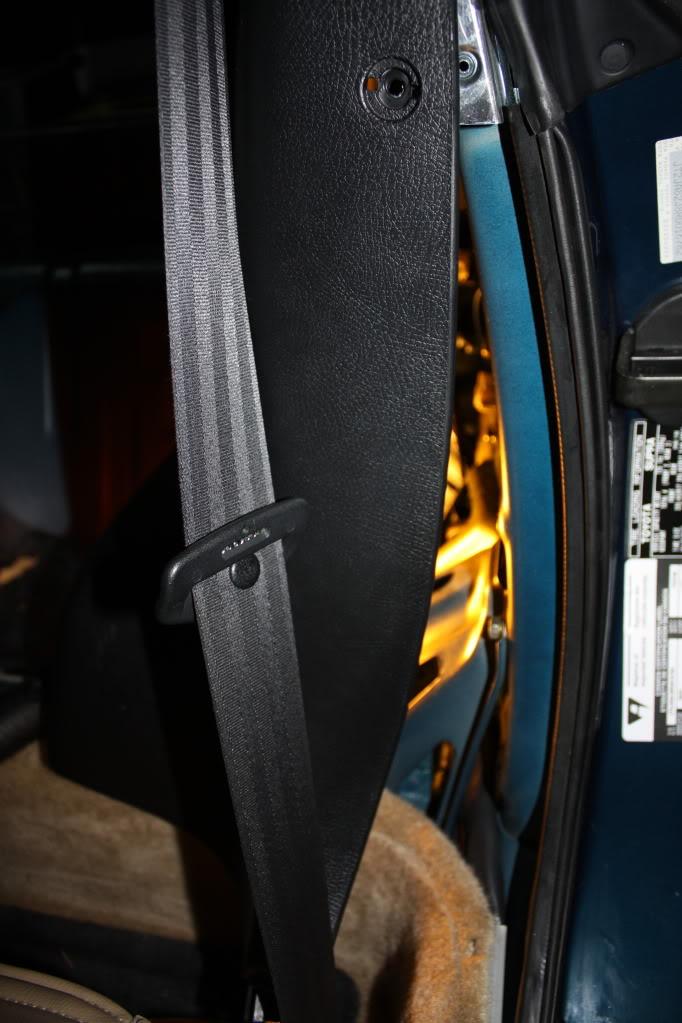
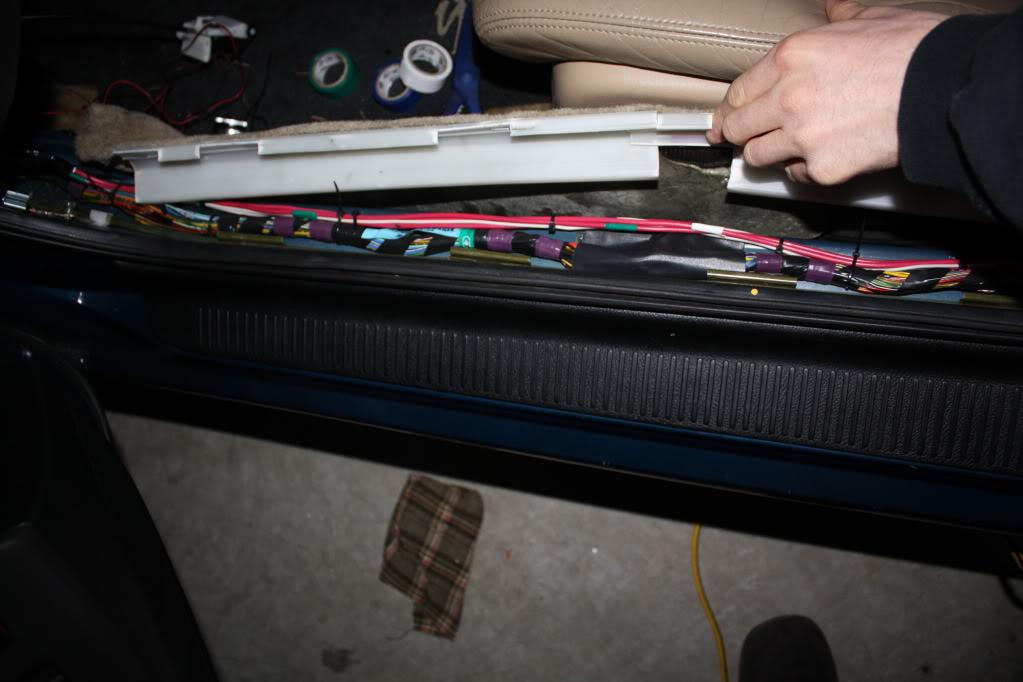
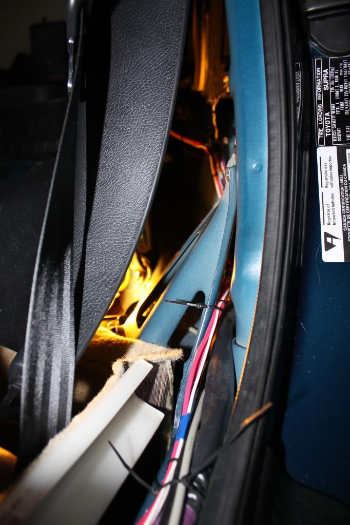
Next figure out how you want to route the lines to the trunk. I wanted a clean install so I went under the floor carpet, behind the rear speaker and through the back pillar. How you route is up to you, here is how to do it the way I did.
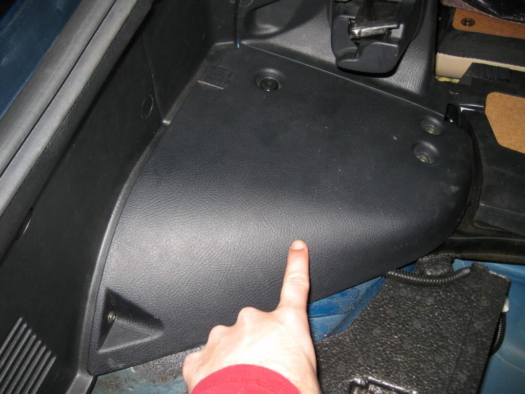
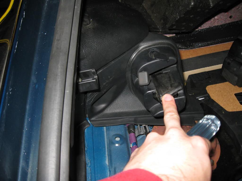
Lift the carpet up along the driver door all the way to the end. The trim should already be out of the way as you'll need to do that to gain access to the fuse panel area.
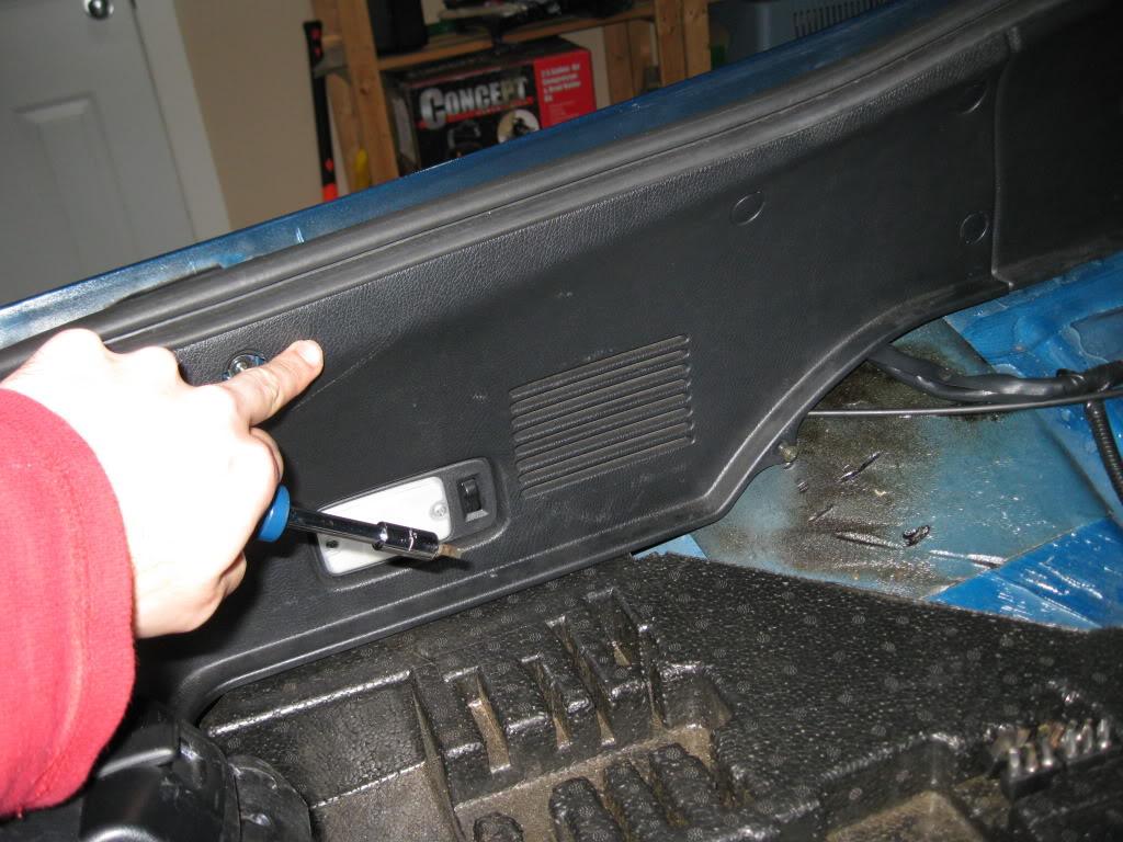
Next take out the back seats. To do this pop the bottom half out, they aren't bolted in. Once those are out you will be able to see four bolts on the top half that folds. Once those are gone the top half slides out. While you are back there remove the speaker grill, two screws in there, as well as the two screws on the bottom of this body panel which will allow for the piece to flex out.
With that gone you can prepare your pump wire loom. Decide now if you are going to do warning lights so you can wire them in now, and save the time later.
Pump wires, with warning light power wires.
Lights marked.
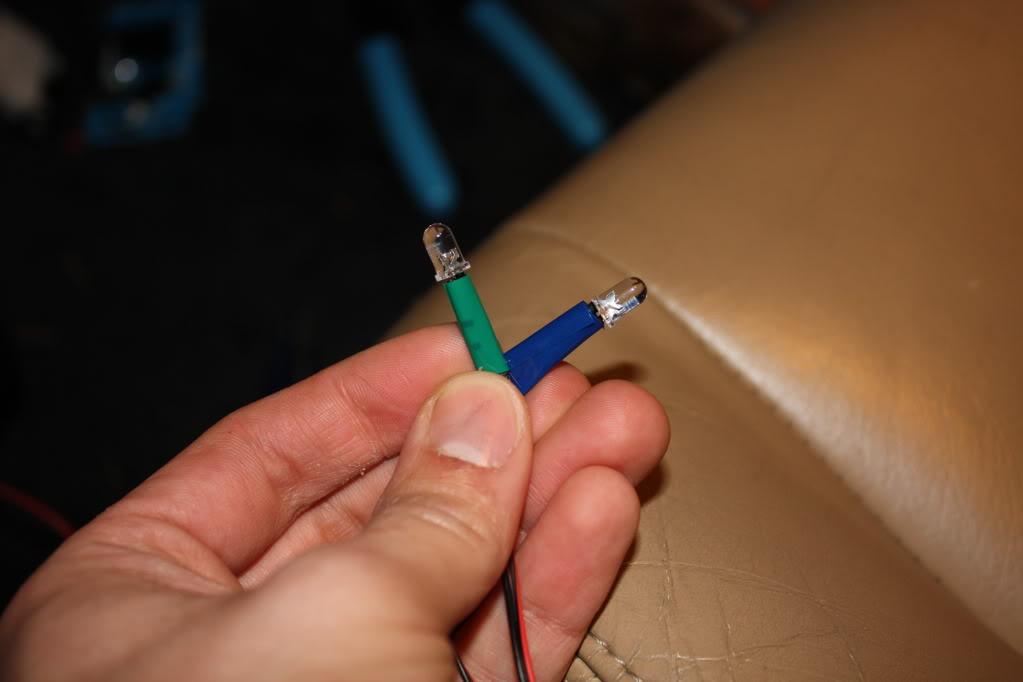
Final loom ready to be fed to the trunk.
Route the wiring along the base of the car, into the rear area, and under the back panel.
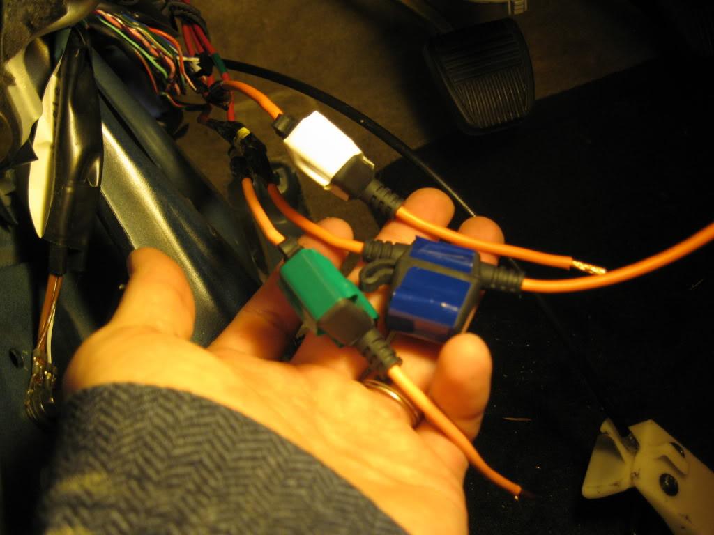
Now you have your 12v constant wires into the trunk area where they will meet with the relays. Here is where it can get confusing. Take your time, and pay attention to the relay pins etc. If you can get pre-pinned relays like shown here it's one less thing, but ensure the colors on each one match the other.
The first thing I did was wire the 12v constant to the relays (blue relay wires). Also here I extended by 12v switched wires (white relay wires), and lastly the accessory (pump) power wires (yellow relay wires). Also note the LED wires are spliced into the accessory feed.
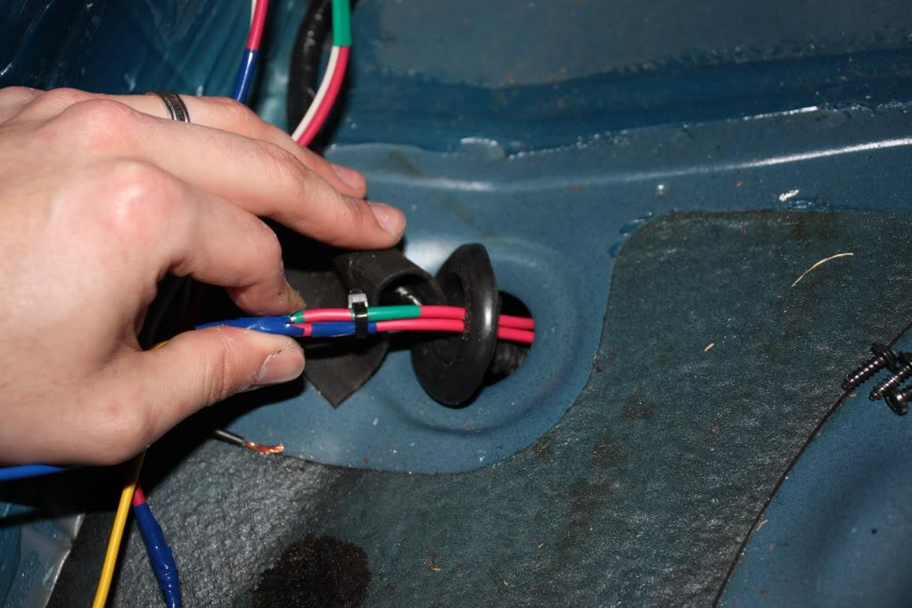
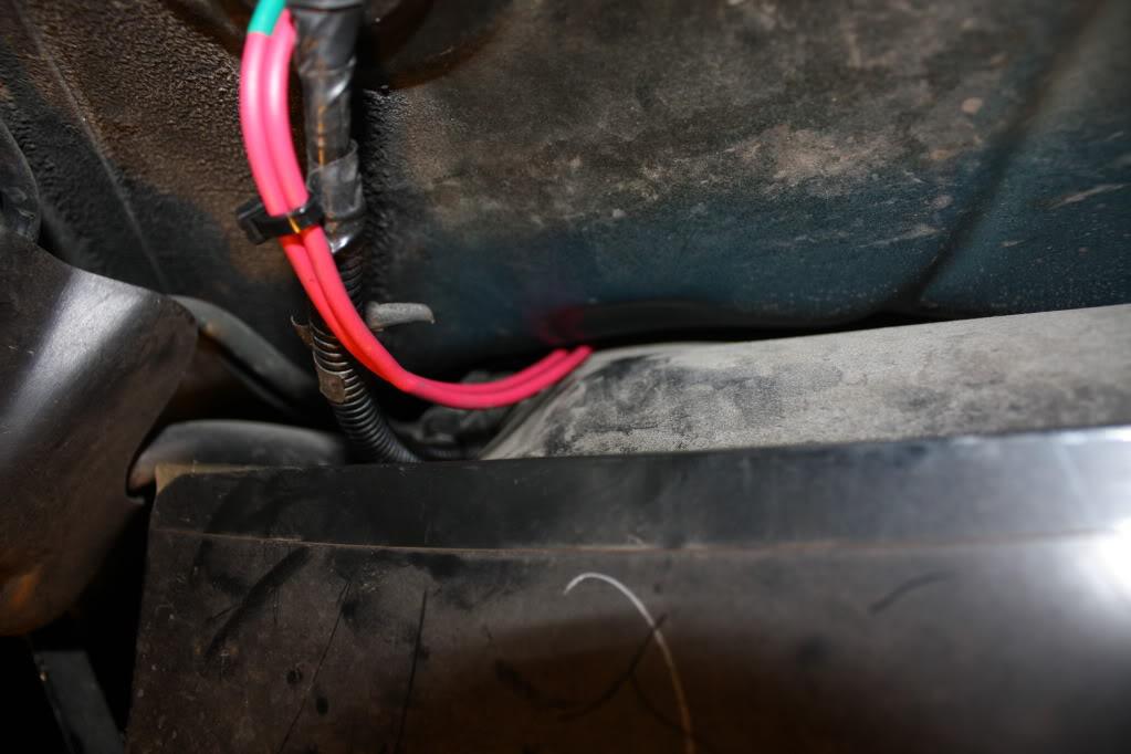
In keeping with a clean install I routed the pump wires through the OEM grommet, underneath the car/tank and into the pump hanger area. Note: I already had my rear exhaust heat shield off. It will need to be removed if you follow this routing.
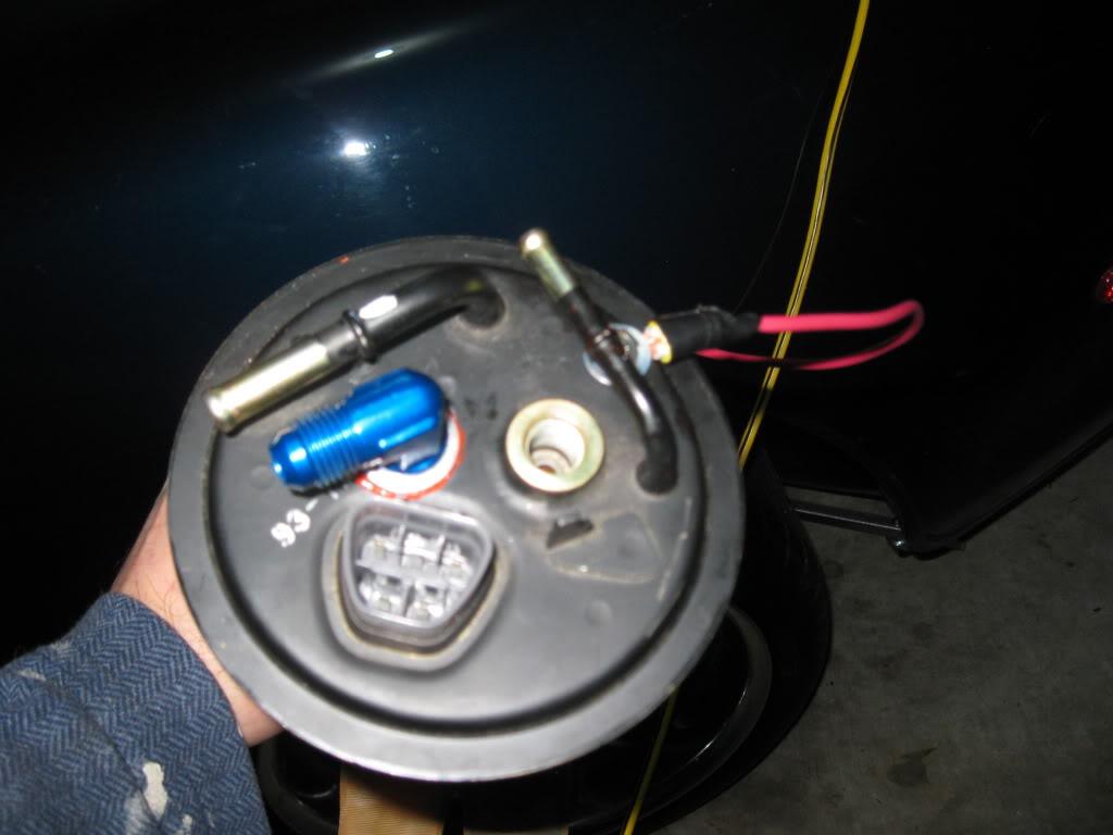
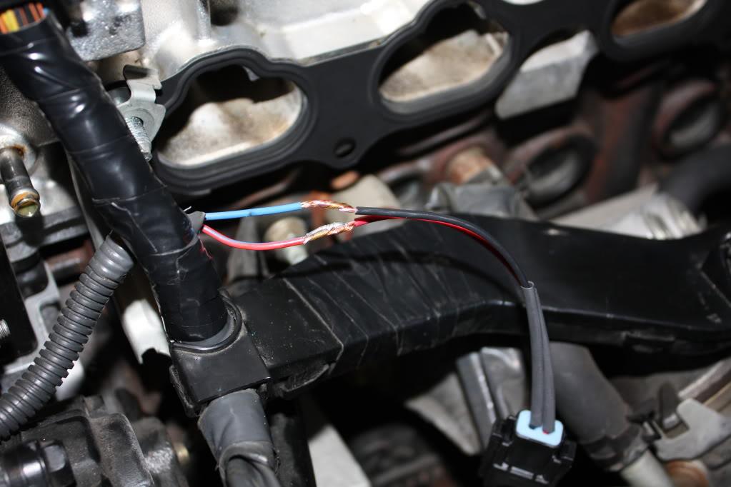
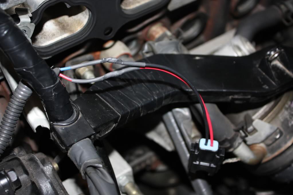
Once done I prepared the OEM power/ground wire to accept the new pump power. It doesn't matter which goes to which. Solder a power wire to either the blue or white OEM wire and cover.
Also, I routed my hanger ground back out using the same path as those power lines. I wanted a tight seal on that cover which wouldn't be possible if you put the ground wire on from the inside.
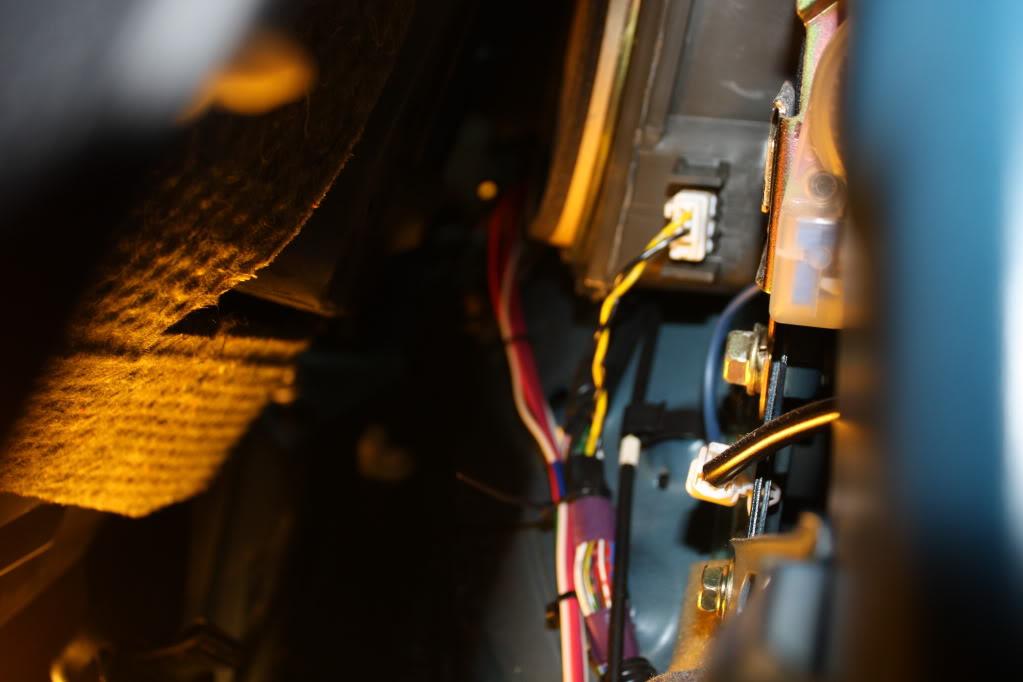
Next wire up your 12v switched power. You are going to pull this from the Fuel ECU. Ensure your vehicle doesn't have the 12v Fuel Pump Mod done. If it does, put it back to stock. This is the wire you are looking for, it's blue/red on 1993-1996 MKIV. 1997-1998 is black/red.
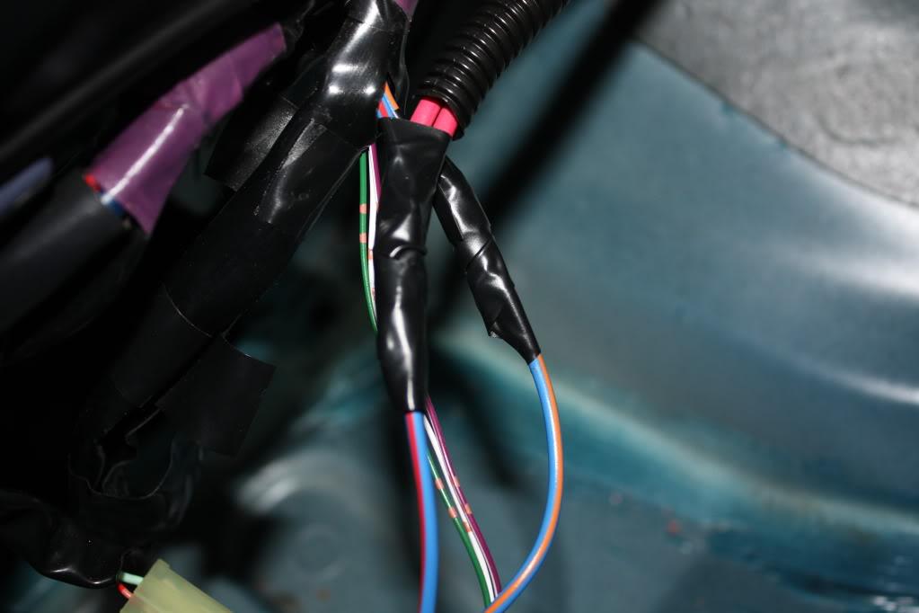
Splice your 12v switched for each relay here.
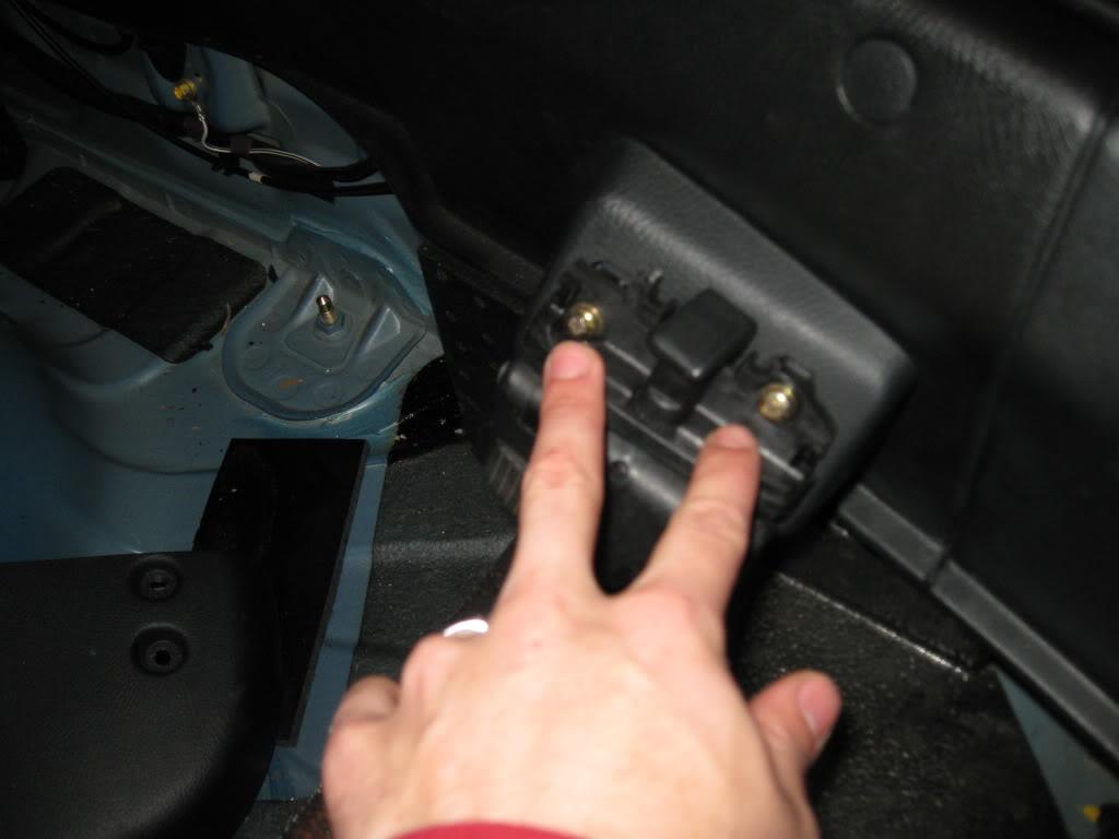
The last thing to do is to mount your relays and wire your ground. Then cover up if you want to make it look clean. Here is how mine turned out. Each ground has it's own spot, probably not required but why take the chance.
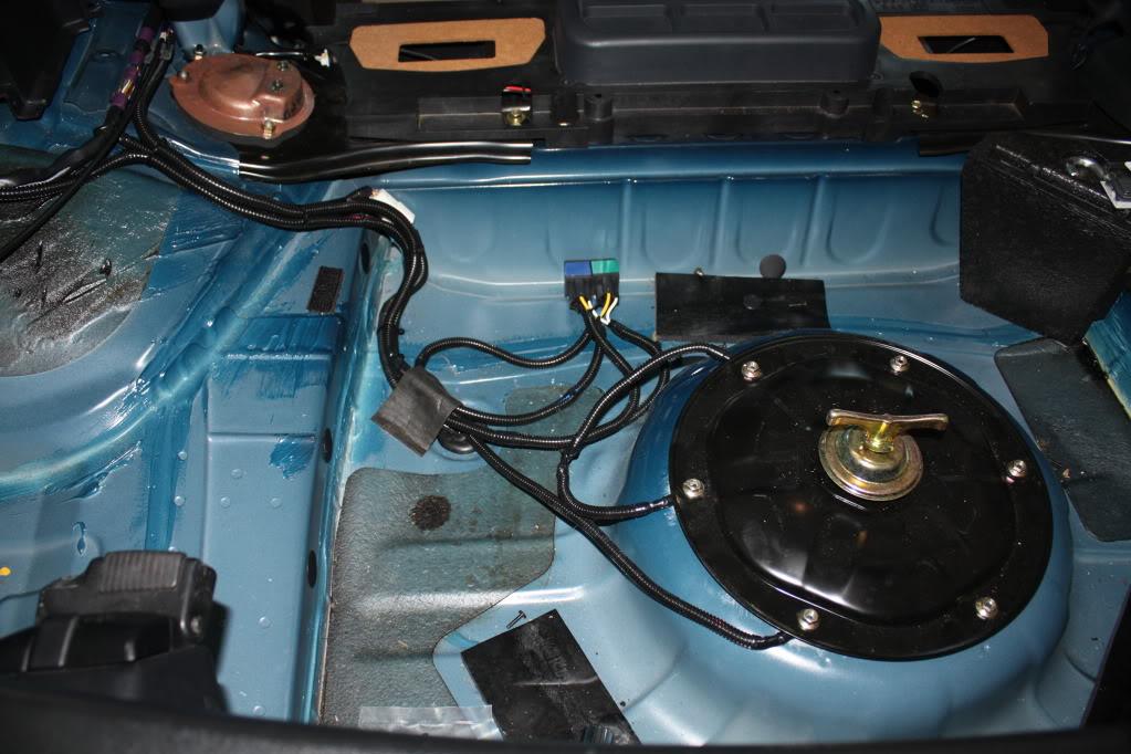
Wiring finished!
System Install
As previously stated we are doing a dual -6 AN feed system with a single return. We will be utilizing the OEM feed line and the OEM return line. Both of these are the same basic size as a the -6 AN line we will be installing so there is no worries of pressure drop or variance. Below is a basic (very basic, MS Paint FTW) of the plumbing routing that we will put in.
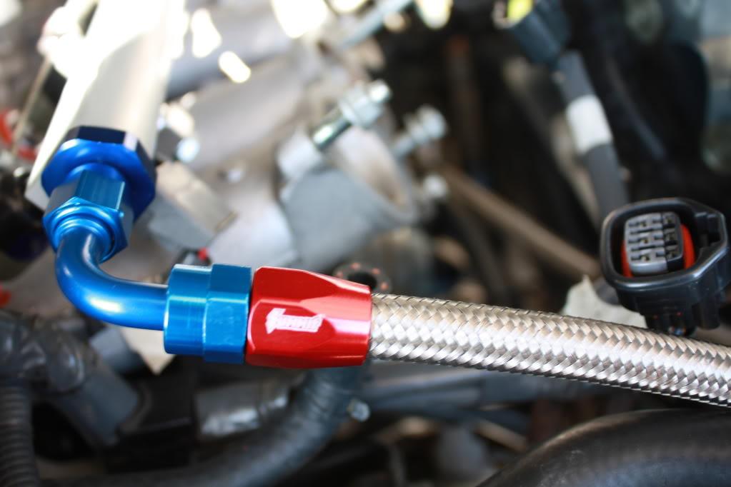
Take your time and measure your lines out proper to prevent head aches later on. The following is the steps to properly assemble the fittings on the lines that will not fray, or leak.
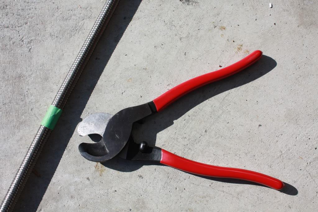
Once your line is measured out mark off the length with masking tape. Go around the line a couple times, but not too many as the fit into the fitting is already snug. I used round wire cutters for the job. They are cheap and wicked effective. No worries of debris in the lines.
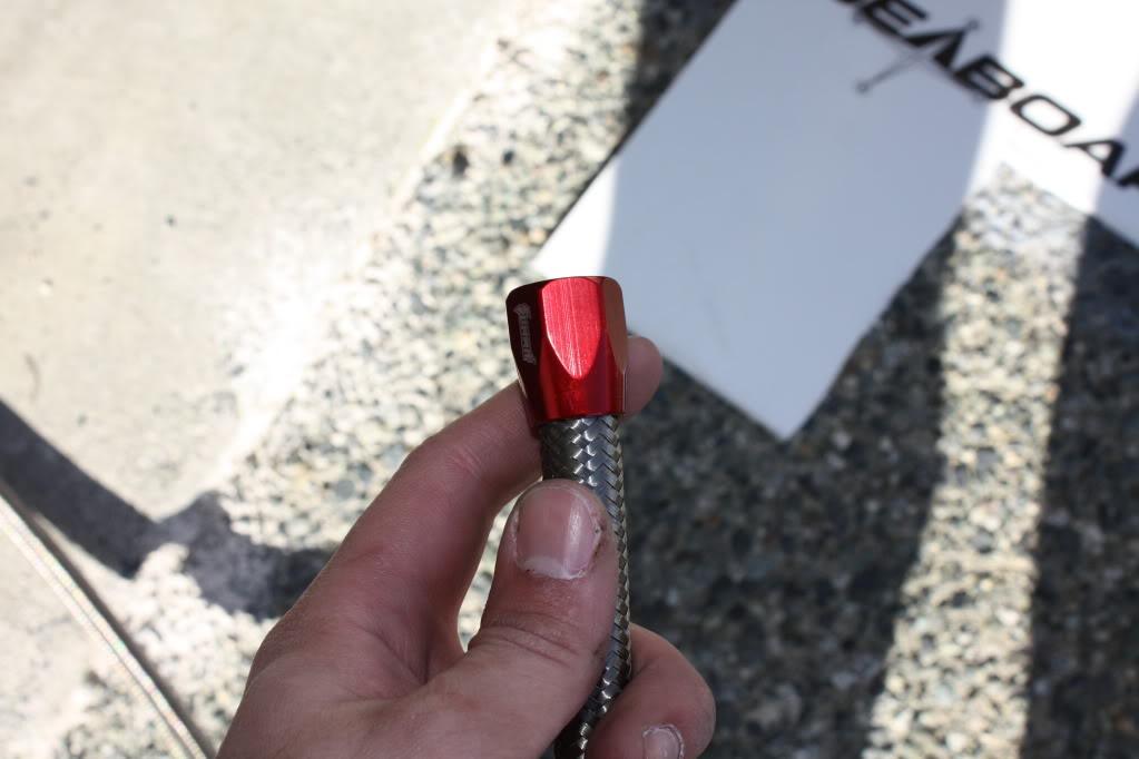
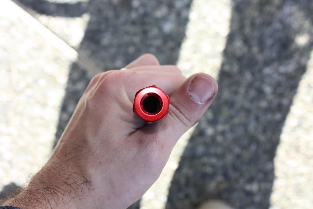
Once cut slide the line into the end of the fitting. You have to take it apart as you can see. Get it all the way to he end. There are threads inside, so twist it as you go.
Next screw the connecting end into the line. It will start easy and get a bit harder. Most can be done completely by hand, however if you need to use a wrench cover the fitting with tape to prevent scratching. Screw in until tight, and all the way in.
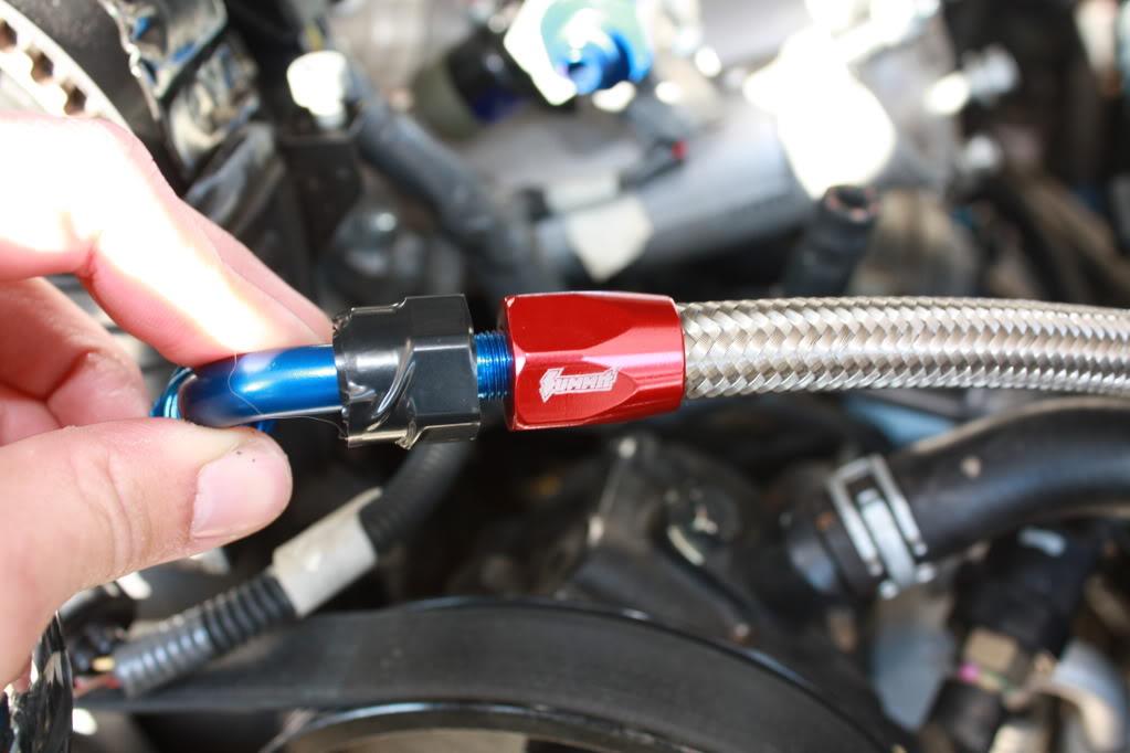
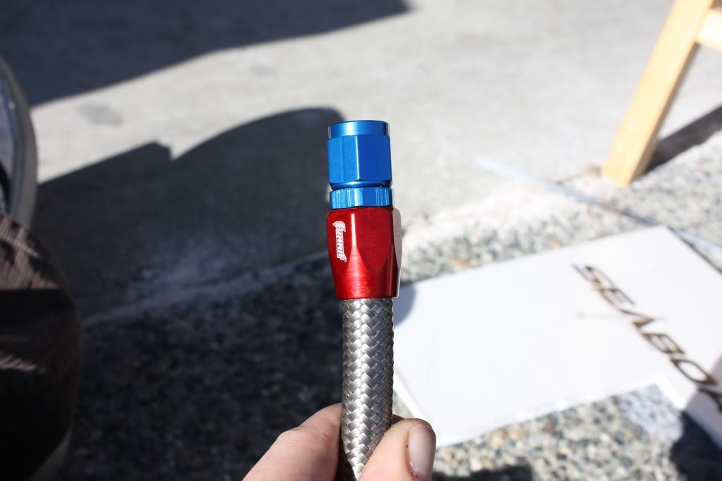
This process will be used for each fitting that connects to a line.
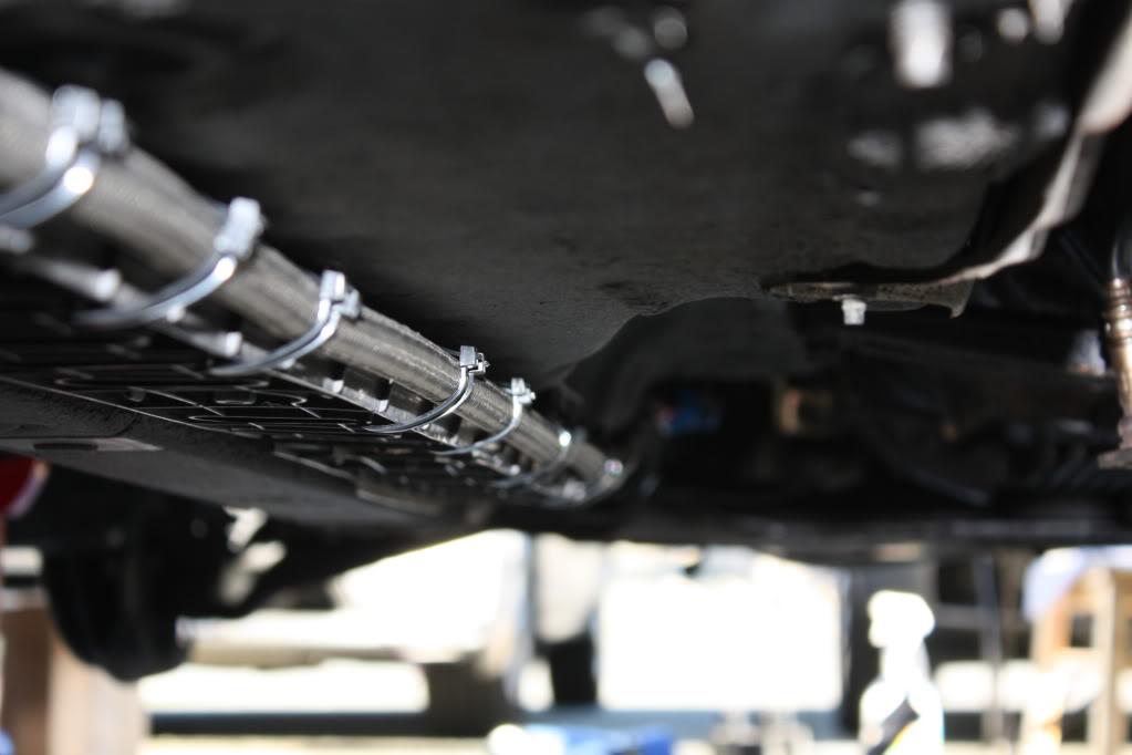
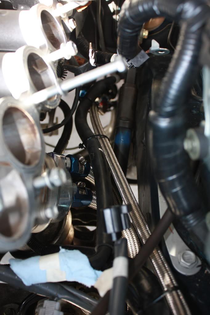
Alright, starting at the rear of the car at you bulk head fitting measure out the length of line you will need for your second feed. I used a piece of string that was fed along the intended routing path of the line, worked great.
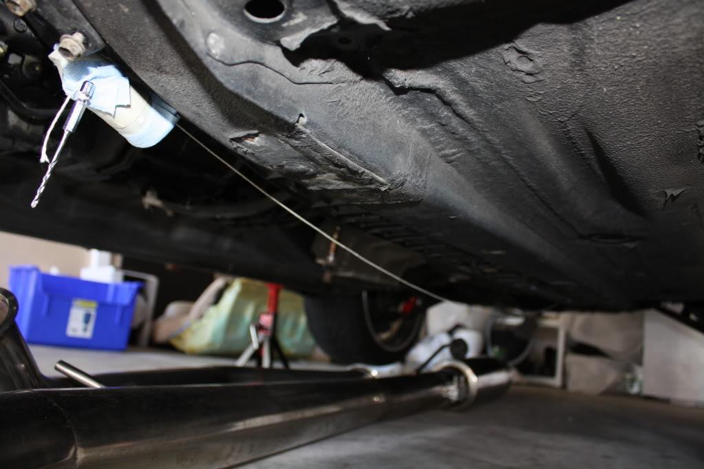
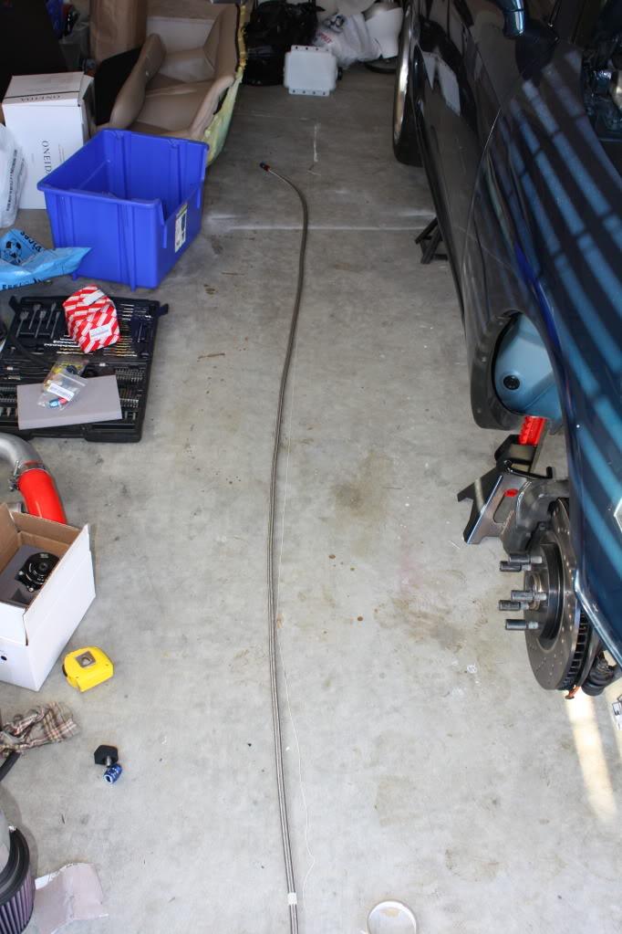
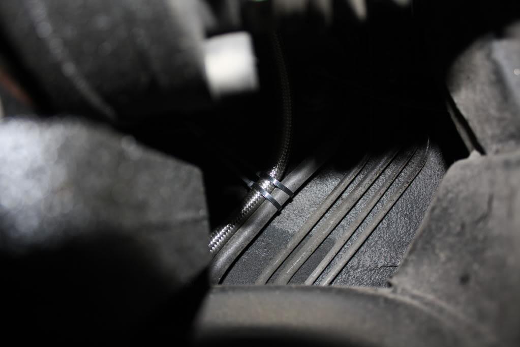
The route you take with the line will depend on you. I attempted to route it along the same path as the OEM feed line where possible. Meant a couple extra bends but worked out nice. Be mindful not to kink your line!
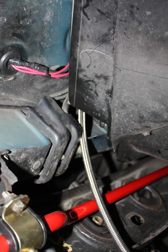
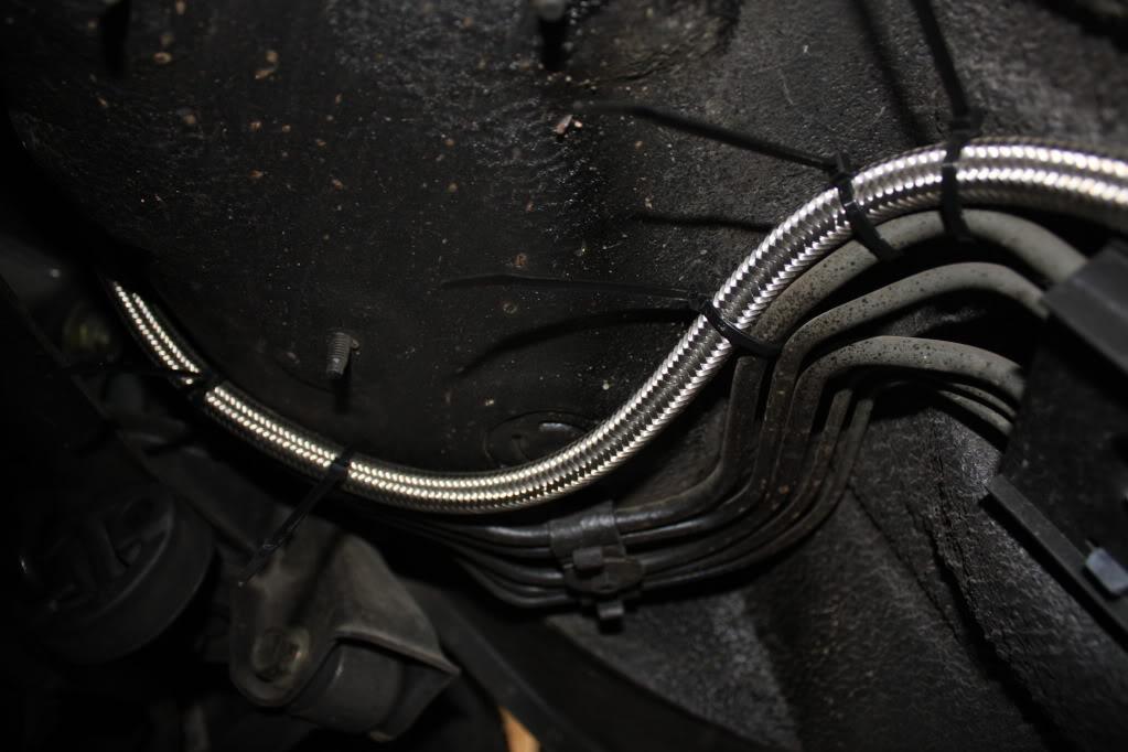
Ending directly where planned.
Note: I used zip ties to secure the line, like 100 of em. Optionally you can use a line holding bracket of some fashion and screw it into the under side of the car. I have no worries with this method it will be impossible for 100 zip ties to fail at once causing an issue with the line. That being said, I'll have to monitor them as you would anyway every year or so and replace as needed.
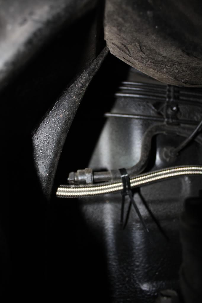
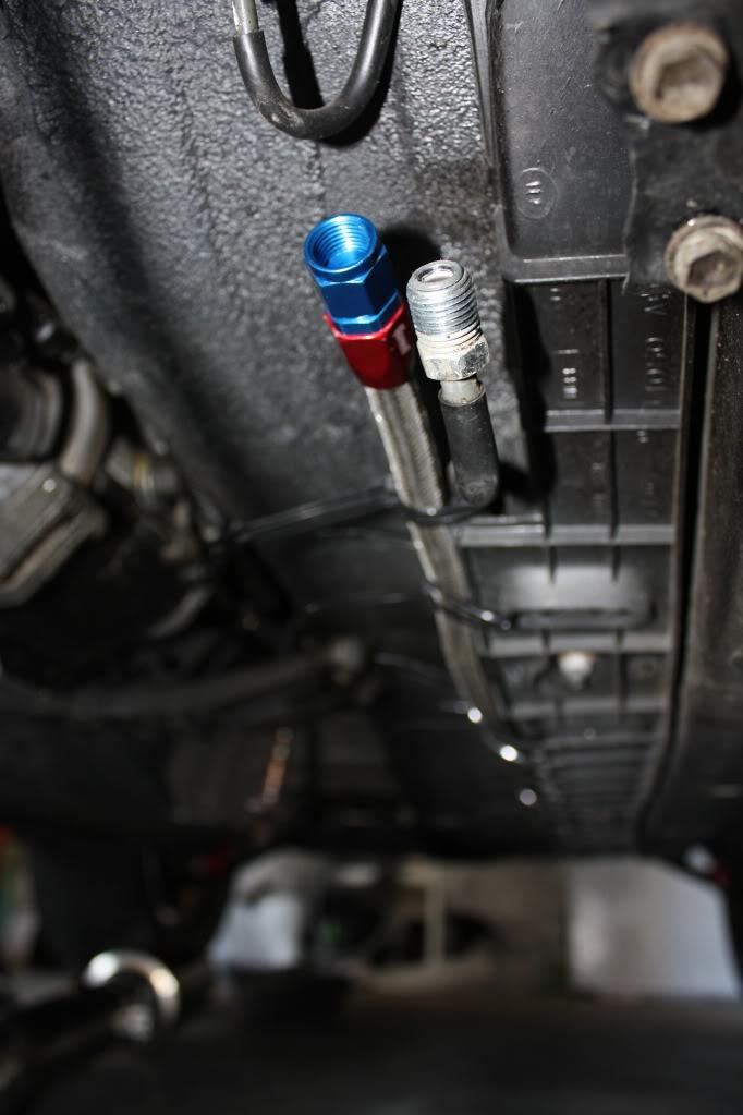
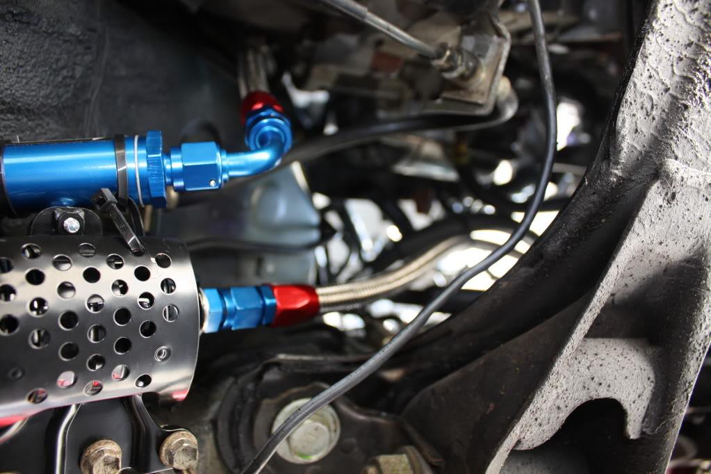
Now install the filters. The new Earls filter you purchased goes on your new feed line. The OEM filter goes where on the OEM line obviously. The key for the OEM filter is the engine side, you connect your adapter bolt you purchased like so. Note: There is an arrow showing the intended flow of the Earl's filter.
Clean up the zip ties so everything looks clean. The line should be very snug, but not crimped with no slack.
Re-install the rear heat shield once you are done this part.
Before you can run the rest of the lines you should get the lower runners installed, the injector bungs in, and fuel rail/injectors attached. This will allow for better routing and eliminate guessing as to proper line length. Also this is a good time to clean your runners out since they are off.
Prepare you fuel rail and injectors first. They push into the rail with a bit of pressure. Ensure the o-ring is on the injector to prevent leaks.
Silicone in the injector bungs that came with your injectors, otherwise they don't fit. High temp silicone is used for this. It is advisable to silicone the bungs just prior to installing the rail and injectors. This will push out the excess and allow for a cleaner install.
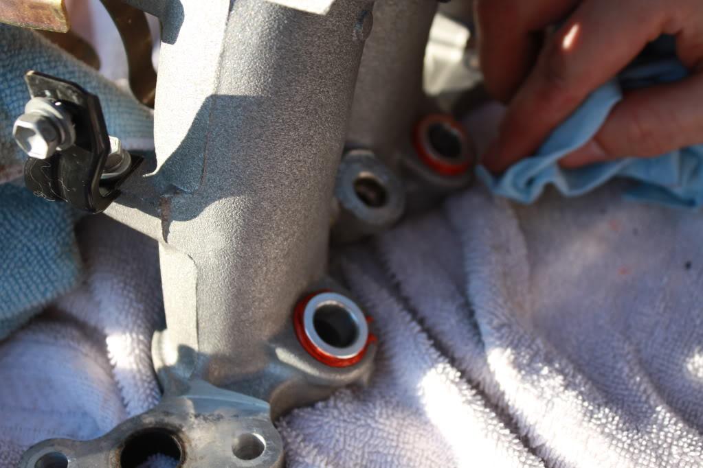
Ensure the inside is clear of silicone and debris.
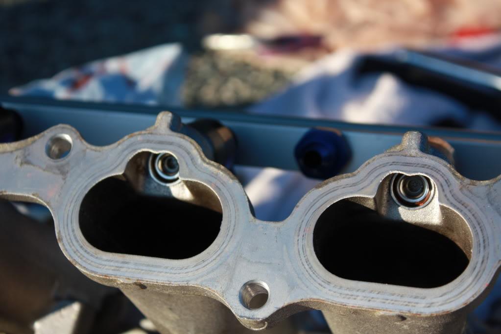
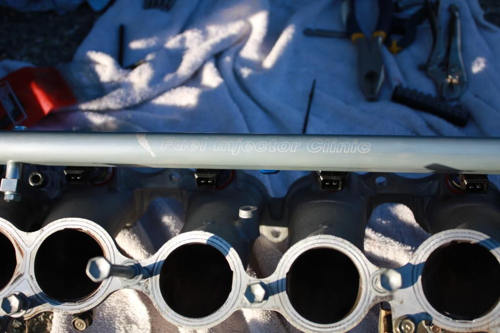
Install the gasket, then the runners and torque down as per the TSRM.
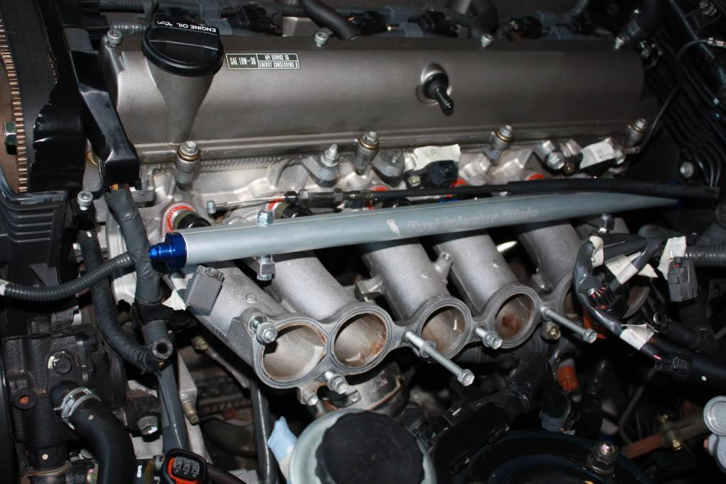
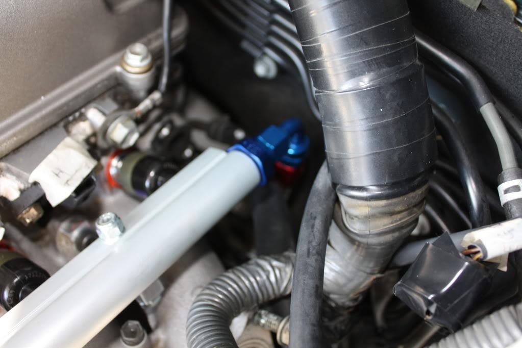
With the rail installed you can measure, cut, and install the feed lines from the filters.
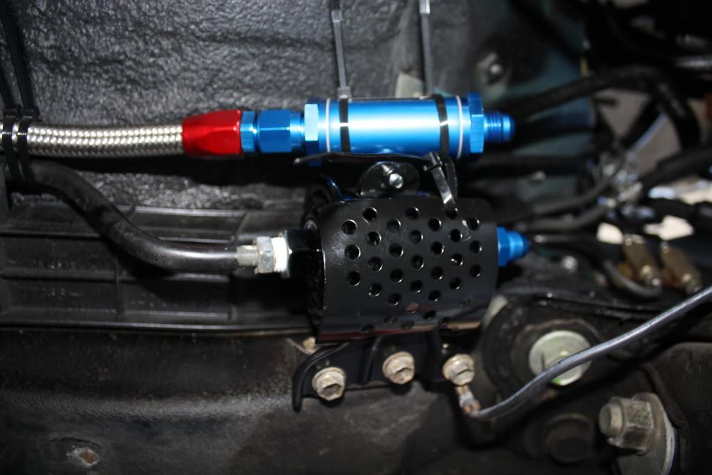
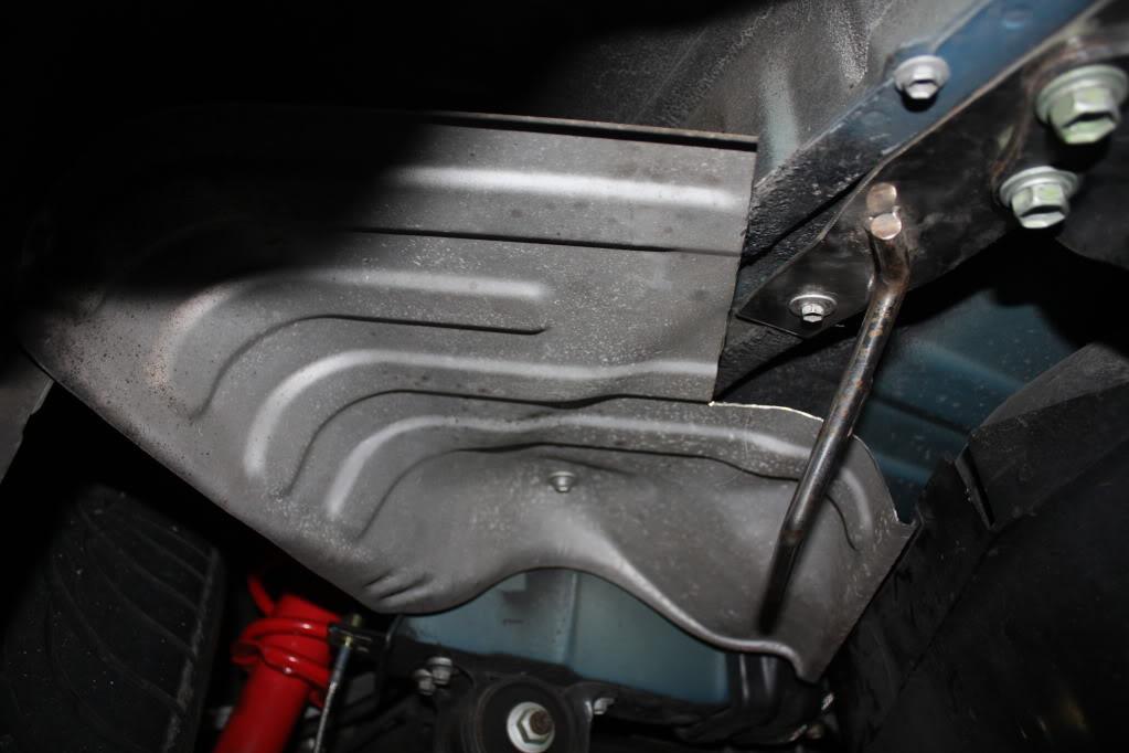
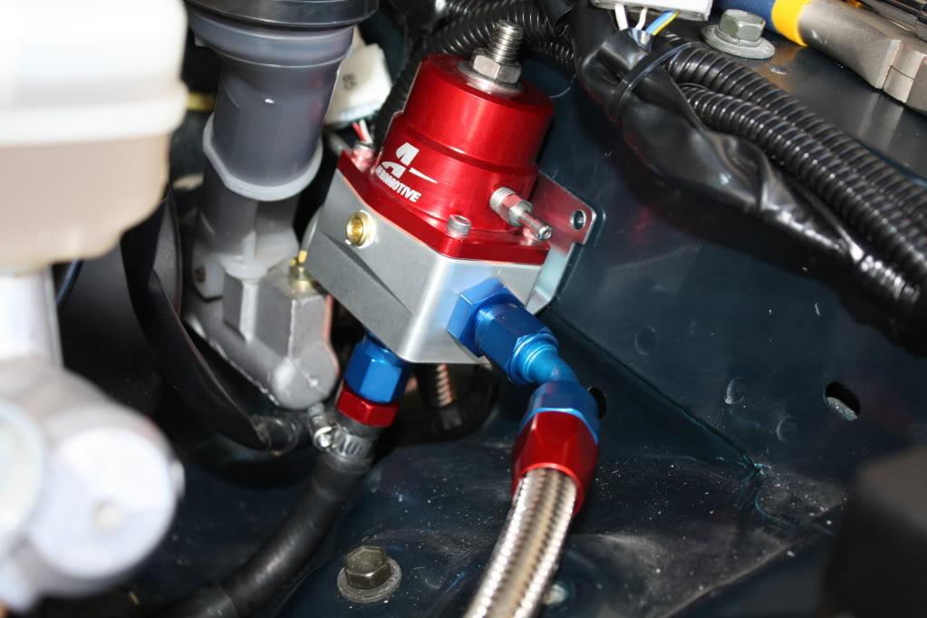
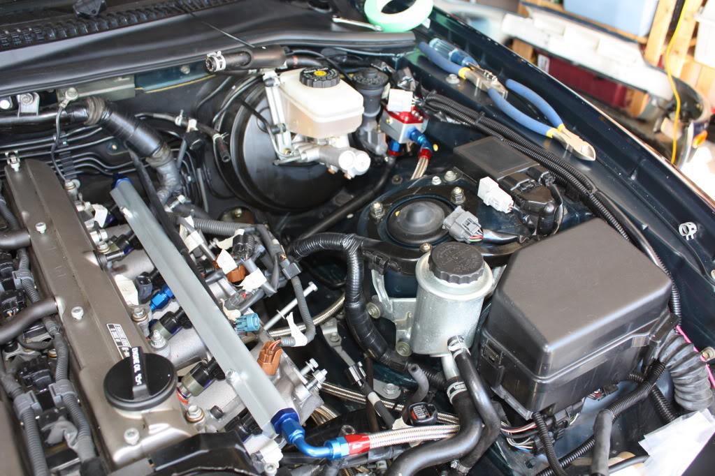
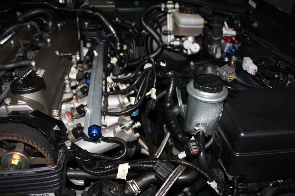
The next part deals with the return line and FPR. First determine a mounting location for your FPR. Since I removed my TRAC Pump I had a perfect hole open for it. In addition to that there are OEM mounting holes that can be utilized. Widening of the FPR bracket holes will be required for that. If you have a FPR bracket from PHR or MVP install as per their directions obviously.
You measure, cut, and install the return line from the center port of the fuel rail, and into either side of the FPR. You plug the other side port. The bottom port connects a twist tite hose fitting, which you connect your OEM return line to. When you are done it should look like this.
You are nearly finished! The next thing to deal with is the injector clips themselves which are supplied by FIC. Here is where labeling things will have come in very handy. Work you way along, clip by clip installing the new ones. The polarity doesn't matter, however I put them all the same, ie: red wire on the clip to the multi-colored wire on the OEM loom, black to the solid. I soldered the connections here. However post-write up and posting I've switched to connectors. Either way will work, I felt more comfortable with the connectors after the fact.
When you are done you will have six clips ready to go. You can take some extra time and clean up the wiring over here like I did. Most of it will be hidden by the upper chamber, but either way, looks better than the old stuff.
Congrats, you just finished installing your new fuel system. Now put everything back together, opposite to how it came off.
Ensure all your connections are tight, o-rings are used where needed, and teflon tape any required threads. AN fittings don't require any but if you want to put it on go nuts. Once you are ready to start the car I would prime the lines and rail by removing the EFI fuse so there is no spark. Check for leaks without engine load, and again with load at every connection point.
Other How-To's I've put together:
TRAC Pump and Actuator Removal