You must be logged in to rate content!
10 minute read
E39 DSP G.A.S. Crossover Install
Compliments of StereoInstaller1 @ r3vlimited.com
11-11-2013
Hey there!
Today, we will be doing a quick walkthrough on how to install the German Audio Specialties E39 DSP Passive Crossover Network, AKA the "PCN".
First, let me explain the purpose of this product: this PCN allows you to remove your factory amplifier and replace it with a normal 4 or 5 channel aftermarket car audio amplifier while retaining your factory speakers.
The goal of the PCN is simple, but multifold. The PCN allows replacement of the factory deck with an aftermarket "head unit" and/or allows far higher levels of performance for those who wish to retain the stock deck. In addition to those looking to improve performance, this is a cost effective option for those who simply wish to replace the stock amplifier due to failure.
Either way, our primary goal is to allow replacement of the factory amplifier.
However, a wonderful side benefit of this product is that it produces extraordinary sound quality, far surpassing the "expected" level of performance. We will get into the details of how and why this PCN produces such incredible sound using the original speakers at some point, but for now let us just say that this performance is especially impressive given the generally underwhelming performance of those same speakers when powered by the factory amplifier.
You can expect sound quality of a very high order when using this product, assuming two things: first, that your original speakers are in good condition and that this product was properly installed. As said above, the goal is a simple installation, but do not kid yourself, this installation requires skill and patience. If you have read this entire tutorial and are still convinced you will cause yourself grief, please contact us, as we have several installers willing to provide their talents professionally. The last thing we want is to hear of our hard work in designing, building and marketing this product being wasted sitting on a shelf!
OK, on to the install.
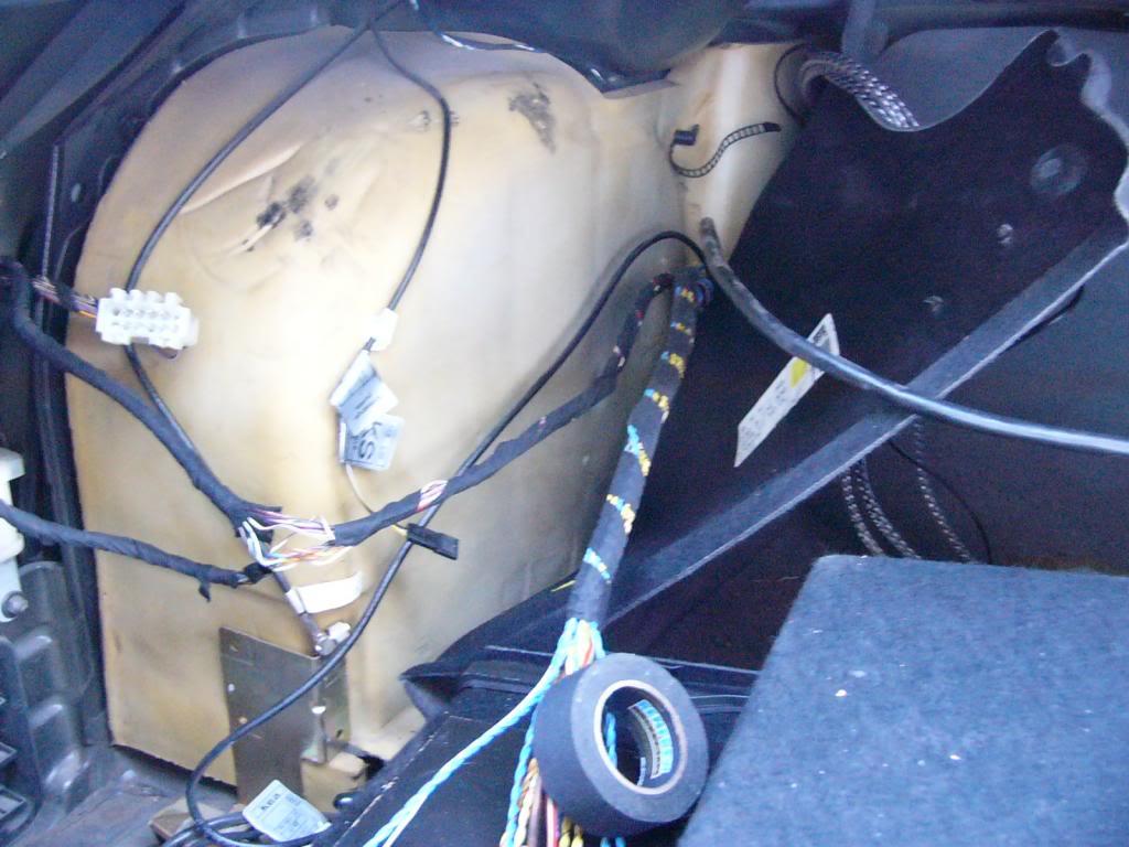
First, lets all hope you already know where the factory amp is, but just in case you don't, here it is with a partially hacked harness:
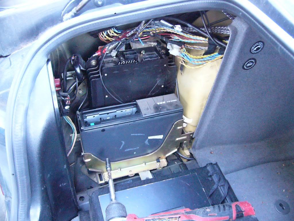
The first step is to remove the side panel of the trunk. You will be running wires and making connections in here, so just pull it. While you are there, go ahead and pull the stock amplifier and CD changer.
We got a lovely surprise when we pulled this one:
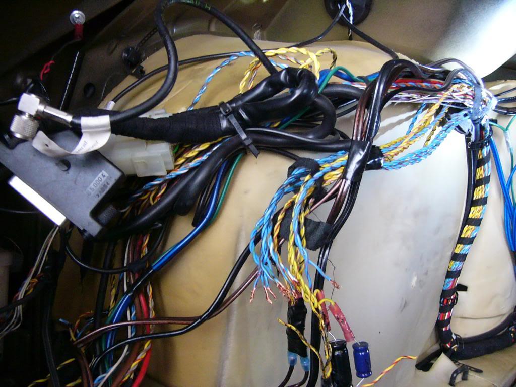
Yay, a big snarly mess of wire! These cars are almost always a nightmare when typical installers get hold of them, primarily because they are so challenging to interface with.
Here is what we found:
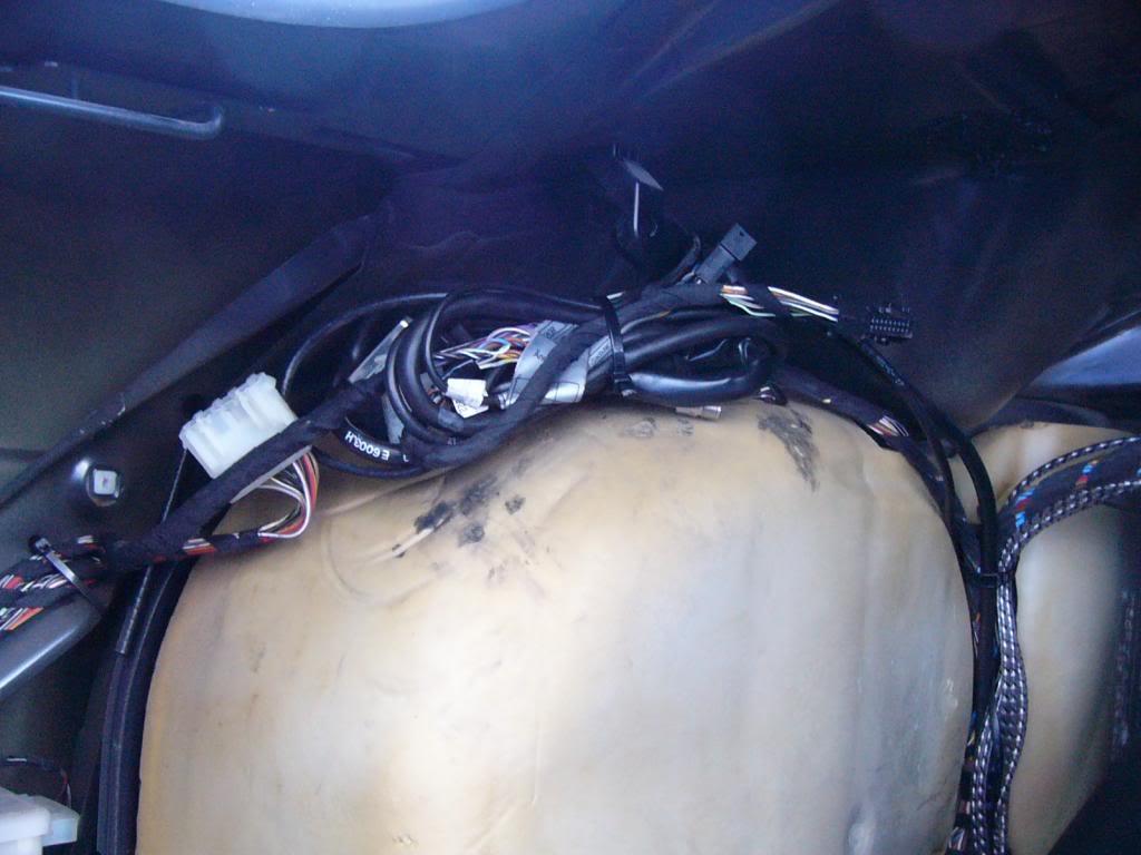
Oh yeah, we also removed the BMW cell phone, its brackets and all, then tied up the wiring. We only need the stock amplifier harness for our purposes here.
Tied up mess of cell wires:
So, the first thing you want to do is ascertain which wires you need. As stated earlier, you will be using 20 wires from the stock amplifier harness to connect the outputs of the PCN.
Lets talk about the harness of the PCN just for a second and how the color coding works.
When you look at your beautiful PCN, you will see there are two "banks" of wiring. One is Yellow and Black, the other is Blue and Black. Each of those banks terminate in a normal ATX plug and color-coded outputs.
Our color coding is intended to correlate precisely with the factory wiring scheme.
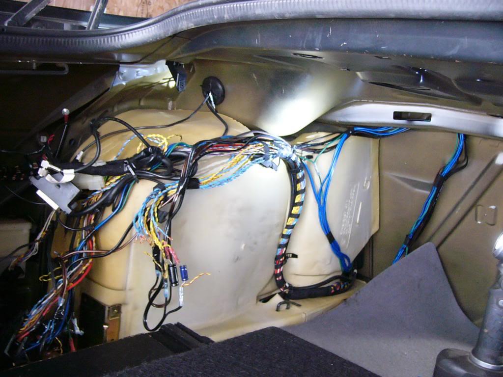
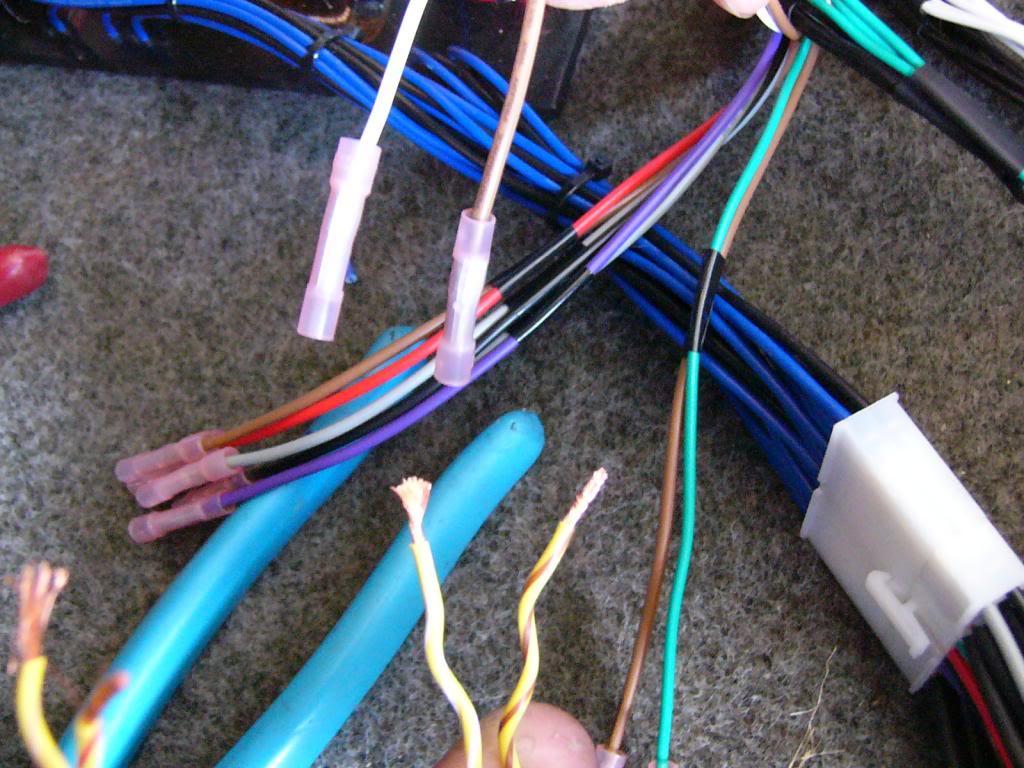
For example when you look at your factory harness, you will see it is primarily composed of twisted pairs of yellow and blue wires with color-coded stripes:
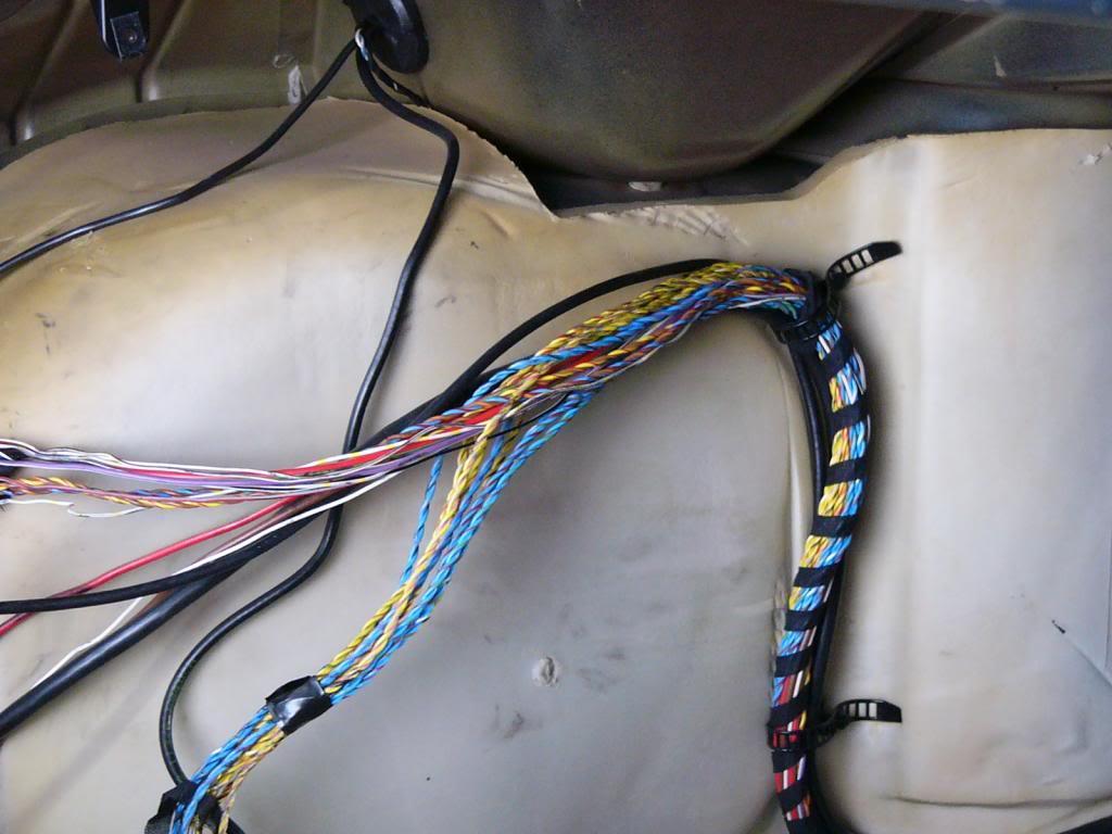
The 20 (10 per "bank) output wires are the same colors as the stripes used on the factory wires. You will see they are separated into pairs of wires intended to connect to a twisted pair on the amp harness.
For example: Yellow bank, red and brown pair of wires (Left Front Woofer) connects to yellow/red and yellow/brown of the factory harness. I hope this makes sense, once you understand the logic it is very easy to follow.
Don't overthink this! Blue bank, black and silver pair connect to blue/black and blue/silver, etc. Yes, it is a lot of wires, so take your time in getting an understanding for how it works, but in reality it is just as simple as 10 pairs of wires connect to the factory harness.
(E34PCN shown here)

So, now that part is starting to make sense, here is what you wanna do:
First, choose where you want to put your crossover. Yes, it can easily fit in the stock amplifier location. That particular part of the install is all up to the installer. Stray magnetic field can change the performance of the PCN, so we recommend not mounting it directly to the woofer, but aside from that, it is all up to you. In the examples shown, we will be installing a full GAS system including the PCN, one of our custom-fit chassis specific enclosures and our truly unique "Amp Racks".
Due to how we chose to install the PCN, we found it necessary to extend all 20 of the factory speaker wires. If you choose to install the PCN in place of the factory amplifier, extending the harness should not be necessary.
So what you want to do now is separate the speaker wires from the rest of the harness. As said above, there are 10 pairs. 5 of these pairs will be blue, 5 pairs yellow and all 20 will have stripes.
Here is how they are arranged in twisted pairs:
Yellow/? is left channel, Blue/? is right channel. We will show only the left channel, as the right channel wiring is identical.
Yellow/White and Yellow/Brown: Left Front Tweeter (+/-): White and Brown
Yellow/Green and Yellow/Brown: Left front Midrange (+/-): Green and Brown
Yellow/Red and Yellow/Brown: Left front Woofer (+/-): Red and Brown
Yellow/Black and Yellow/Gray: Left Rear Tweeter (+/-): Black and Gray
Yellow/Violet and Yellow/Gray: Left rear Woofer (+/-): Violet and Gray
I can only assume by now you see the logic of the coding. Brown stripes go to brown wires, blue bank goes to blue wires, etc. It is absolutely imperative that each of these wires are properly connected, we cannot stress this enough.
So, now you have decided where you are locating the crossover and have a solid understanding of both our color codes and the factory colors, lets proceed.
First thing is to test each speaker. Even though we know the codes. we still want to test each individual speaker so we know they will work as described.
To do this we HIGHLY recommend you disconnect whatever radio is in the dash before proceeding. You will use a normal "9V" battery in this procedure, so lets get to it.
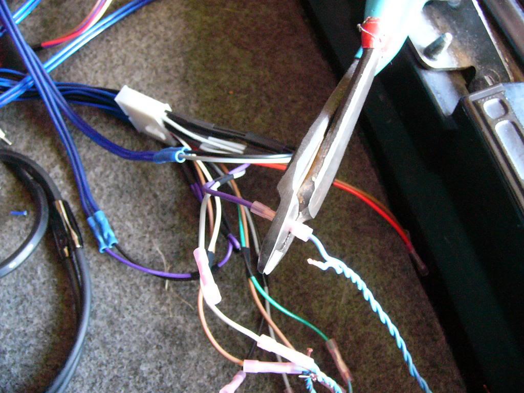
First, you already have the wires separated. You will now cut each pair from the factory harness, one pair at a time. When cutting, we recommend you leave at least a couple of inches of the wire available to re-connect the plug if needed.
(Quick note: as far as we are aware, factory amplifier plugs are not available for this chassis. The factory amplifier can be taken apart and the stock plugs utilized after removing them from the circuit boards. This is an advanced procedure so should you choose this option, please share your methods!)
So, at this point you should have 10 pairs of color coded wires loose from the harness. Go ahead and strip approximately 1/4" from each wire.
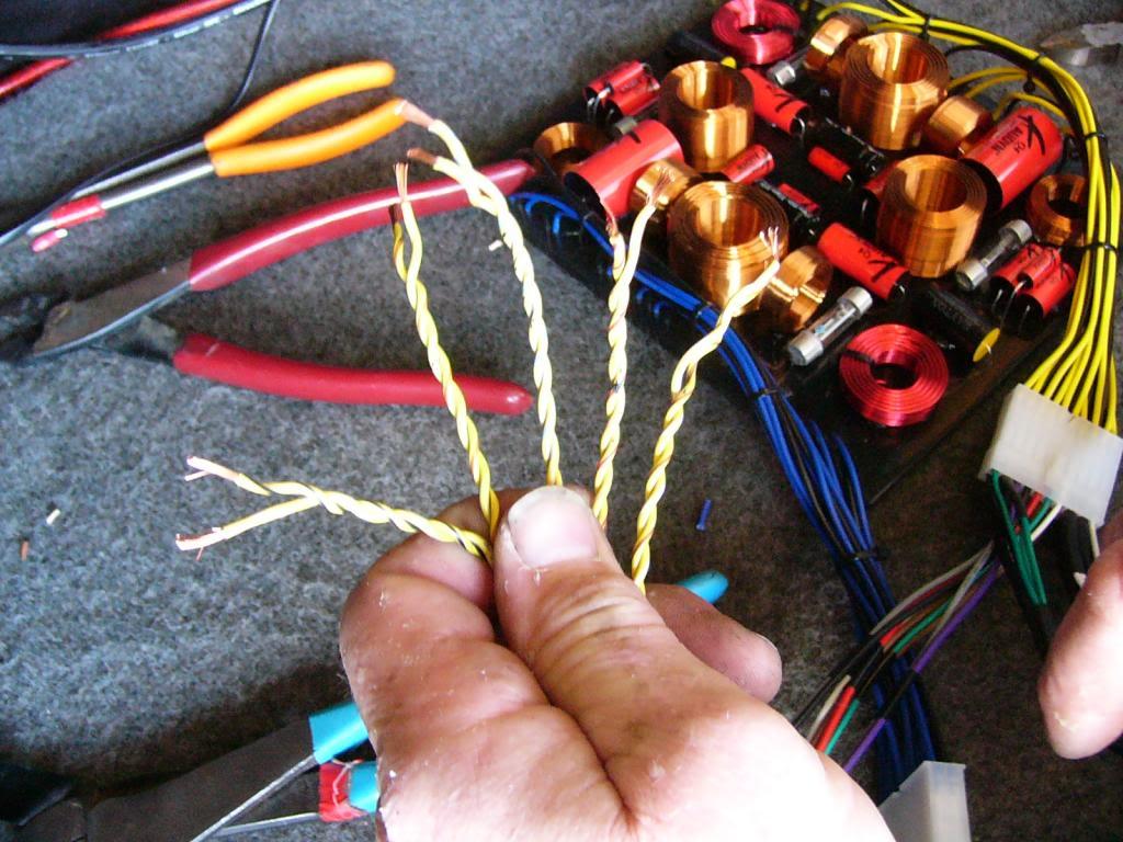
Now, take that 9V battery and quickly touch the two terminals of the battery to whatever twisted pair of wires you choose:
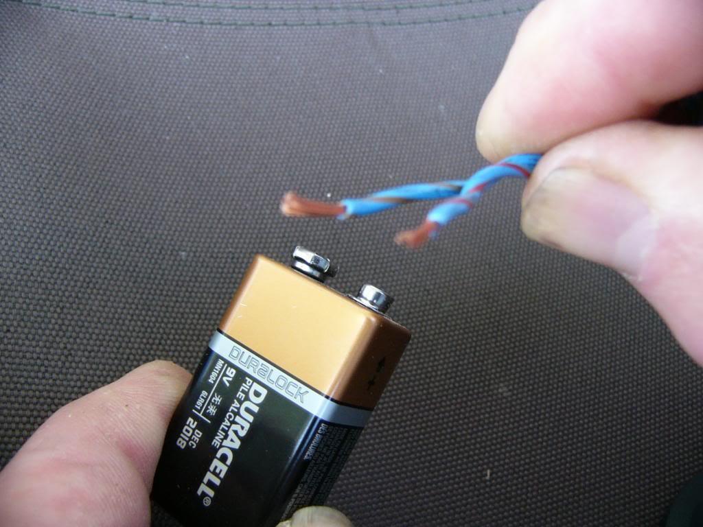
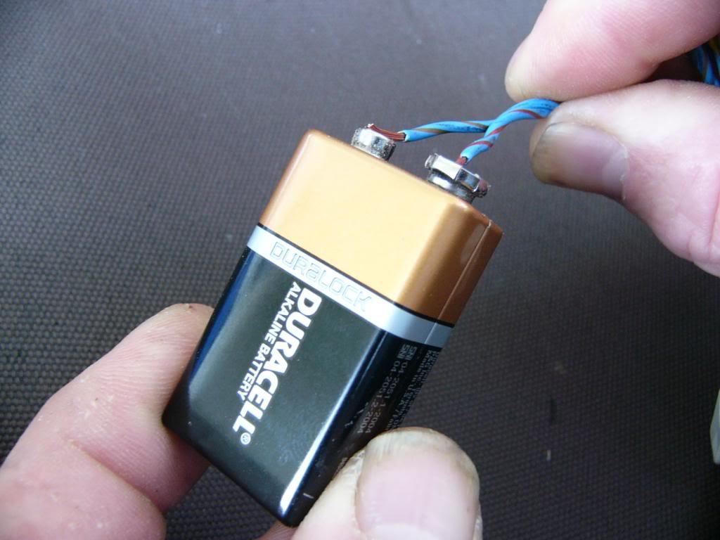
What you will hear from the speaker is a small "click". This testing procedure is a very common method used by thousands of installers every day, but it is not without risk. Do this testing at your own risk as you may (incredibly unlikely) blow up a speaker or blow up your radio (again, unlikely and I told you to remove it first!).
In an ideal world, you will have someone in the car that can pinpoint exactly which speaker "popped" just to double-check your wiring of the crossover.
So, that being said, lets make some connections!
Personally, I just grab the left (yellow bank) plug, remove it from the crossover and begin connecting.
So, here is that stock harness:
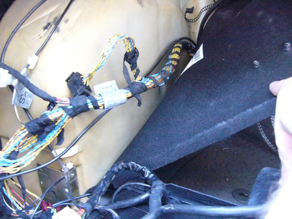
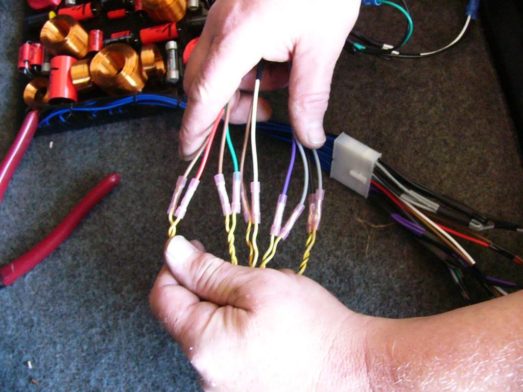
Here are the wires needed untangled and re-wrapped:
Now, lets strip and crimp all 20 wires:
So, lets check status again. You should at this point have 20 wires from your crossover connected to 10 speakers you have already individually tested.
Now, lets connect wires to go to your amplifier.
There are 8 remaining wires of the 28 total (ignore the jumper loops for now)
These 8 wires correlate to standard IEC aftermarket car audio color codes
Yellow Bank
Left Front: White and Black
Left Rear: Green and Black
Blue Bank
Right Front: Gray and Black
Right Rear: Purple and Black
Now you can connect those wires to your aftermarket amplifier and begin tuning!