You must be logged in to rate content!
7 minute read
DIY: E36 Electric Fan Wiring + On/Off Switch. Applicable to all accessories.
Compliments of HyphE36 @ bimmerfest.com
6-19-2009
This is a guide to wiring an aftermarket accessory.
In this particular case it is for an electric fan, which is more than likely the most common use. The fan is controlled by a simple On/Off switch placed in the cockpit. Instruction for everything is included.
Parts Needed:
1 Relay (common 5 pin 12VDC relay).
1 In-line Fuse.
16-20' length of correctly sized wire (go by what the accessory is wired with).
~15 (accounting for mistakes) Disconnects for wiring (for easy and quick taking off from relay and other sources).
~5 spade or ring terminals for grounds.
~a couple of butt connectors, for the in-line fuse and a possible mishap in wiring.
Tools Needed:
Wire strippers/cutters/crimpers
Electrical Tape
Scissors
The Process:
If you haven't wired anything before you may be asking what a relay is, just as I had.
To get familiar with a relay I watched the following video. If you are already acquainted with the wiring of a relay and how it works feel free to move on. I will go into detail on what to hook up to where so don't fret if you aren't sure what you are dealing with yet.
Before getting to actual work you should start by disconnecting the battery.
The attachments below will be a visual aid. They will be Figures 1-15, from left to right and top to bottom, like a book or any literature reads.
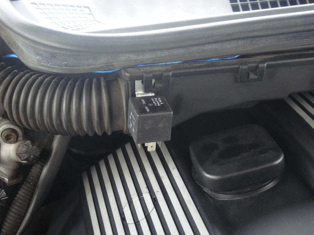
Start by finding where you want to mount your relay. Figure 1 shows where I chose to put mine.
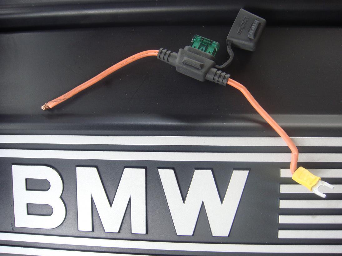
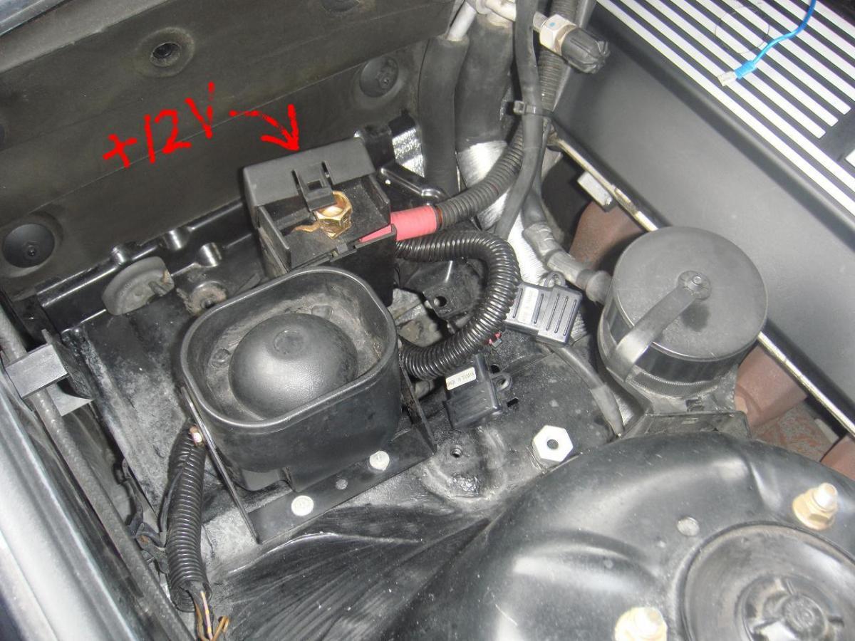
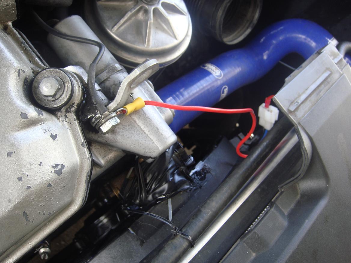
Get your inline fuse and connect a spade terminal to one end, and put that on the +12V source in the engine bay. Figure 2 shows the in line fuse with the spade connector, and figure 3 shows the +12V source.
Now measure the lengths of wire you will need for these paths in the circuitry (Keep in mind where you want the wire to be when you are finished and cleaning up. you may need to give yourself lots of slack on some of the wires depending on how you run the wire);
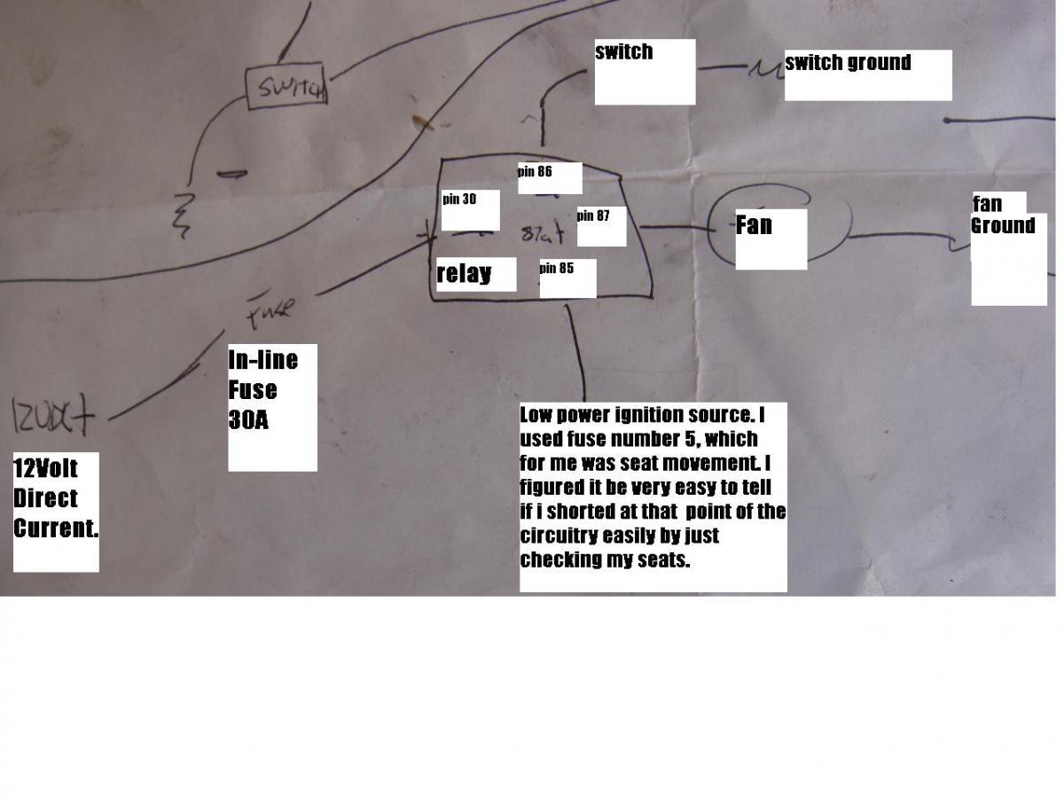
From the relay (pin30) to the In-line fuse off the +12V power source.
From the relay (pin86) to the Positive lead on the switch in your cockpit.
From the relay (pin87) to the Positive lead on the fan/accessory.
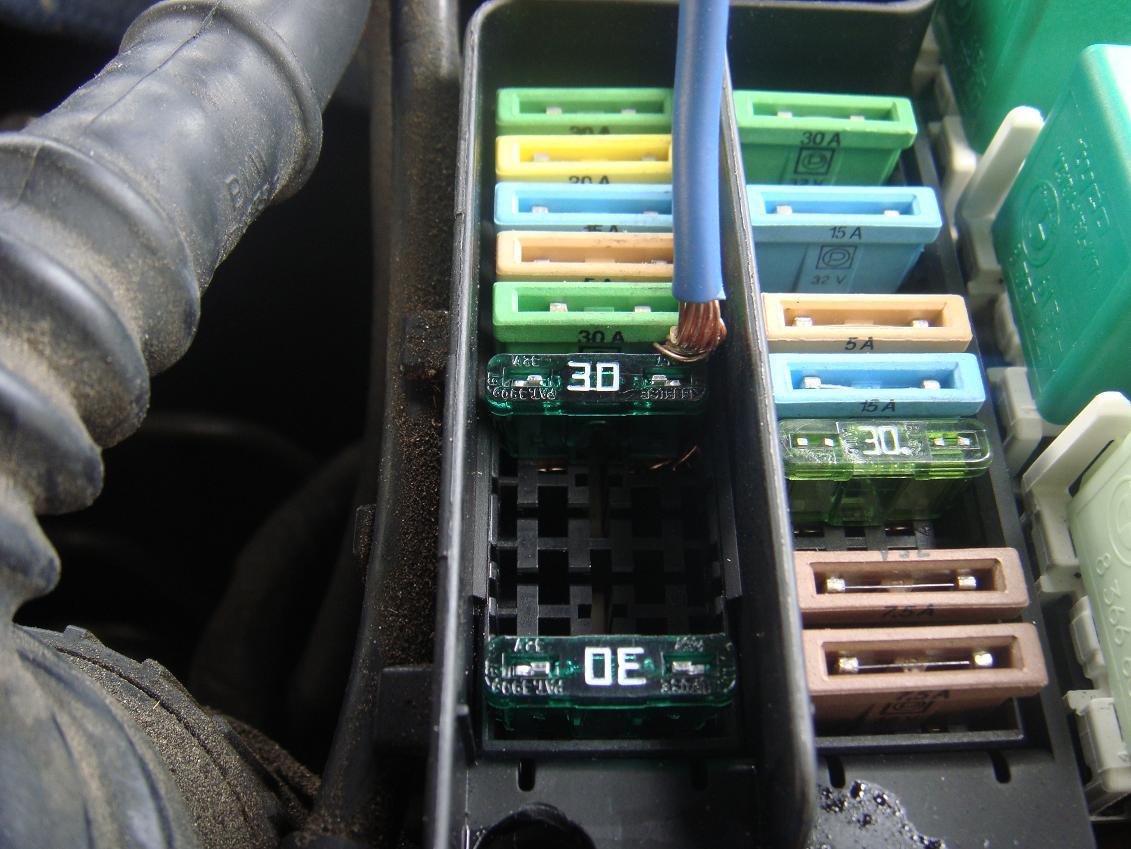
From the relay (pin85) to a Low Voltage Ignition source. For my 1995 325is I used Fuse #5. (shown in Figure 14)
Pin87a is ignored in this application.
One end of these should be fitted with the proper fitment to your relay, not all relays are like mine, though the vast majority are.
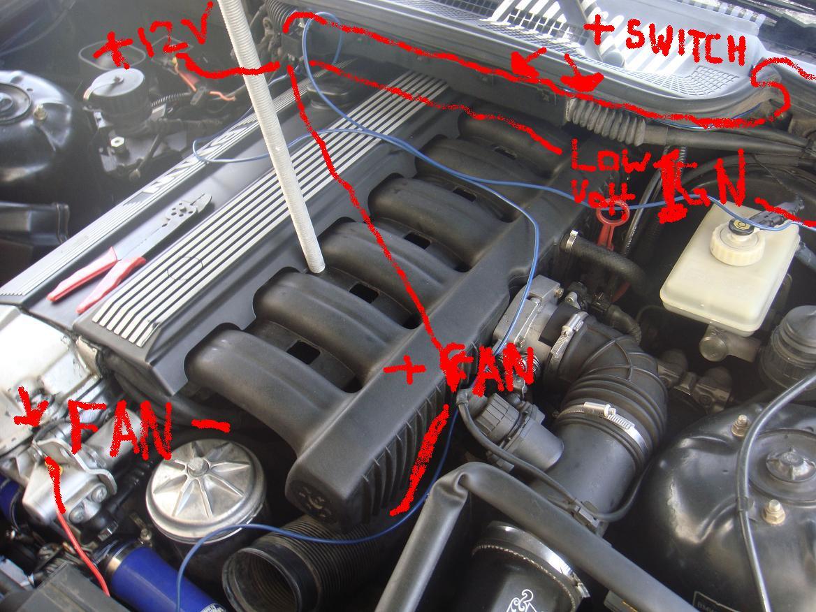
Figure 4 shows the wires running from the relay to their various functions. I have horrible photo skills so please dumb down your analysis, its very simple.
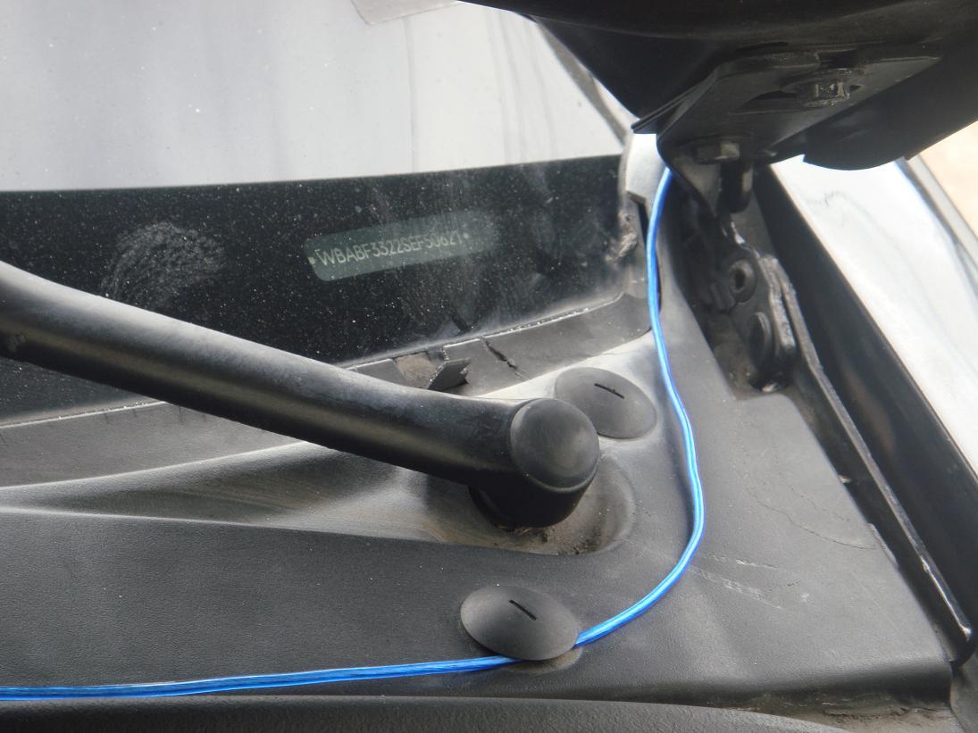
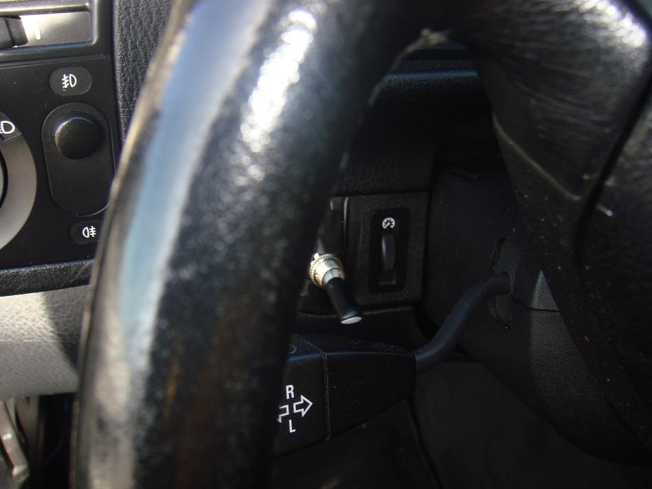
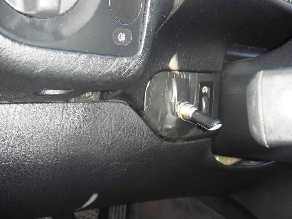
I didn't have the tools or means to get through my firewall, especially with a broken hand, so to get the wire from the engine bay to the cockpit I just did it like Figure 5 and 6 show. You can see my switch in Figure 7. Getting the wire to switch is a breeze, just remove the lower dash panel under the steering wheel with three screws, then the dimmer switch panel is where i placed my switch, not very clean yet, but effective, figure 8 shows another view.
Wiring the switch is straight forward. Take that lead from relay pin 86, and connect it to the Positive lead on the switch. Take another piece of wire with a spade connector on it and find the nearest ground possible, connect that to the switches Negative Lead to ground the switch and close the circuit. I'm sorry I don't have pics of this, I did before my hand broke and didn't want to do it over again. its easier than all the rest though, you're doing great! 
Next find a ground near your fan or accessories Negative lead and connect the two using wire and spade or ring terminals. Figure 15.
Figure 9 here is a little schematic that may help with the wiring in case you are having any problems so far.
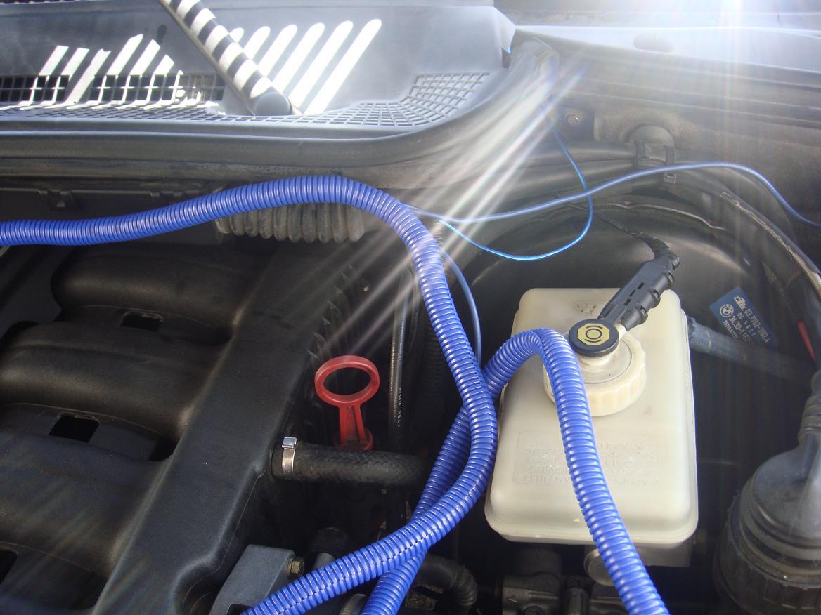
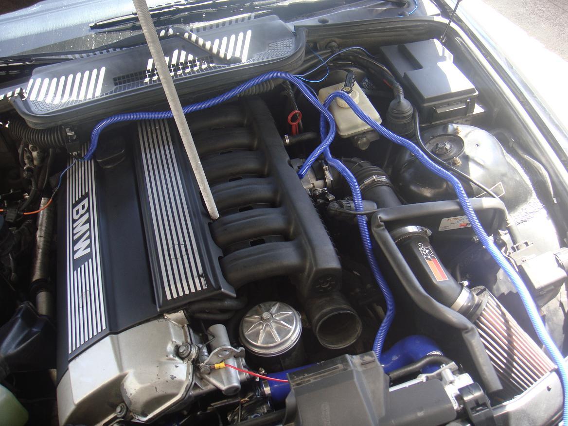
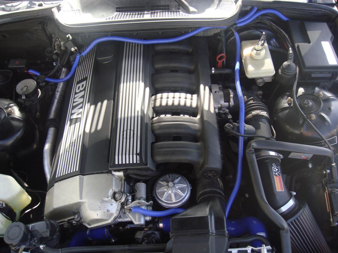
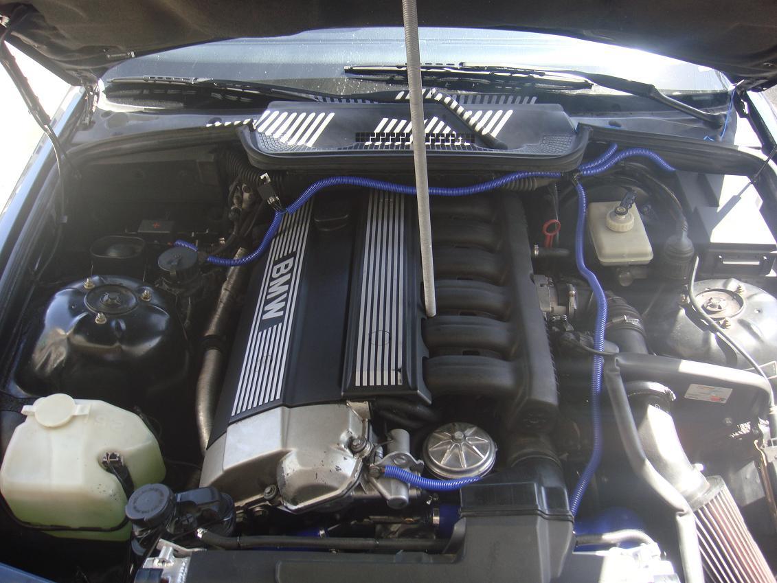
Make sure all the connections are good and secure. Now you can start to make it look better, if you want. Figures 10 and 11 show a little beautification going on over my wiring and Figures 12 and 13 show the finished result. Although, I am going to polish it up even more tomorrow 
Reconnect your battery, and go turn on the car. Flip the switch and see if its all good  If its not all good, then check every part of your wiring from each pin on the relay, and make sure that the wires are connected to the right pins. as explained in figure 9 and in the wire cutting section.
Clean up your tools and go for a nice ride with your new electric fan or what ever accessory you decided to install.