You must be logged in to rate content!
24 minute read
DICE with XM as Aux input DIY for cars with DSP for E39
Compliments of bmwm3coupe @ www.bimmerfest.com
DICE iPod and XM Integration Install in a 2000 BMW 540i with Coax DSP
April 14, 2007
William Quiles
Introduction:
I have Sirius on my Charger for well over a year now and XM radio on my old 1995 E34 525iI (via the cassette adapter), so then I sold the 525i and got this used 2000 540i about 3 weeks ago, I knew I was going to have find a way to get XM again, and this time I wanted to try to get it directly into the stereo, without any cassette or FM modulator crap. At least that was the initial goal.
Although I am not about to do a full blown Stereo Upgrade like I did on my old 2002 BMW M3 Coupe link , I started the same way – read/research everything I could point a browser window to!. As it turned out my own brother who has a 2001 E39 530i with DSP was my biggest helper – big kudos to my brother!
He had some much of the early research since he had the “difficult” to deal with DSP system. He did the iPod integration using the Dison kit, which seems to be no longer available. However, in his research my brother found another guy who had figured out how to deal with the “DSP problem”. In fact, dealing with the DSP problem is very easy – you only need one single box/adapter, which is simply an Analog to Digital Converter sold by Radio Shack. That’s it. No biggie. In fact, as you will see in the pictorial install, anyone with basic wiring/soldering skills can do the same job I just did.
You can find plain vanilla auxiliary adapters from Blitzsafe and Soundgate (which is all you need just to feed your Sirious/XM as an aux. signal into the CD Changer port), but if you truly want iPod integration, the DICE system is hard to beat. My initial goal was just for the XM radio, but the DICE kit was not that much more than the plain Aux adapter, and the DICE had the built-in auxiliary adapter plus the ability to digitally adjust the volume/level on the aux input via the main stereo controls – this flexibility was the final straw in the decision to use the DICE kit.
I am doing this install in two parts, first with just the iPod and then adding the XM radio. I hope this will be helpful.
AS USUAL, THIS INFO IS PROVIDED WITHOUT ANY GUARRENTEE! THIS IS WHAT I DID & WHAT I HAVE FOUND - USE THIS INFO AT YOUR OWN RISK - I WILL NOT BE RESPONSIBLE IN ANY WAY, SHAPE FOR FORM FOR WHAT YOU DO WITH THIS INFO.
YOU ARE FREE TO SHARE/COPY THIS INFORMATION AS LONG AS IT IS SHARED/COPIED IN ITS COMPLETE, UNEDITED FORM, AND AS LONG AS IT IS FREELY AVAILABLE WITH NO MONETARY EXCHANGE REQUIRED.
Part 1: Basic DICE install and DSP ADC for the iPod
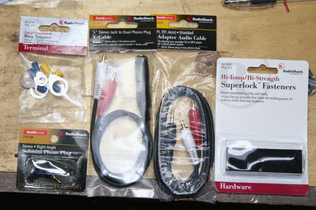
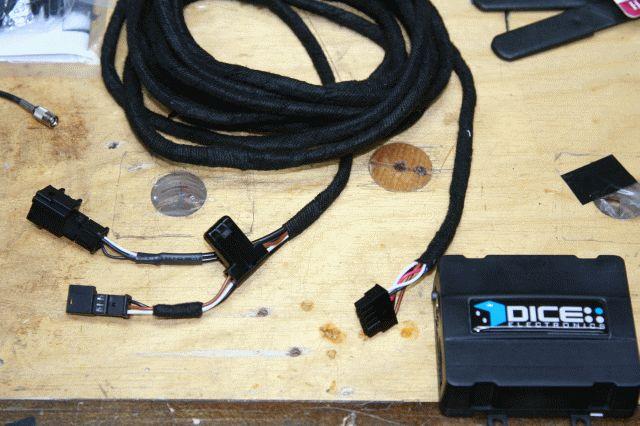
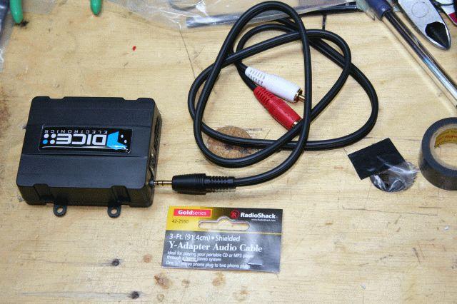
The basic problem with the Coax DSP system is that from the CD changer the audio goes to the amplifier as a PCM (digital signal). Most other stereos use single-ended or differential analog signals, so adding/interfacing stuff is relatively easy. For my system, all we need is a box that will convert the Analog signals coming from the iPod, or XM radio, or any other auxiliary input, back to the PCM signal that the amplifier is expecting. That’s all there is to it. Here are the actual components for this install:
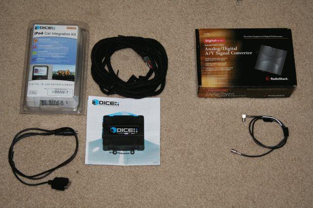
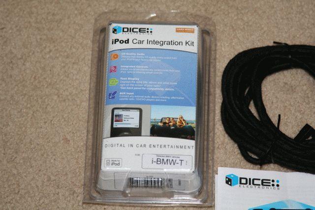
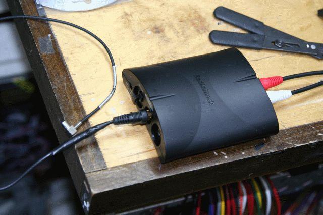
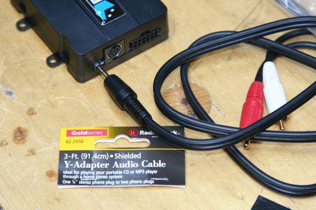
Here is a close-up of the DICE KIT:
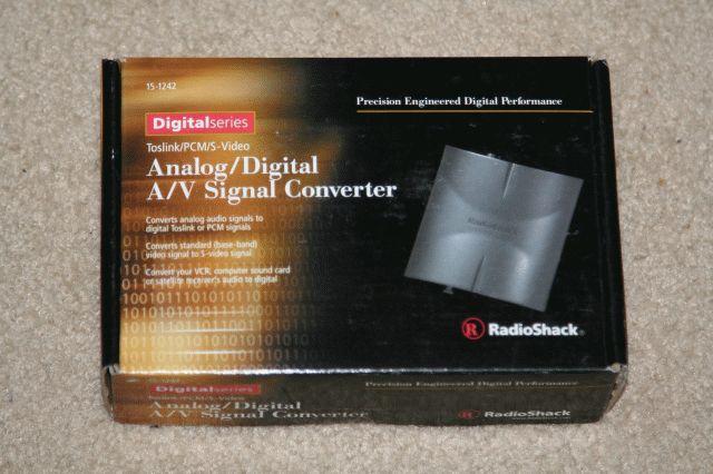
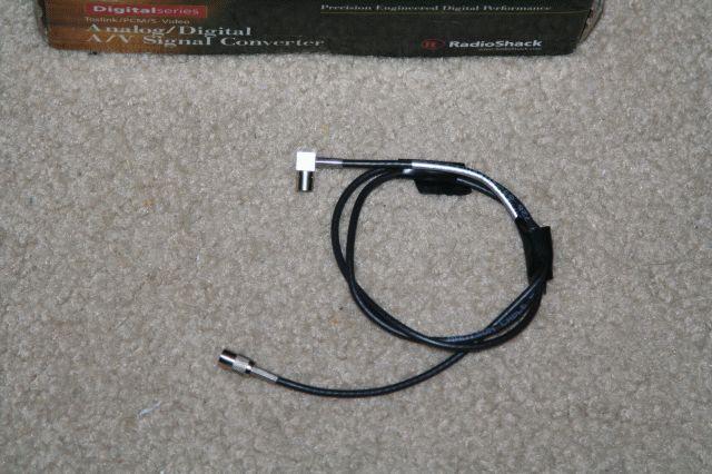
Here is a close-up of the “magic” box for the DSP “problem”:
And here is a close-up of the actual “problematic” coax digital cable:
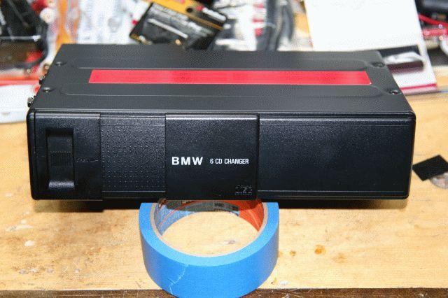
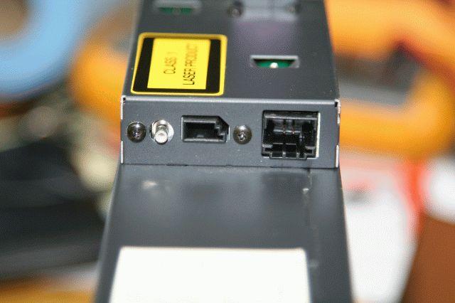
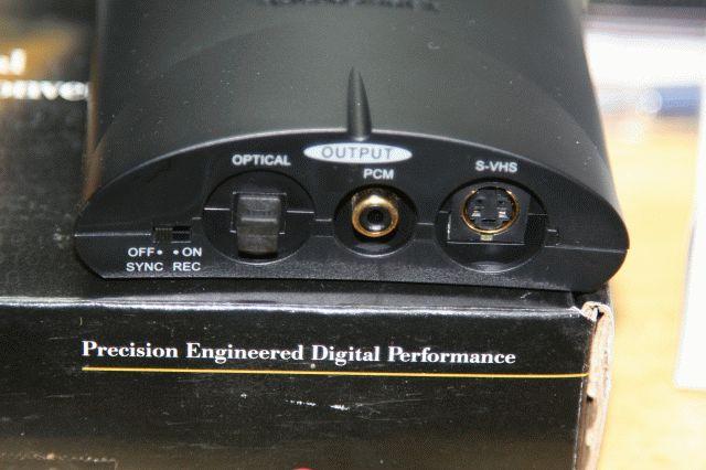
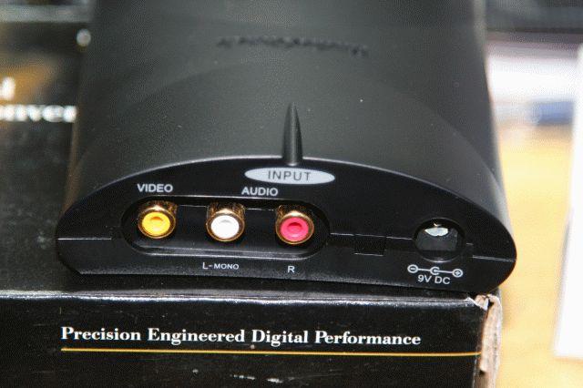
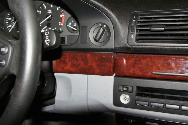
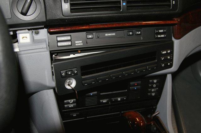
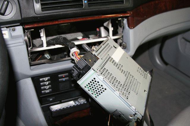
Here is the front of the CD Changer that I am removing (do you want to buy it “cheap”?):
Here is the back of the CD Changer:
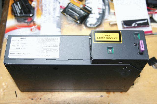
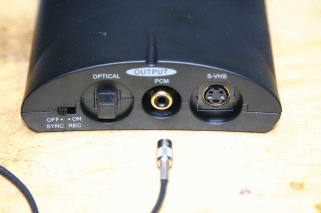
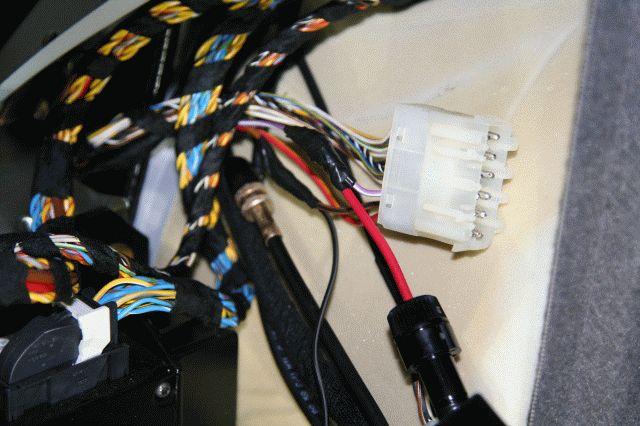
note here on the left side of the picture the coax digital output:
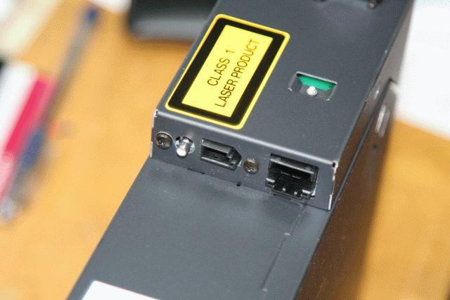
In the photos above, the small 3-pin connector in the middle is also “key” to the whole thing – this is battery, ground, and the I-bus control/data signal that communicates with the stereo system. This is the “data” port that adapters such as Blitzsafe, Soundgate, and DICE use to “trick/fool” the stereo into thinking that there is a CD changer connecter to the stereo – pretty cool, isn’t?
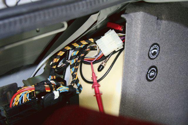
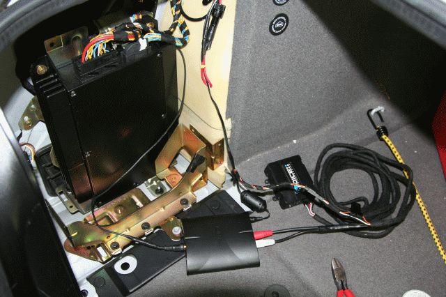
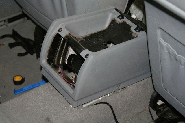
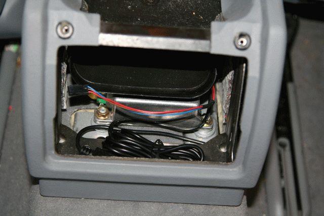
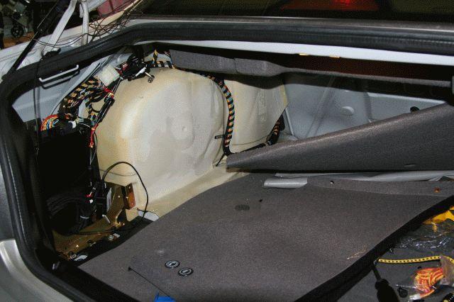
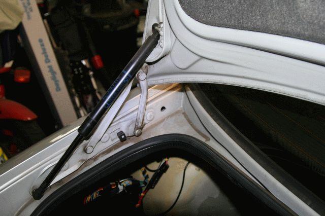
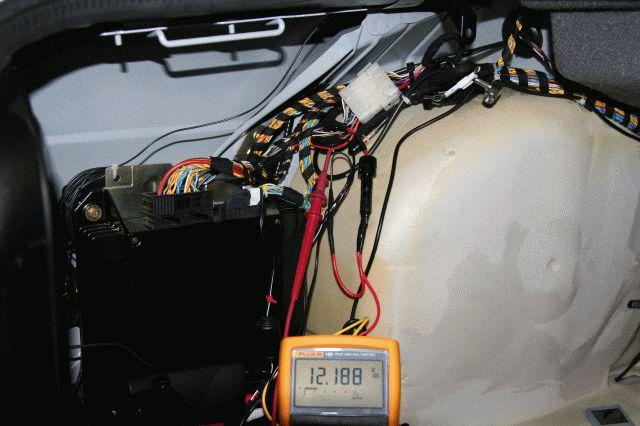
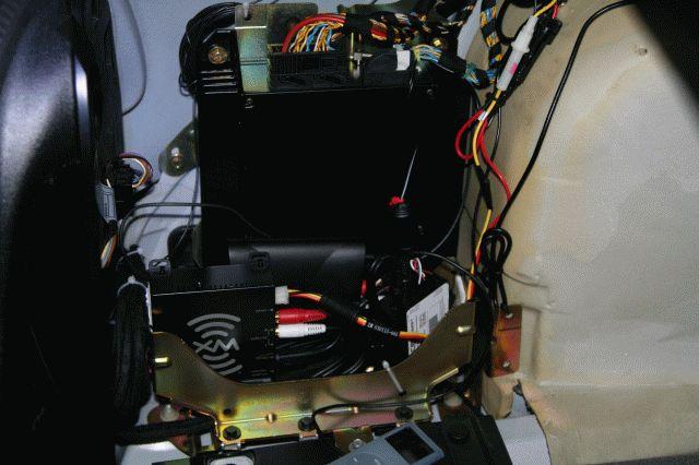
OK, so where is exactly all of this junk goes? Well, in the trunk!:
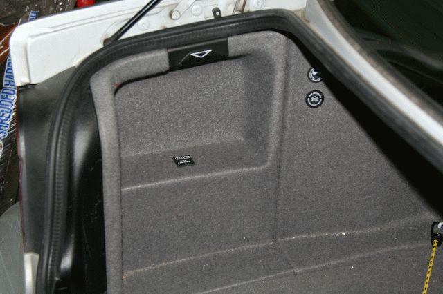
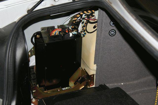
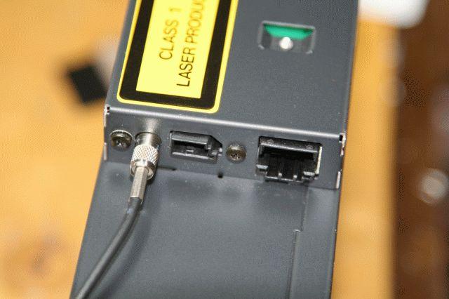
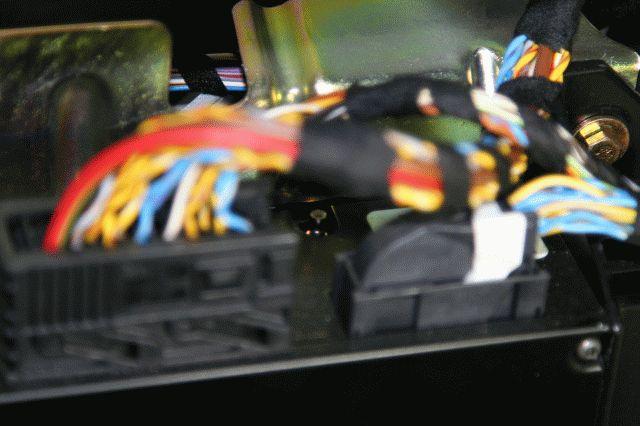
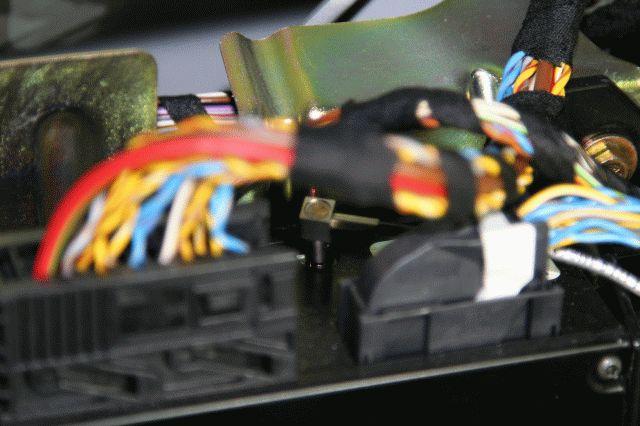
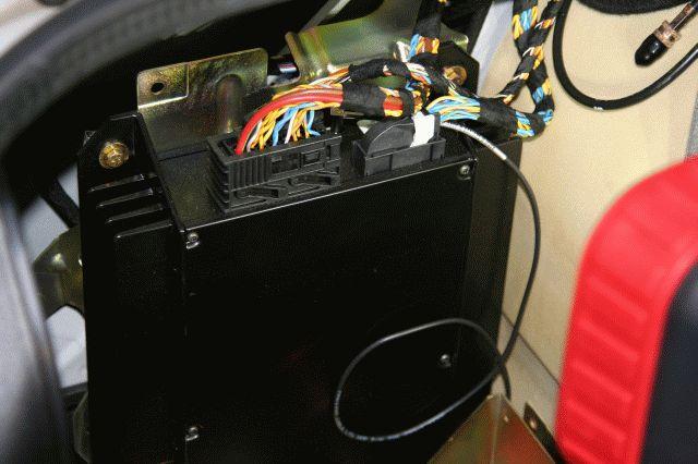
That big, black piece of metal is the DSP amplifier. Note in these to back-to-back photos where the coax Digital cable goes into the amplifier:
EDIT: Note that some companies do sell a "DSP Adapter/Module" that takes care of the work I am doing here by hand by using the raw piece from Radio Shack. It if of course more money ($100-150 for the DSP adapter), but it does make for a very easy install since all cables are pre-made. I decided to build my own, just like my brother did, which is what I am showing here.
OK, lets get back to the work bench. Here is the Analog to Digital Converter (ADC) from Radio Shack. My understanding is that this piece might be discontinued now, but you can still find them on Ebay from time to time.

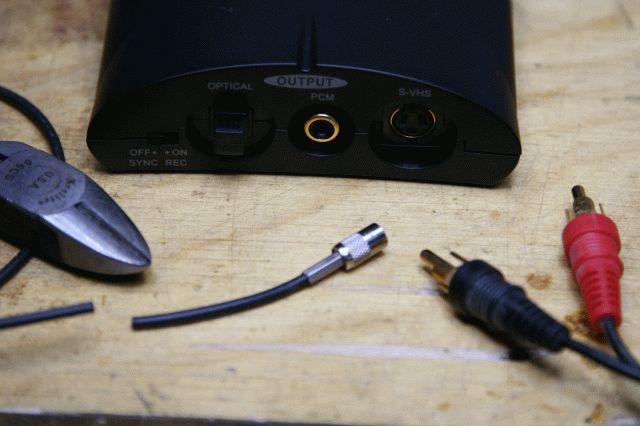
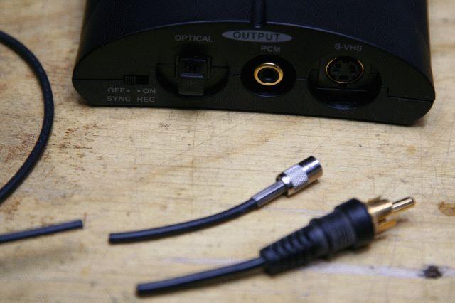
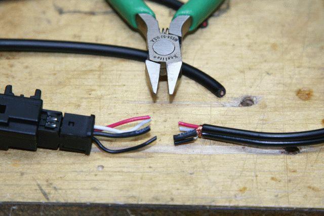
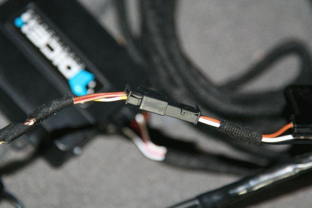
So the first problem is that the coax digital cable and the digital output of the ADC don’t work well together, mechanically speaking:
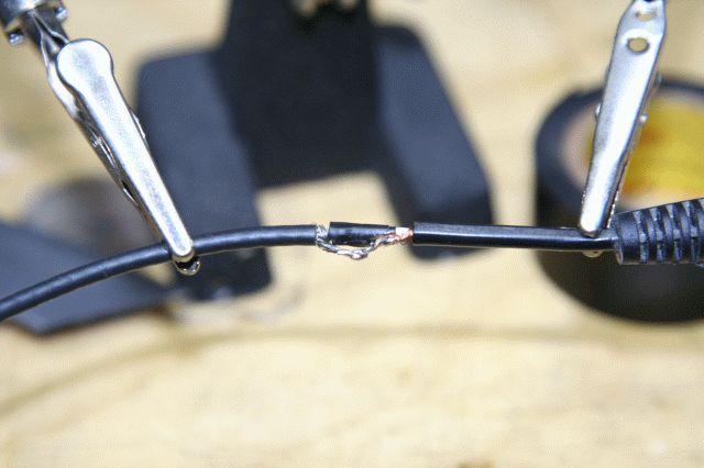
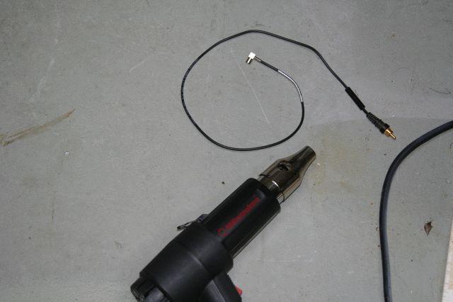
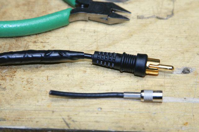
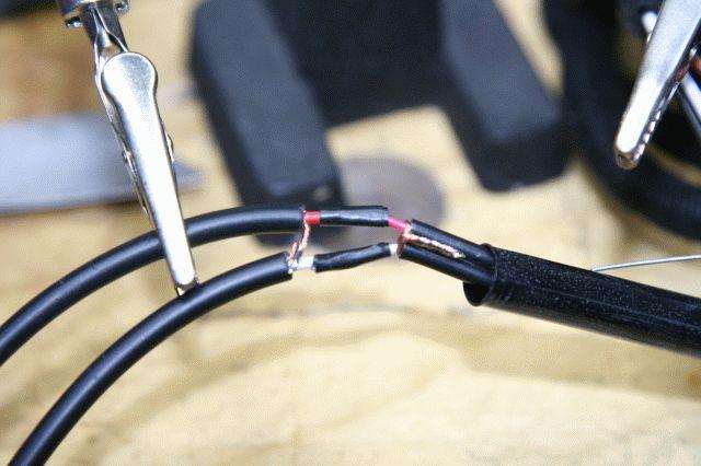
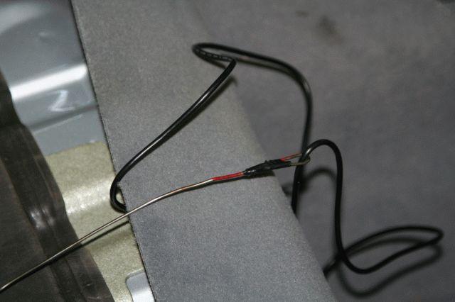
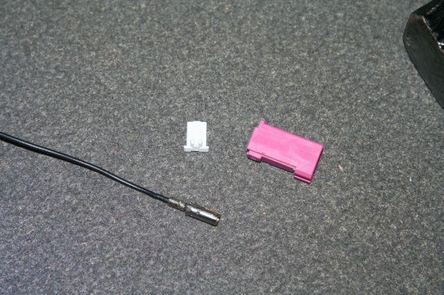
So we have to cut the straight end of the coax cable, and solder an RCA plug in its place:
As it was found by the original person who discovered the ADC, although the unit claims to need 9Volts DC, it actually works from 12Volts DC, which is what our cars generate. This is the loaded voltage at the input of the ADC, so we will be powering the ADC directly from our car’s power grid (with a fuse, of course! – more on that shortly):
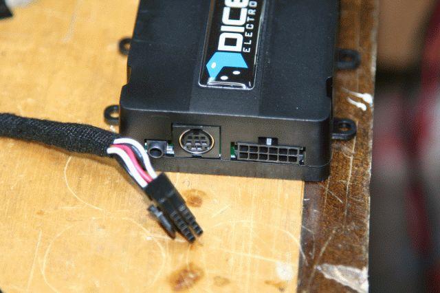
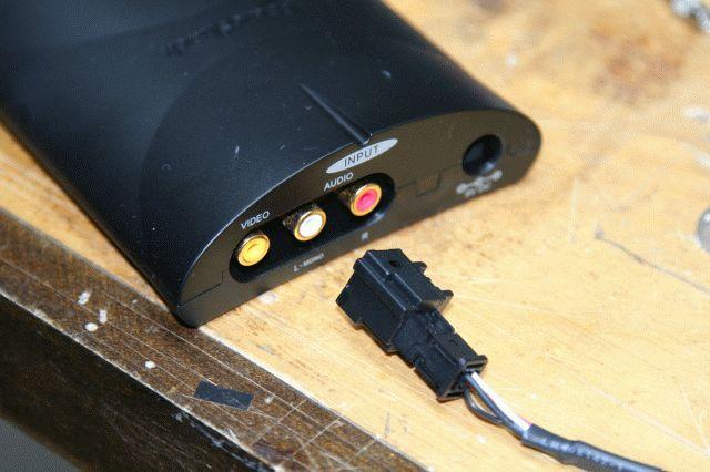
OK, so we took care of the output of the ADC, now we need to work on the input to the ADC, which comes from the DICE unit. As you can see in this photo, the DICE harness is not symmetrical:
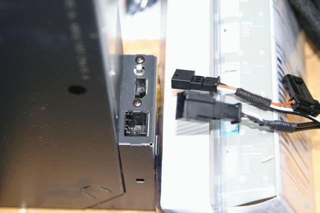
The harness has one side going to the DICE:
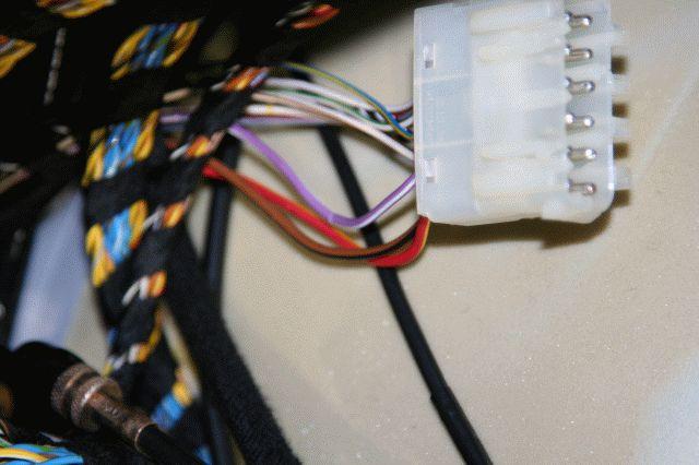
and the other side is what hooks up to the cars CD Changer terminals/connectors:
The CD Changer connectors are normally the 3-pin power and data/control cable, and the 4-pin analog audio (left and right channels), so now that we have the ADC to deal with the analog signals, all we need is to make these two work together:
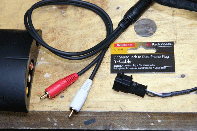
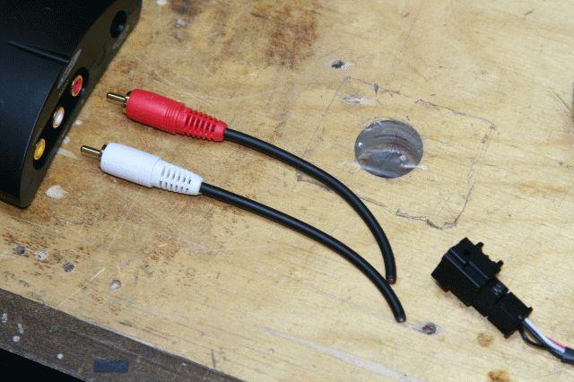
I just bought a cable from Radio Shack that had the end points I needed, but you probably can make your own as well:
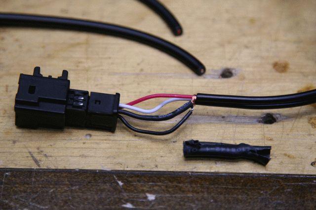
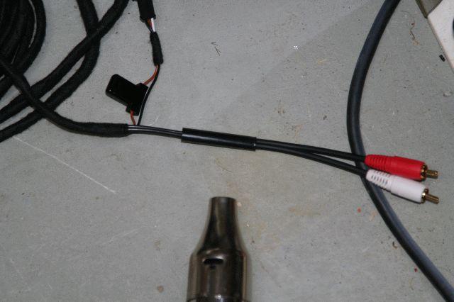
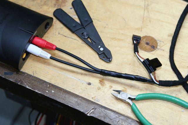
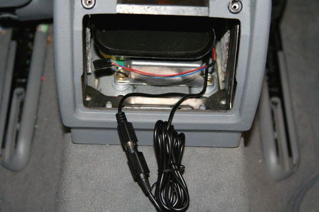
So now we have completed the Analog to Digital Conversion module which “fixes” the DSP “problem”. Everything else in the install is right out of the DICE install manual !!!
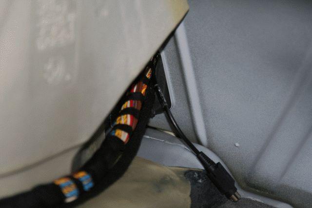
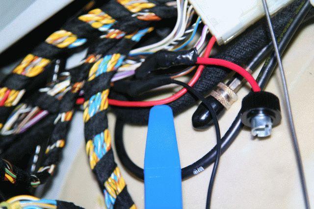
Now, to power the ADC, we need to find switched power (only with the key in the ignition) and ground. I found the right cables in the pre-wired Cell Phone harness our cars come with. I of course tested this before going further:
The violet with white stripe is the positive wire, and the brown with the black stripe is the ground wire:
I never, ever use those grabby things – I always solder everything instead. Better grounds and no chance for stuff to come undone or loose after being on the road for a while !!!. Here is the inline fuse (1/2 Amp slow acting, as the ACD needs only 200-300mA), and the ground wires already soldered and ready to go:
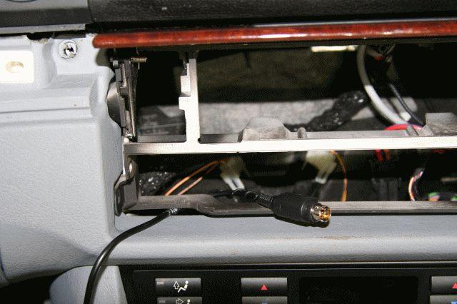
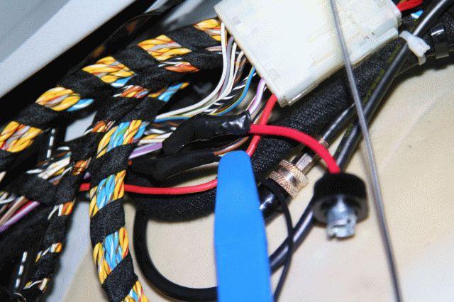
We then connect the 3-pin from the DICE to the 3-pin from the car (that used to be connected to the CD changer), and then we have everything ready for testing it for the first time:
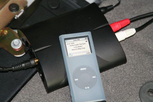
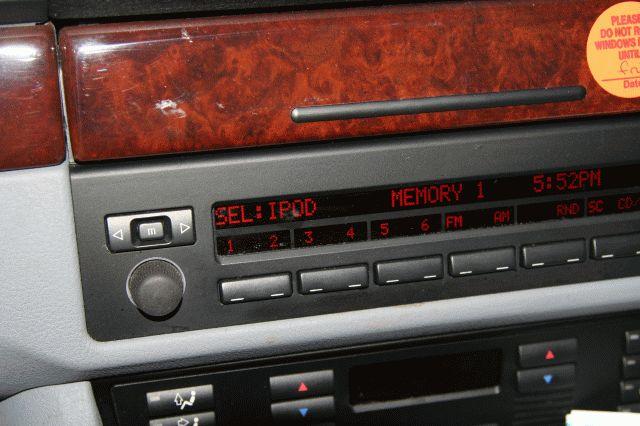
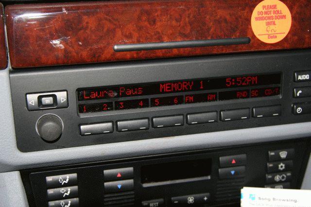
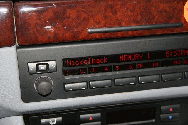
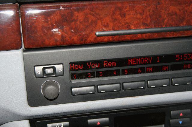
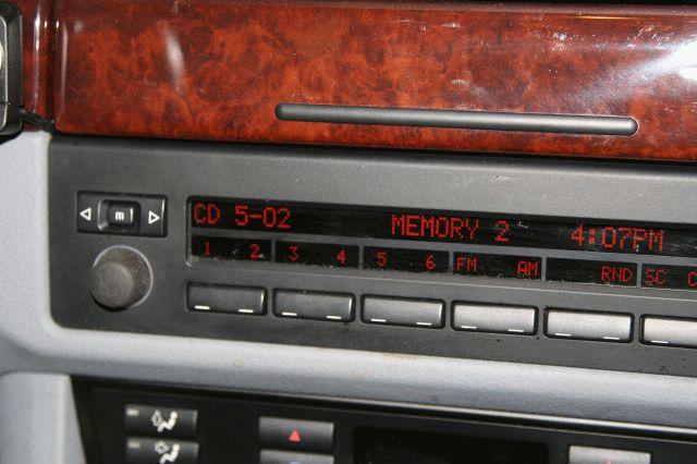
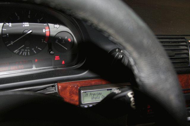
Read the DICE manual. Using the DICE module is very easy if you take time to read the manual. Basically, you select DISK 1 for listening to music. You use your steering wheel controls for going backs and forward. You use the other DISK buttons in your radio control (MIF) to make other selections, including selecting the IPOD vs. the aux input (IPOD selected here):
plus you also have the choice to select what type of display your BMW has to that the DICE will send the right commands/data to match it, as shown in my own car. Just like the DICE manual said, everything worked like a charm:
Part 2: Adding XM Radio via DICE
As I mentioned earlier, the DICE has an aux input, as shown here, So all I need to do know is to find an XM System that has standard RCA stereo outputs and I am set!:
After 1-2 weeks of research I end up selecting the XM Commander system. This one has a receiver and connections module that goes in the trunk, and a “Command Module/Display” that goes in the front of the car, that looks like this:
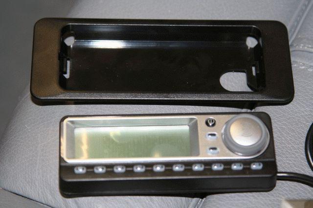
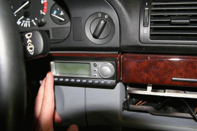
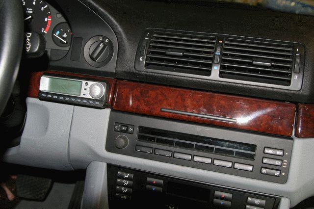
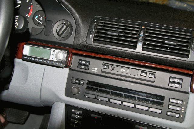
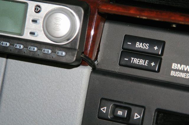
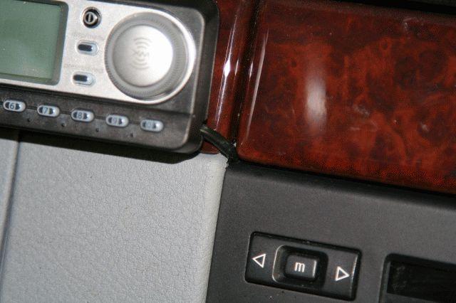
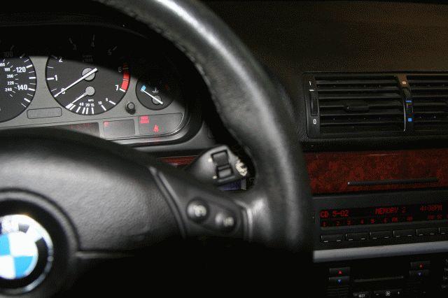
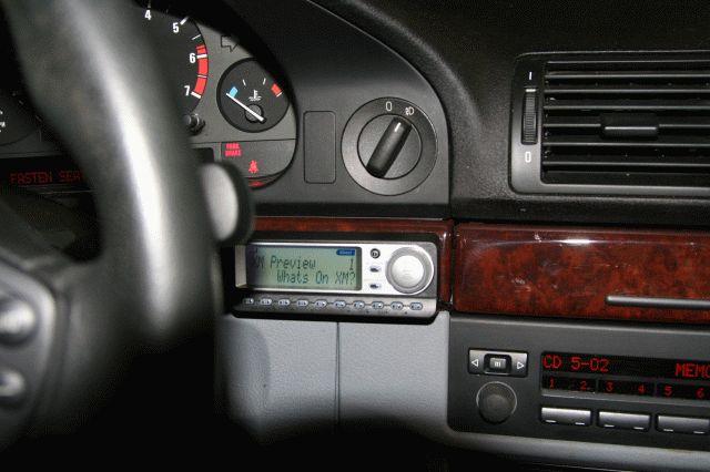
For now, until I figure out a better place, I am installing the display module here on the left “wood” trim piece (more photos later):
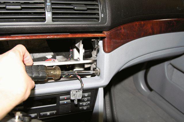
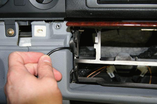
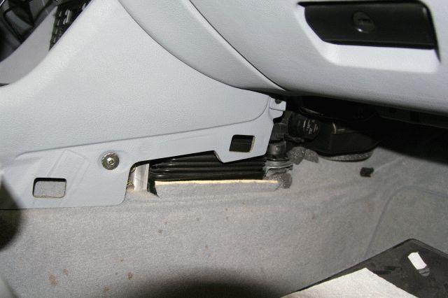
First I needed to find a way to hide the cable as best as possible, and then to route the cable to the trunk, so I started removing “parts” that were in the way:
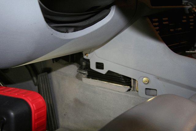
I loosed up the metal harness, enough to get the plug from the display module to go through from the front to the back:
This is where for now I am getting the cable to go:
and the display will look like this (I am using some simple Velcro to keep in place):
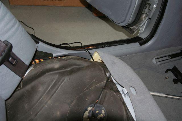
To start the routing of the cable I looked at both sides of the front center console, but decided with the passenger side:
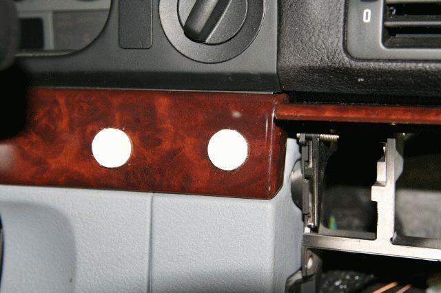
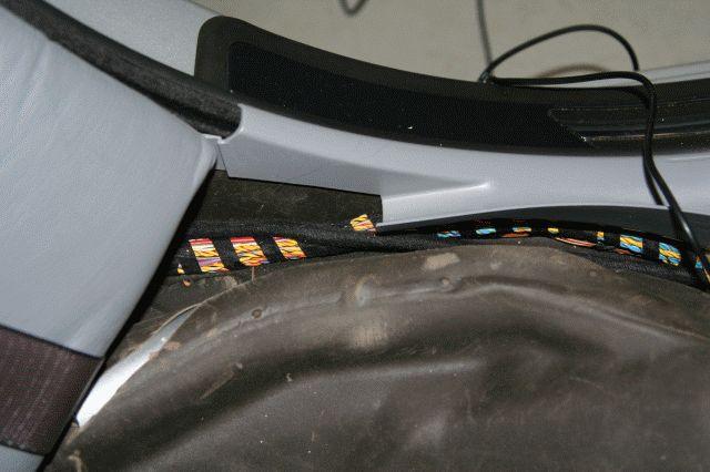
I had to trim the plastic a little in order for the cable not to be pinched/cut when I re-install the Cassette and Display pieces (these cuts are hidden once everything is put together for that all-to-important factory look!):
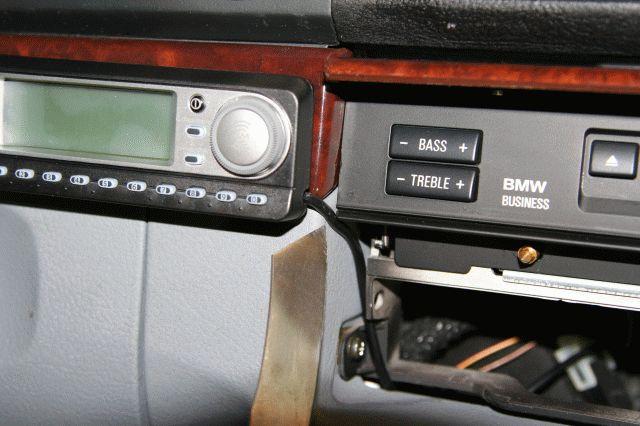
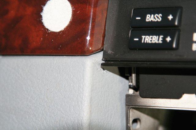
I unfortunately scratched up a little the left plastic edge of the Cassette module, but with the cover close you will never see it:
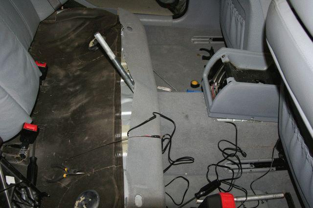
OK, so lets go on routing the cable. I loosened up the center console by removing all of the rear screws, as well as the rear seat (Bentley manual and BMWtips come handy here!), which gave me enough room to “play”. I used a hanger to pull the cable on the right side of the center tunnel, although I used a metal rod to “convince” the carpet to give me more room to route/move the cable:
Since the cable was getting short and this kit comes with an extension cable, I decided this was a perfect place to use the extended cable. As you can see here, I can hyde everything under the rear vent:
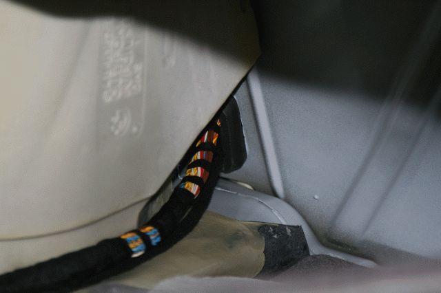
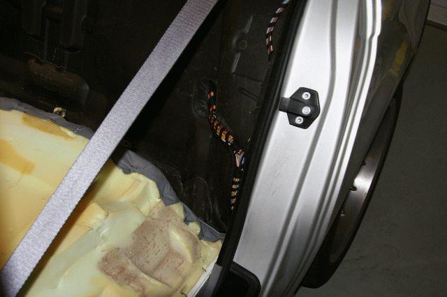
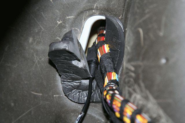
I then proceeded to route the cable towards the rear left side of the car since I want to share the same path the rest of the stereo cables use/take:
From the trunk side, I have to remove the left side panels, to reveal the place were the cables enter the trunk. Here it helps to remove the upper rear seat:
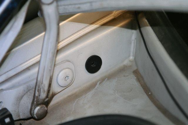
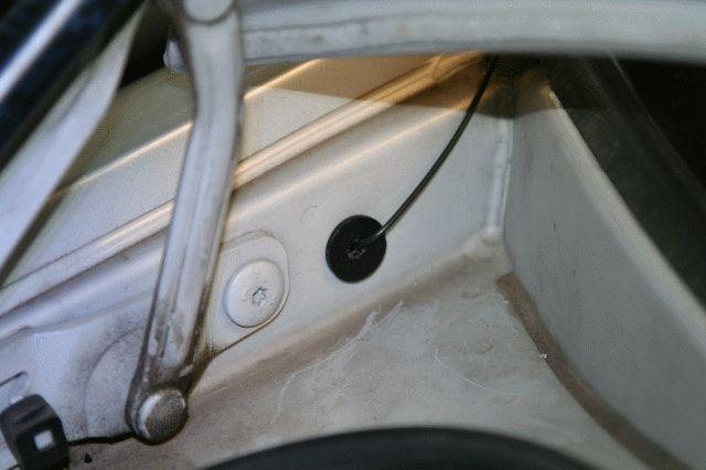
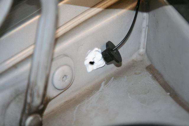
I will get back to the stereo cables later, but I wanted to talk about the “painful” part of the install – where I give my “new-to-me” car a new hole – for the antenna. I decided to make it water tight and use a “sort-of-grommet”, which I will seal with silicone:
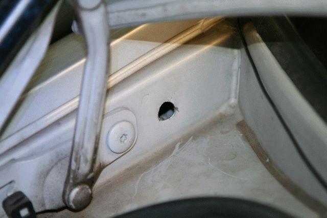
Of course I had to disassemble the actual antenna connector so that I would have a smaller diameter to deal with. After all, if I am making a hole in the car, might as well try to get away with the smallest hole possible!:
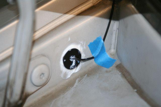
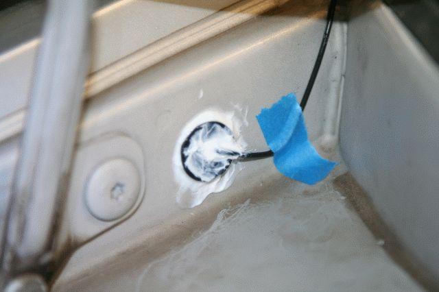
I then used the same silicon (looks white here but it dries out clear), to keep the antenna cable in place along the edge of the rear glass (the actual antenna is magnetic on the bottom so it stays put on its own):

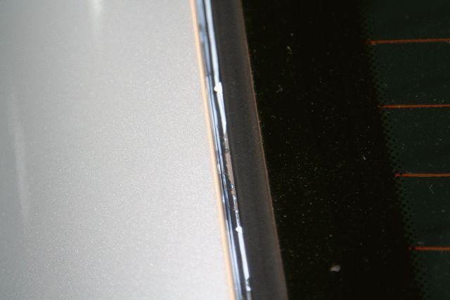
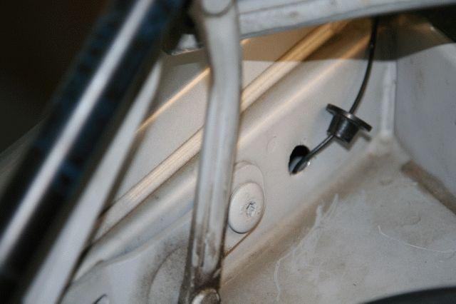
I made a slight bend so that the bottom of the cable is lower than the grommet home, so that water driping goes into the “normal” drain path and not into the grommet. Probably an overkill since everything is sealed with silicon, but it certainly does not hurt!:
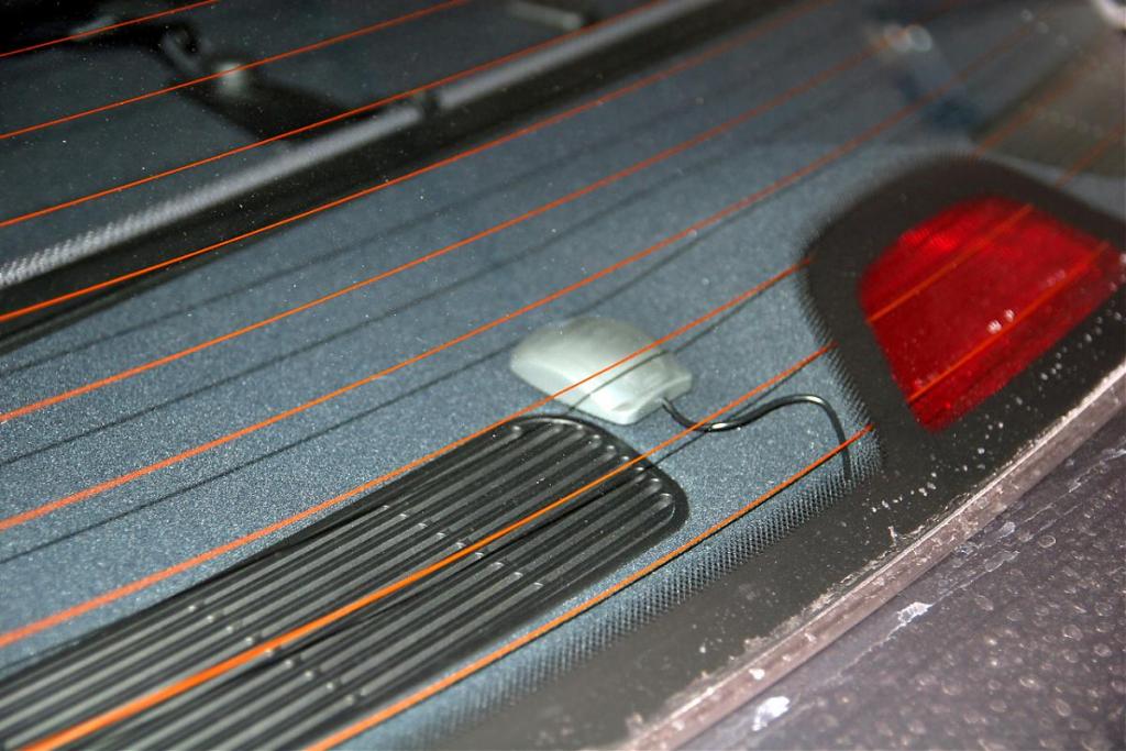
EDIT: Roadfly Forum Member "steve" found that the XM Antenna works from within the inside of the car as shown in this picture of his install. It is prudent to try this route first before making a hole for the antenna as I did. Thanks "steve" for sharing this alternate install step:
OK, now that the antenna part is almost done, we can talk about the wiring for the XM Module. From part 1 above, this cable has switched power (ACC and ON positions only):

This one has battery power (ON all of the time)
and this is ground:
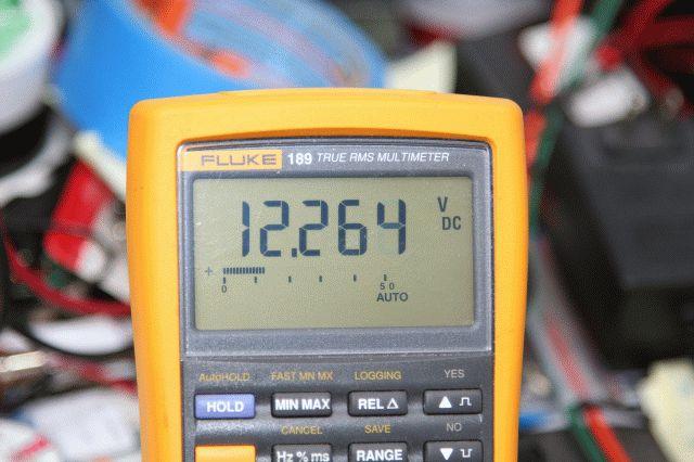
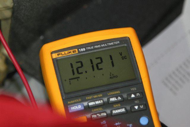
Here I am using my trusty Fluke M189 to verify polarity and that I have the right cable:
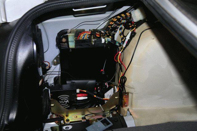
You can see here on the lower left the XM Trunk module. The antenna connector is hidden in this picture, but it is on the lower left side of the XM Module – I placed the module this way so that the stereo/power connectors were on the right side so that they would be easier to place/route:
I got lucky and everything worked perfectly the first time around – I even got a Satellite signal inside my garage!. I first tell the DICE module by using DISK 5 that I want listen to the AUX input (#2 as #1 is for the iPod), and viola:
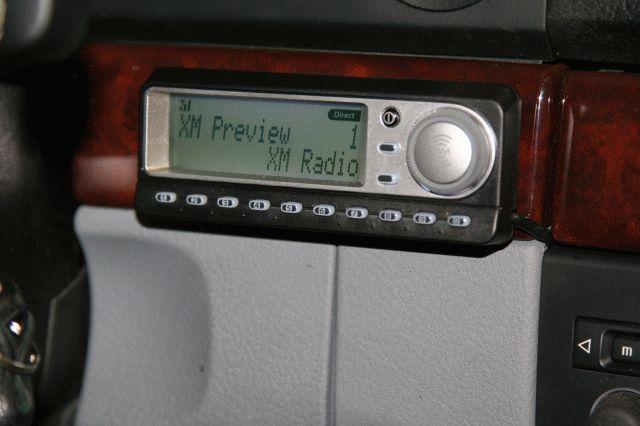
The position is not ideal since the Steering Wheel blocks some of it depending on the angle, but it is out of the way and it is easy to reach for the controls and memory buttons, which is what I use the most:
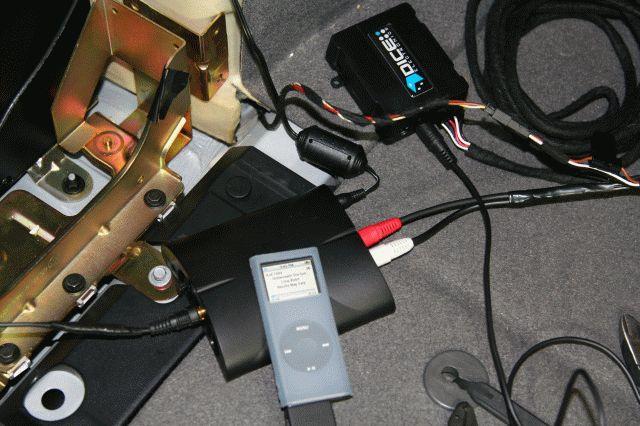
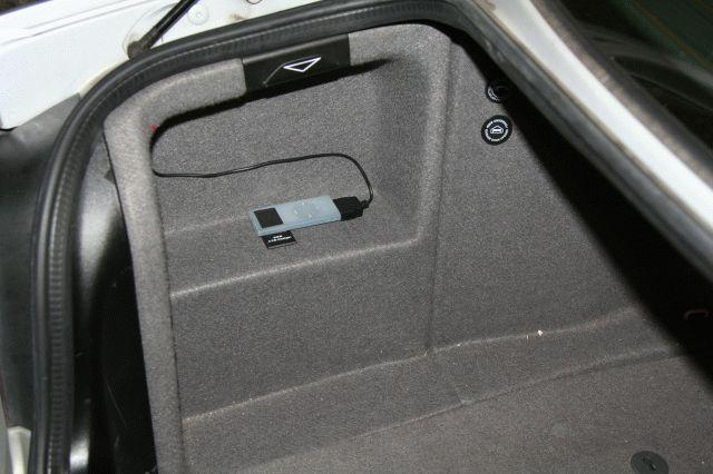
Back on the trunk everything looks normal, and I used the hook side of the Velcro to keep the iPod from moving (I don’t need to have it up-front with me since I have access to it via the Steering Wheel/Stereo buttons up-front!):
That is all. I hope this was helpful ***61514;
William Quiles
April 14, 2007
Tools/References/Links:
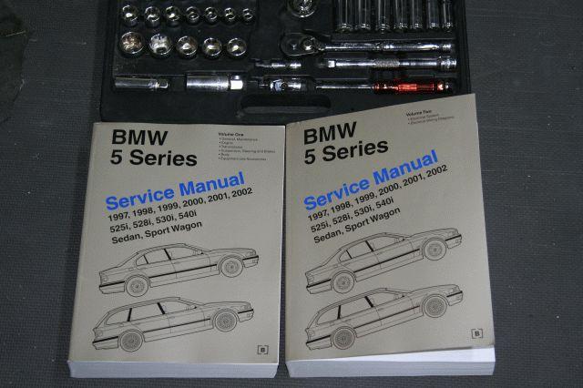
- Bentley manual:
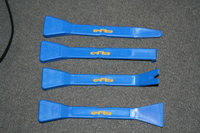
- European Auto plastic trim removal tools (definitely worth the money !!!):
- Wiring Diagrams from BMWtips, like this one:
- Cables and “stuff” from Radio Shack: