You must be logged in to rate content!
15 minute read
E39 540 Full Front Suspension Rebuild – Learnings – Tips – Gotcha’s
Compliments of KeithS @ www.bimmerfest.com
While this is not a full DIY, it will cover all the basic steps and should help others who are planning this job. Had I known now what I am about to write, I could have cut the time in half and saved some frustration. If I did this again, think it would take about 5 hours. While some of this information may be useful to those with a 6-cyl, much is unique to the V8 (especially the gotcha's) with the recirc ball steering. Use this at your own risk, no guarantees apply, just trying to help others.
The patient was a 2000 540iT with sport suspension and 123K miles. The front end is exactly the same as the sedan. The front suspension was all original except for shocks (changed 20K miles ago) and the thrust arms were replaced once before at 60K. The symptoms was a bad shimmy between 45-60, especially first thing in the morning (until the tires get round again from sitting overnight), shimmy at random other times, and unusual knocking sounds when driving a low speeds on a straight road. Also thought the steering was not as crisp as it could be.
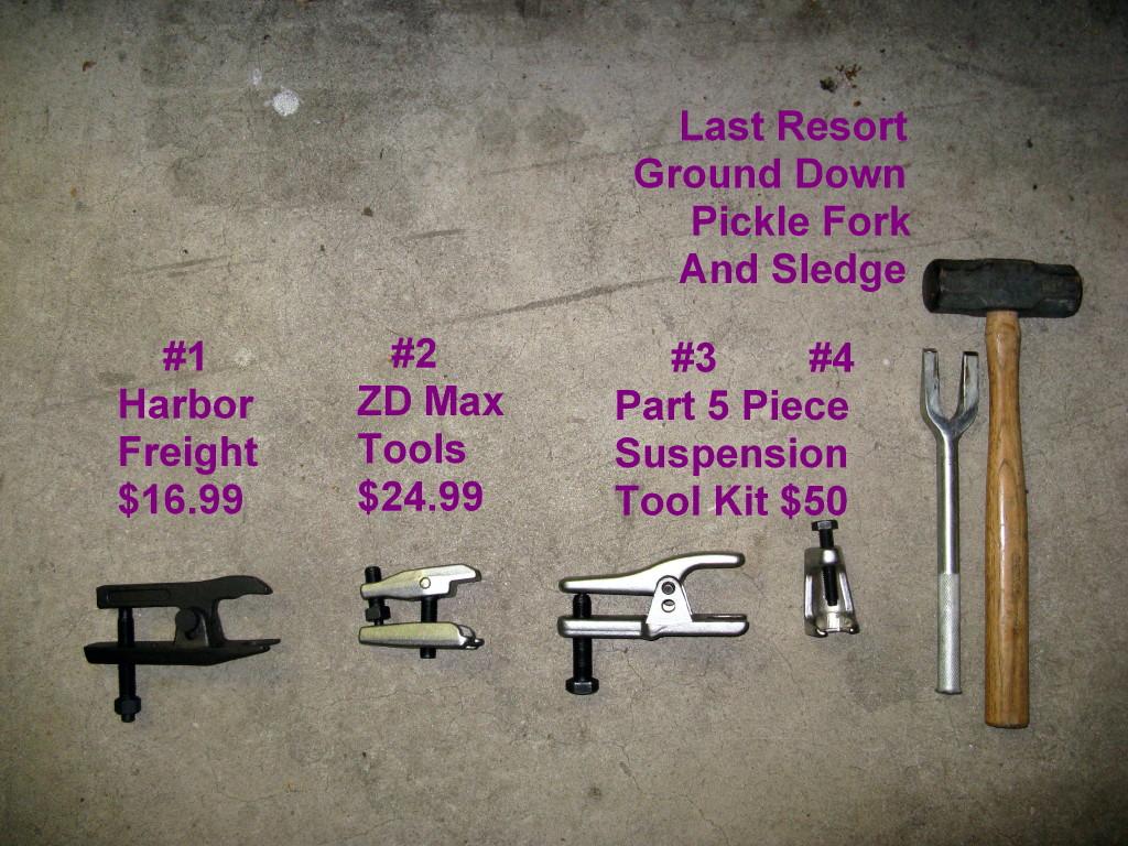
Having the right tools is critical, and if attempting yourself, of course safety first, always use secure jack stands before getting under the car. Popping off the ball joints/tie rods is always one of the more difficult aspects. Most parts stores and even club mechanics swear by a pickle fork and a sledge hammer. Sorry not for me, it almost never works, and I do not like beating the crap out of the car or myself. Thusly I was armed with an assortment of ball joint tools (see pic #2). In the end the one that worked the best (for most the joints) was the $17 tool from Harbor Freight. Also used the tie rod tool, #4 in Pic #2.
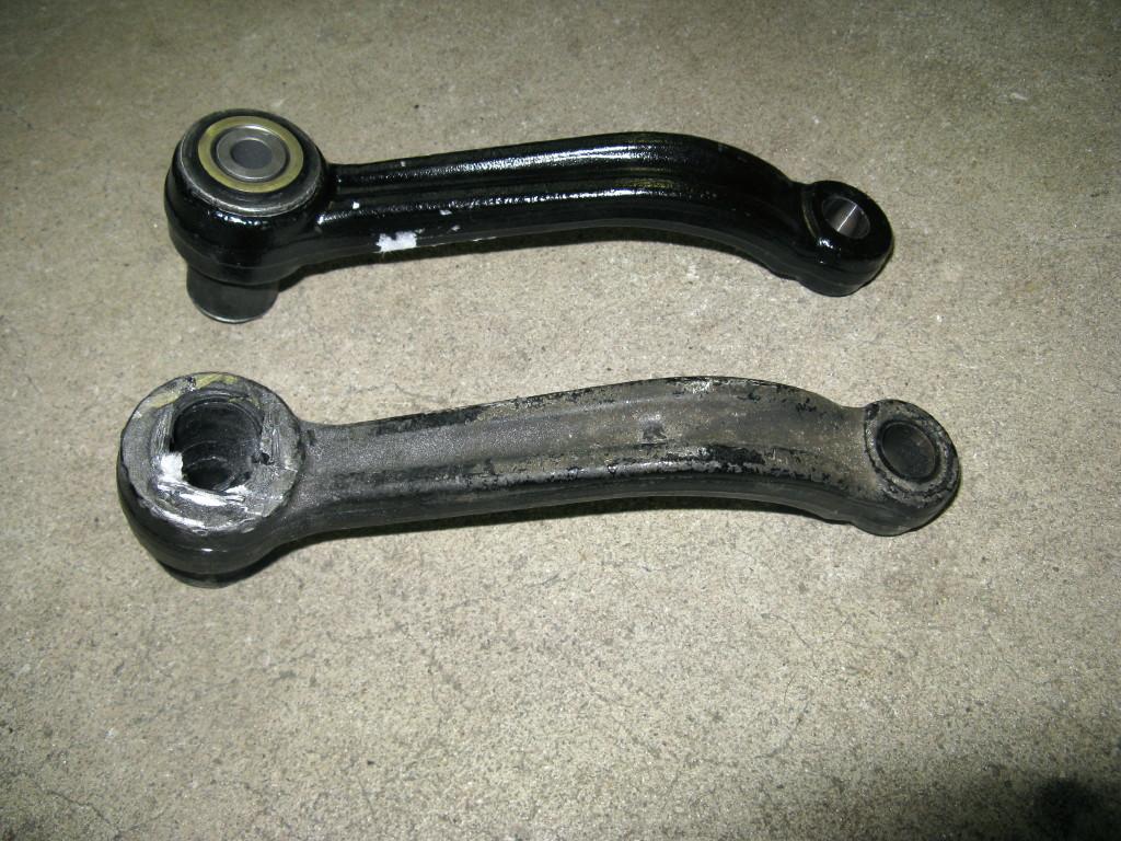
Let me get right to the 2 gotcha's, at least for me. Thought I was going to save a few $$ and just replace the replaceable bushing in the idler arm. I've change bushings many times in the past with no issues. After an hour of pounding using a 5-lb sledge hammer and even trying a sawsall to cut the bushing out, I gave up. All I ended up doing was destroying the bushing, getting myself tired, and it would not budge for anything. Unless you have access to a very strong press, forget it. In picture #3 you can see the one I destroyed and the new idler arm with bushing already installed that I purchased (fortunately in stock at one of the local dealers).
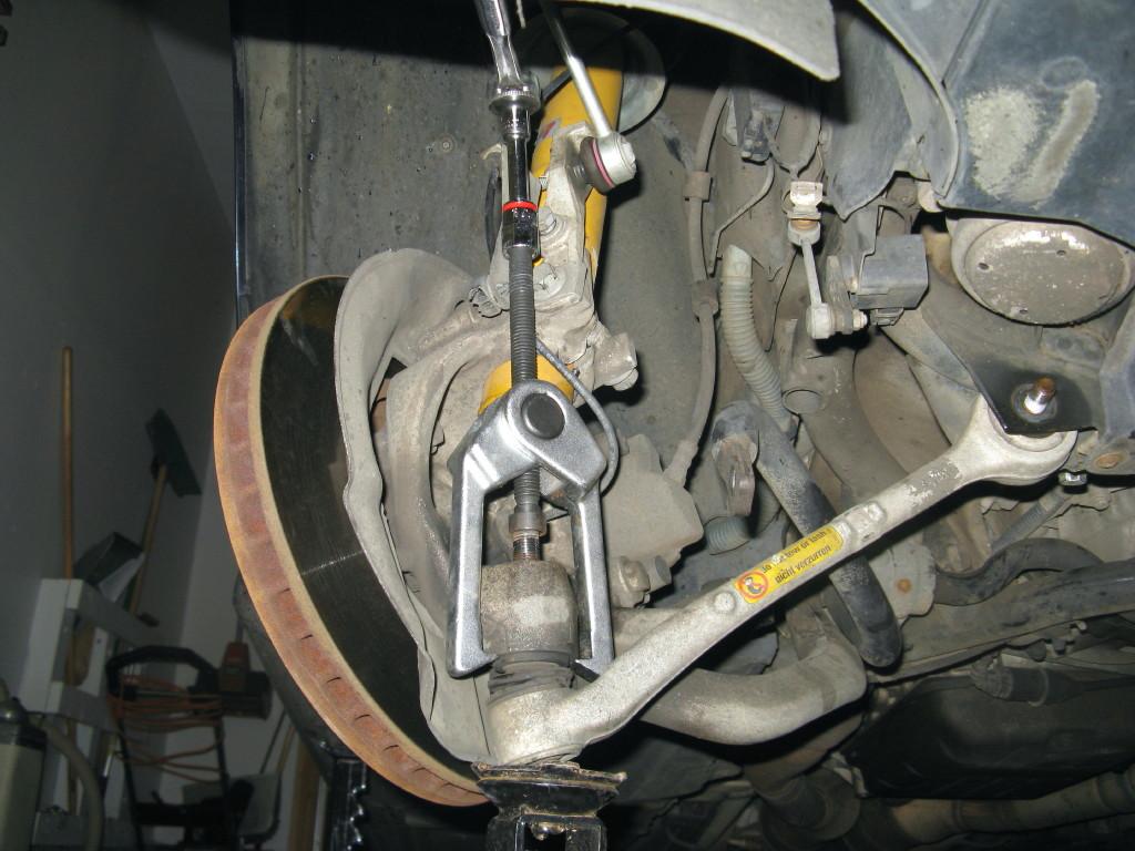
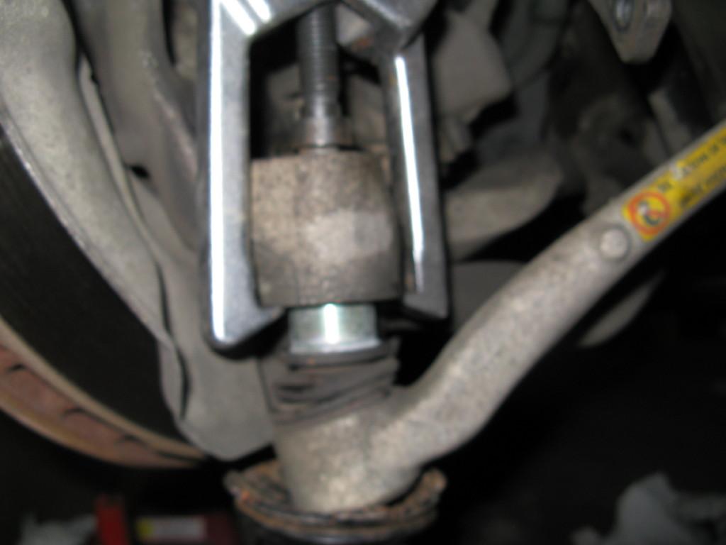
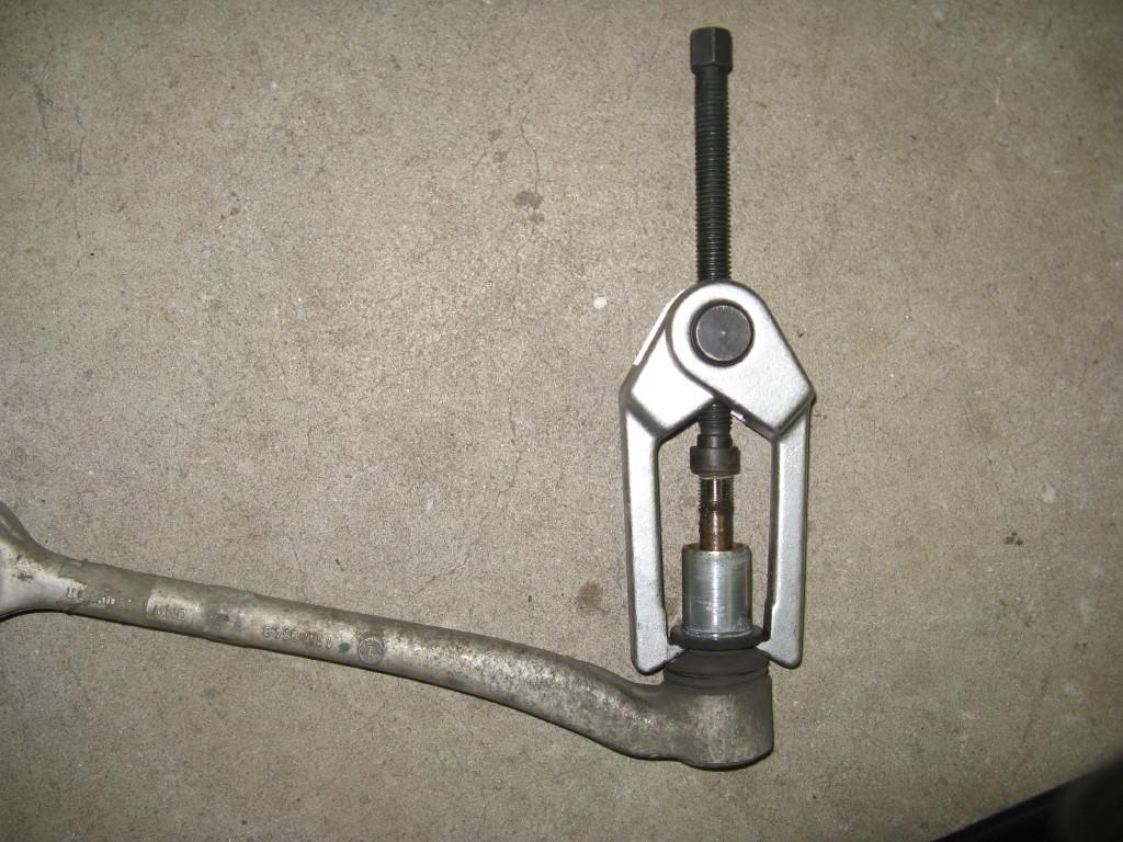
Gotcha #2. As I indicated the harbor freight tool worked great on most (but not all) the joints. The ball joint of the control arm (front most joint in the 540) is unusually tall. It requires a ball joint tool with an opening of at least 3". I had 3 tools and none of them were larger then 2-1/2", and no one sold one locally that was larger either. (I even tried cutting off the bolt to make it shorter but with the smooth top the tool would only pop off). My solution (Picture #8) was to use a gear/pulley puller I had, which was more than tall enough (you do need to slide the steering knuckle down on the shock for clearance). When using this tool there is actually an insert that holds the ball joint and that insert came out easily with the joint (you can see in Pic #9). Once removed from the car the insert was easy to separate from the ball joint (Pic #10) and you just tap it back into the steering knuckle.
General tips:
- You will have to drop the steering knuckle down on the shock to have access to the bolts, have room to put in the ball joint tool and be able to get a torque wrench in there.
- You will need to unbolt the sway bar bushings for needed clearance to the thrust arm mounting bolt
- You will need to turn the wheel from time to time to move the tie rods to get the need clearance to do things.
- It is possible to remove the entire tie rod assembly in one piece
- For the ball joint and tie rod pullers, make sure they are all the way on and have a full bite. If not you may break the tool or it will go flying off. You will actually have to hammer them into place.
- For the ball joint and tie rod pullers, give them time, they usually do not work immediately. Do not just keep making tighter until things pop (else you may be hearing the tool breaking). Also put some grease on the threads of the tool. I only used regular ½" socket and one arm, never 2, and not a breaker bar. Tighten them down pretty tight and wait a few minutes (you can spray the joint with liquid wrench, pb blaster, etc). After a few minutes tighten some more. Each minute tighten again. It will usually pop off (with a LOUD bang) while it's just sitting there. If you feel its getting excessively tight, try hitting the part (control arm, thrust arm) with a metal hammer. The vibration also helps it to pop off.
- All the nuts are one time use locking nuts and should all be replaced. Most (but not all) are included with the new parts.
- In some cases the ball joint studs will just spin when you try to tighten the nut. This is expected and there is a hex opening at the top of the stud to put in a metric allen wrench or fitting. You hold the stud with the allen tool and using an open end wrench (can't use a socket) tighten until it stop spinning. You will then be able to use a socket with your torque wrench for the final tightening.
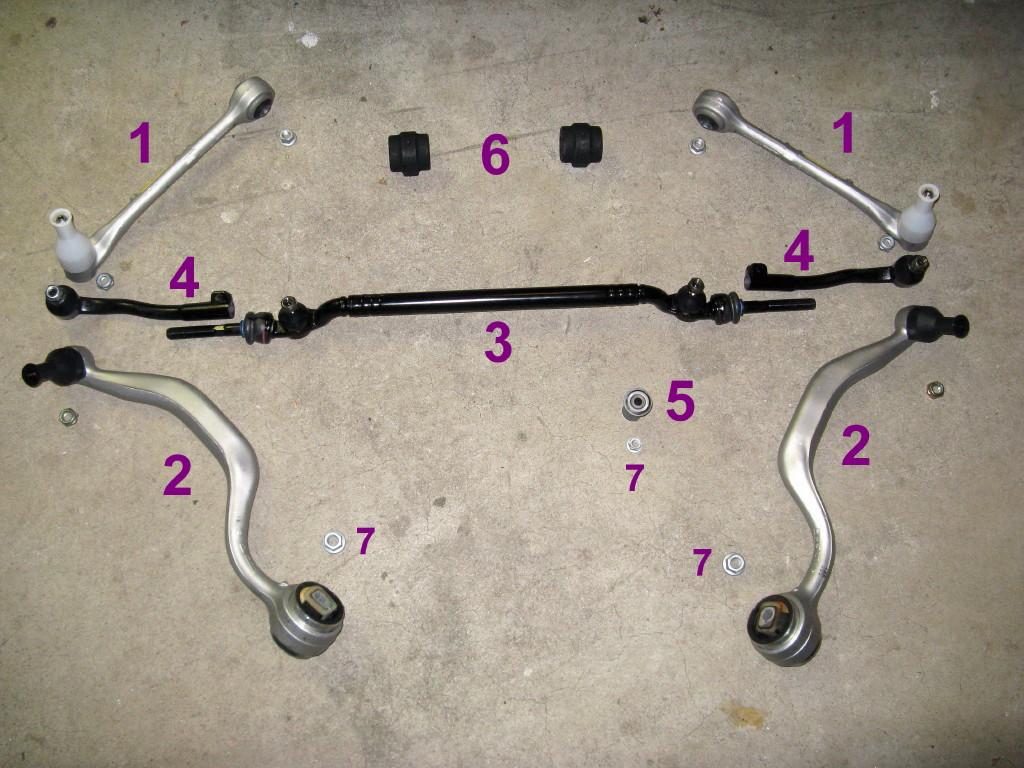
In Picture #1 are the new parts (Except the idler arm purchased later). Total was around $900. Obtained from 2 on-line vendors:
- #1 Control Arms – Lemforder, Part #s 31121141961, 31121141962
- #2 Thrust Arms (Traction Strut) – Lemforder, Part #s 311211092609, 311211092610
- #3 Center Tie Rod – TRW (OEM supplier), Part # 32211096059
- #4 Outer Tie Rod (Ends) – TRW, Part #'s 32211091723, 32211091724
- #5 Idler Arm Bushing, part # 32211136452, but I needed to get the whole steering arm assembly in the end Part # 32211141592
- #6 Sway Bar bushings
- #7 These new self locking nuts were not included with the ordered parts and obtained separately, 1 steering arm mounting Part # 32201092453, and 2 nuts for Thrust arm mounting Part # 33306760349
More or less the steps. Not the order I actually did them in but what I think would work best now that I've done it:
- Measure from the center of the wheel to the wheel well opening (you will need this later)
- Jack up front, high as safely possible and put on jack stands, remove front wheels.
- If you have Xenon's disconnect the height sensor NOW so you do not break it (connected to right control arm)
- Disconnect sway bar end links. Remove sway bar mounting bushing covers
- Remove the 3 nuts on each of the wheel carriers (one each for tie rod, thrust arm, control arm). You can get the center one with an open end wrench.
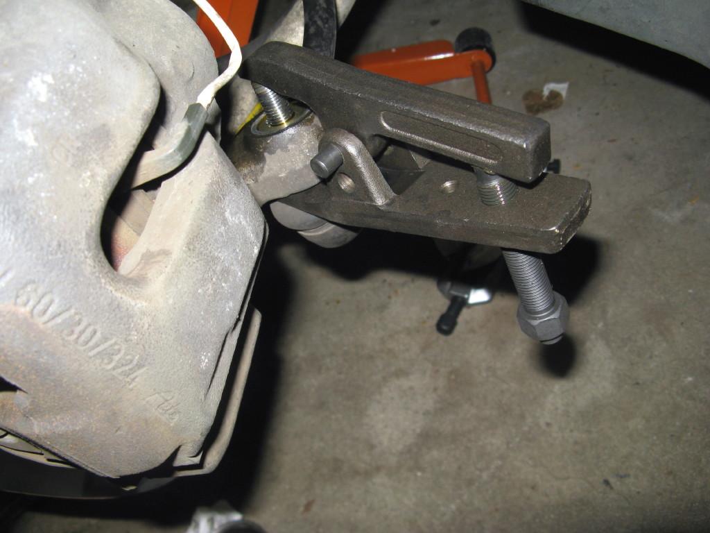
- Pop off the tie rod end ball joints on each side. See Pix #4 for properly positioned ball joint tool.
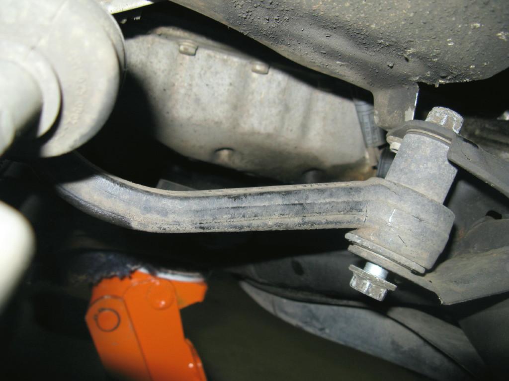
- Remove steering arm mounting bolt – See Pix #5.
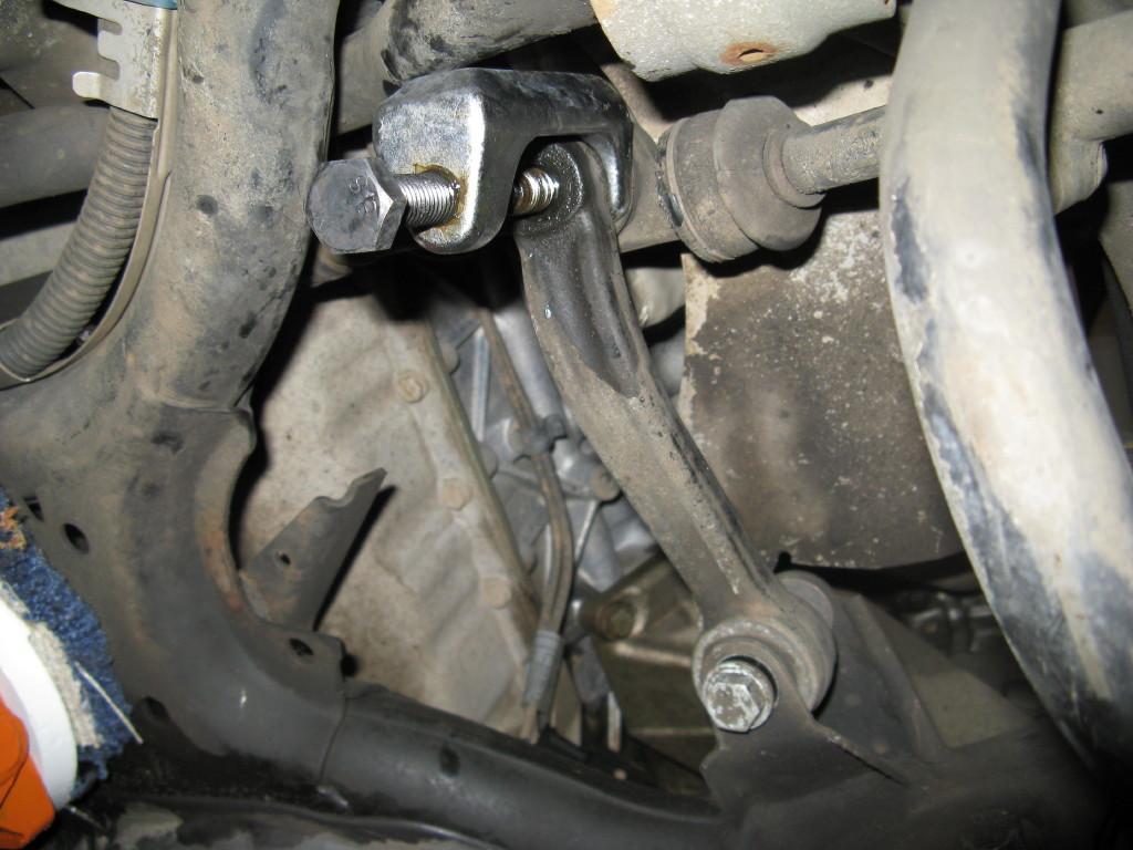
- Pop off steering arm from tie rod. See Pix #6 for properly positioned tool. Remove steering arm
- Pop off tie rod from pitman arm – See Pix #6 for tool use.
- Remove tie rods as a complete assembly by sliding out one side.
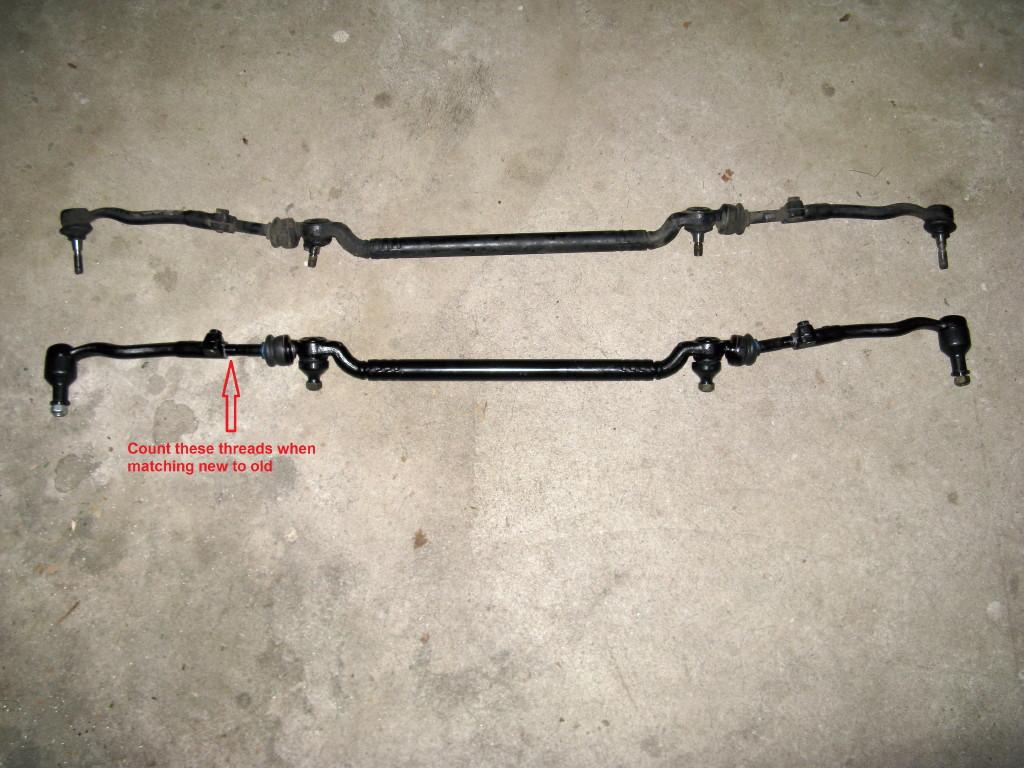
- Assemble new tie rod with ends and compare to old. See pix #7 of old/new comparison. (Note the tie rod ends are pointed in the opposite direction than the picture when installed in the car). Use anti seize compound on threads. Try to make it match as close as possible in length so alignment is reasonably close. I found it was best just to count the exposed threads of the center tie rod to each of the tie rod ends of the old and make it the same in the new. Tighten the nuts securing the tie rod ends to the center rod. Set assembly aside for later.
This is indicated for one side, repeat for the other:
- Loosen and remove the nuts where the thrust arm and control arm mount to the body (leave the bolts in place)
- Mark the alignment/location of the wheel carrier pitch collar to the shock (for future reference)
- Loosen the wheel carrier to shock pitch bolt and slid the carrier down on the shock about 2" You may need to use a jack to keep it from falling to far down.
- Pop off the control arm ball joint, this is where I had to use a pulley puller – See Pixs 8 & 9.
- Pull out control arm to body mounting bolt and remove control arm
- Remove metal insert from control arm (if needed – See Pix #10) and tap back into steering knuckle
- Install new control arm. Only loosely tighten the body mounting bolt/nut, it will be fully torqued later in a different step. You can fully torque the control arm ball joint nut now (or later with thrust arm) – 59 ft-lb.
- Repeat process for thrust arm. See Pix #4 for properly installed ball joint tool. You can fully torque the ball joint now – 59 ft-lb.
- Using a jack lift the wheel carrier back up onto the shock noting the marks you made before as to alignment with the shock. You can jack on the thrust arm ball joint. When back into place tighten the shock pinch bolt – 60 ft-lb.
- Lift the wheel assembly further with the jack as to compress to normal resting height. This is the measurement you took before between the center of the wheel and the underside of the wheel well. On my car it was 14.5". Make sure the jack is secure, there will be a lot of force, but in no way should the car be lifted off the jack stands. When at the "normal" position, fully torque the arm to body mounting bolts, 81 ft-lb for the tension strut, 58 ft-lb for control arm. If possible do this with the wheels in the straight ahead position. Access is tight/difficult on the thrust arm, especially with a jack in the way.
- Release jack and repeat this section for the other side.
Now all the suspension components should be fully installed and it's time to install the steering components:
- Slide in the tie rod assembly you made up before. It is expected you will need to twist the ends to get the needed clearance.
- Insert the tie rod into the pitman arm (goes in from above with stud pointed towards the ground) and install bolt and tighten – 48 ft-lbs. You may need to turn the wheel to move the pitman arm to get the needed clearance
- Install the steering arm. Again you may need to turn the wheel to move the assembly to get things to fall into place. Idler arm to frame 46 ft-lbs. Center tie rod to idler arm 48 ft-lb.
- Install and tighten tie rod ends into wheel carriers and tighten to 48 ft-lb.
At this point all the new parts should be fully installed:
- Reattach the sway bar bushing mounting covers, and reattach the sway bar end links - 44 ft-lbs.
- Re clip the Xenon height sensor (if so equipped)
- Install tires, lower off jack stands
- Test drive
- Get the car aligned
Just got back from the alignment, was pretty close just by counting the tie rod threads. The toe is suppose to be 07' (minutes - 1/60 of a degree) on each side, I had it at 16'. The rebuild has delivered what I wanted. Shimmy is gone, steering is tighter, handles great, and I did not hear any clunking. The more I drive it, the more improvement I notice. Now needs much less minor constant correction to stay exactly in the lane.
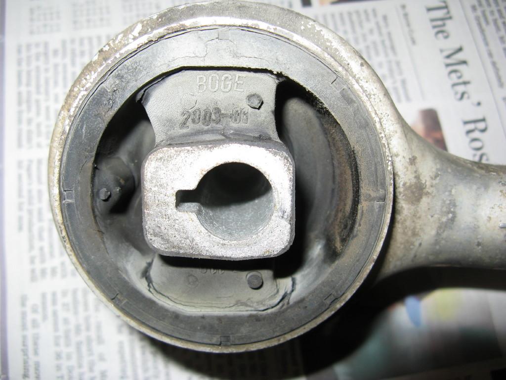
Looking at the parts removed, with the exception of the cracks in the thrust arm bushings (source of shimmy See Pix #11), none of the rest of the parts seem to be in terrible shape. I guess the system is a sum of it parts. So even a small amount of wear in multiple parts will add up. The joints on the left side of the tie rods (nearest steering box) were a little loose, right side still tight. Some of the other ball joints were still tight, some well broken in, but not terribly loose.
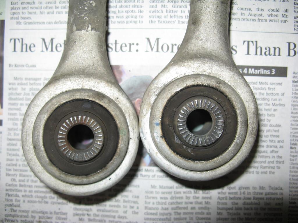
Picture #12 is the bushing in the control arms, not to bad for this age/mileage.
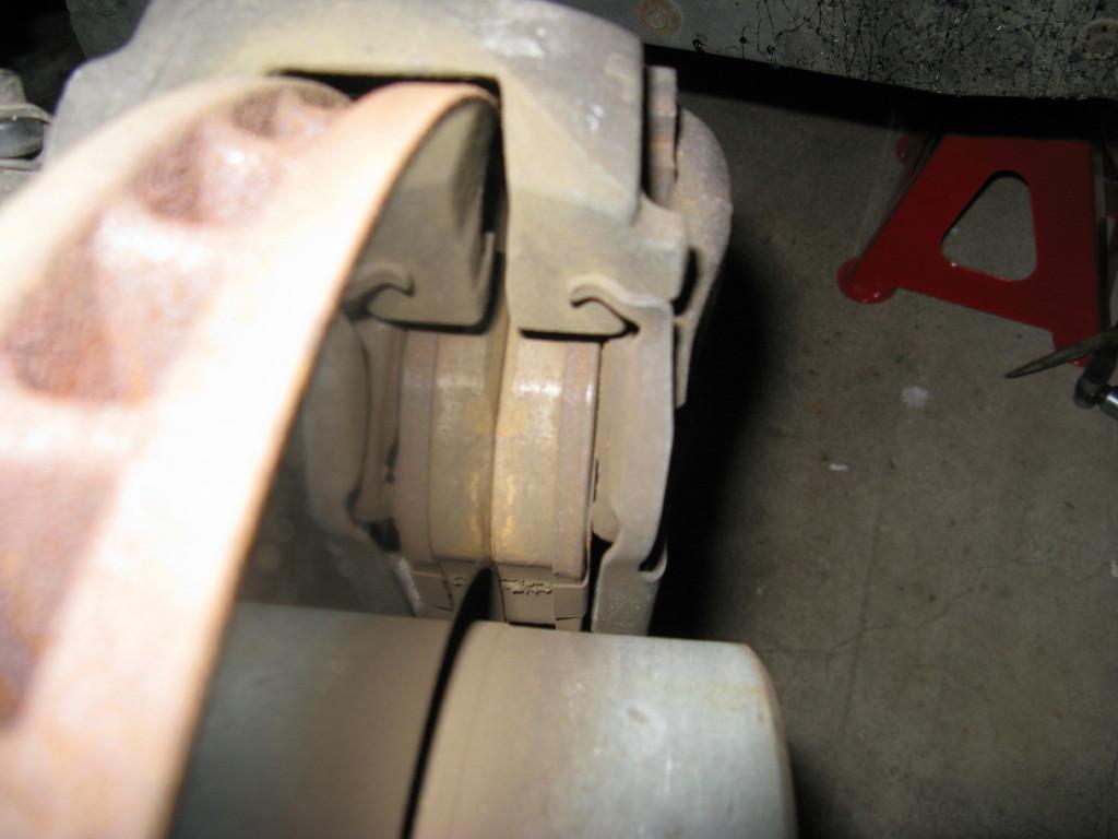
Threw in Picture #13 for interest. These are Akebono Euro Ceramic pads with 25K miles on them. On this car the front OEM pads lasted about 30K miles. At 25K miles the Akebonos still have over 10mm of pad left, or are used less then 25%. Also notice the smooth finish on the rotor and lack of any visible wear.
Picture Descriptions:
- #1 All the new parts
- #2 The Assortment of Tools
- #3 Old & new steering arms with bushing
- #4 Ball joint tool properly installed
- #5 Steering arm chassis mounting bolt loosened
- #6 Tie rod joint remover properly installed
- #7 Old and new tie rod assemblies
- #8 Gear Puller used to remove control arm ball joint
- #9 View of insert/sleeve on ball joint
- #10 Gear puller being used to remove sleeve
- #11 Close up of cracked thrust arm bushings (typical source of E39 45-60MPH shimmy)
- #12 Close up of control arm bushings (not bad for 123K miles)
- #13 Akebono Euro ceramic brake pads on front after 25K miles
Pix #1 Front Suspension New Parts Annotated
Pix #2 Front Tools annotated
Pix #3 Old and new steering arms
Pix #4 Properly installed ball joint separator tool
Pix #5 Steering arm to body mounting bolt loosened
Pix #6 Properly installed tie rod joint separator tool
Pix #7 Old and new tie rod assemblies
Pix #8 Pulley puller being used to remove control arm ball joint
Pix #9 Control arm coming out with sleeve attached
Pix #10 Removing Sleeve from control arm ball joint
Pix #11 Cracked thrust arm bushing 60K miles
Pix #12 Control arm bushings 123K miles
Pix #13 Akebono Euro Pads on front with 25K miles