You must be logged in to rate content!
13 minute read
S60R / V70R HOW-TO: Replacing PCV Breather (Crankcase Vent)
Compliments of vLGrok @ forums.swedespeed.com
6-16-2012
DIY: Positive Ventillation Crankcase (PCV) Breather Box: P2 VOLVO 2004 S60R
*** NOTE: You don't need to do ALL this (or even most of it) for just PCV system.
*** I did a lot of other things at the same time. Relax, and see some of the replies,
** which offer shorter list of steps for complete PCV-only job.
While you can piece it out, I purchased this kit to save me time researching parts:
PCV Breather System Kit from IPD
Still TO-DO in writeup:
Turbo Inlet Pipe
Positive Crankcase Ventilation Box
Banjo bolts (2)
Water pipes
P R O C E D U R E S:
Removal and Disassembly
P101 Disconnect Battery
Disconnect negative (black) battery terminal.
P102 Engine Mount Bar removal
Loosen upper engine mount with 15mm shallow socket and and 18mm wrench.
Remove the 14mm bolts on the 2 mounts at either end of bar.
Remove bolt from upper engine mount and remove bar.
Insert the mount bolts back into the holes for storage or plastic bag them.
P103 Charged Air Pipe removal
Loosen worm clamp on intercooler side and slip hose off pipe. Insert shop rag into hose to block.
Remove the two CAP mounting screws. Front is a Torx 25, back is 10mm.
Using 4mm Allen key, loosen screw on clamp holding CAP to Turbo.
Stuff a clean shop rag halfway into turbo to prevent entry of foreign objects.
P104 Engine Covers removal
Torx 25 remove all 8 bolts from spark plugs cover, remove spark plugs cover.
Torx 25 remove the 2 bolts from timing cover, unclip cover from front, then back, and remove.
10mm socket, remove 2 caps from Fuel Rail cover. Place all these 12 bolts together in a plastic baggie.
(optional) Spark Plugs, you're there already. Do not fail to check the gap, 0.028 !
(optional) Upgrade the Ignition Coils.
P105 Electric Fan removal
Disconnect the fan electrical power.
Remove the two 10mm mounting bolts from either side of fan at top.
The fan lifts up and out, supported by heavy clip on either side. After lifting up 1 inch, you can remove fan assembly.
WARNING: Be very careful not to hit the radiator as you're lifting fan out. (This may be where I damaged my radiator, $$$ to replace)
Gunk and hose down the fan, place it to the side to dry.
Put a rubber mat where fan was mounted, you can even use the 2 fan bolts after poking holes in mat.
P106 Fuel Rail removal (side: Fuel Pressure Sensor)
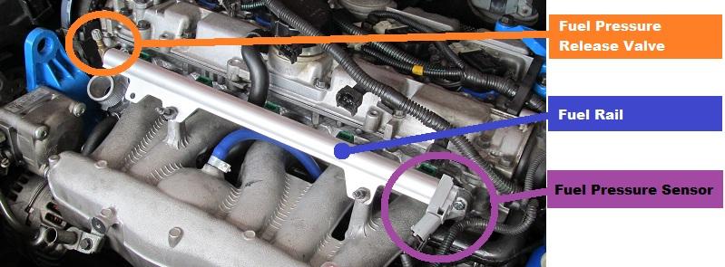
Place shop rag over fuel pressure release valve at end of fuel rail.
Press center of valve to release fuel into shop rag. It's only an ounce or two of fuel, the shop rag can more than handle it.
Remove the two bolts holding the fuel rail, iirc, 12mm or 10mm socket.
At this point, the fuel rail is held by the fuel return pipe and the fuel injectors.
WARNING: more fuel is about to spill out of the rail through hole where return pipe plugs in. It's easiest to just remove the Fuel Pressure Sensor on the end first and capture all the fuel in the shop rag.
Press the release on the fuel return pipe and pull (wiggle) the fuel injectors out. The injectors are held into place by o-rings, so you're only pulling against a slight pressure.
Place screws in baggie and tape to fuel rail. Put fuel rail on shelf.
(optional) you can easily disassemble the fuel rail, replace the o-rings (2 per injector), and/or replace the Fuel Pressure Sensor. Or even upgrade injectors and/or fuel rail at this point.
P107 Draining Radiator
Radiator drain plug is on driver's side under radiator corner facing downwards.
Use 13mm deep socket to open plug and drain fluid into bucket.
P108 Intercooler to Throttle Body air pipe removal (picture with arrows)
Disconnect electrical plug from pipe. I believe this is an inlet air temperature sensor but not sure.
Clamps on either end are worm type. Loosen intercooler side first then throttle body side, but it doesn't matter.
Remove air pipe and plug intercooler side with shop rag.
Clean pipe and store to side. Or replace with aftermarket one (Ipd just released theirs).
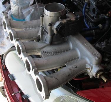
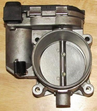
P109 Throttle Body(TB) removal
TB is underneath the Intake Manifold, held by 4 long bolts.
This is the underside of the manifold, so you can see what you are unbolting, before and after TB is installed.
Use a medium extension and 10mm (I think) socket.
After the TB comes loose, disconnect the electrical plug. Wire bundle only has a few inches of play.
Recover the gasket between TB and intake manifold.
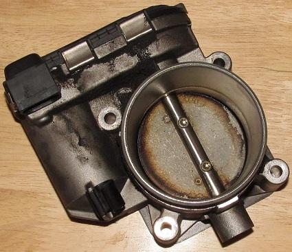
Clean Throttle Body using TB cleaner and brushes. Youtube for instructions, plenty out there.
BEFORE / AFTER
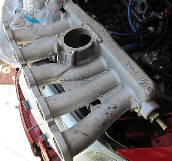
P110 Intake Manifold removal
Tape and mark the end of each connection to the intake manifold.
Remove each. Single-use clamps just insert a flat-blade screwdriver and twist to loosen it, then pry loose end till it disengages. If you're going to replace vacuum hoses, slice them off with Exacto blade, keeping the marked label on the hose.
Remove oil dipstick mounting bolt. You can remove dipstick now (see P111) or in a few minutes.
Loosen the Banjo bolt underneath front left corner of the intake manifold.
The Intake Manifold is held on by 6 bolts. The 3 on top must be removed. The 3 on bottom only need to be loosened! The manifold slides up/down on those 3 lower bolts. (insert picture)
P111 Oil Dipstick
Dipstick is held in place by an O-ring, it just pops out by pulling and wiggling.
New O-ring is included in the PCV Breather System Kit from IPD.
(optional if reusing intake manifold gasket)
P121 Accessories (insert belt diagram, routing suggestion, tensioning procedure)
Locate T55 socket on tensioner pulley facing passenger side of accessories mount bracket.
Attach T55 to long breaker bar and pull towards front of car to release accessories belt. Slip it off.
P122 Power Steering Pump
Remove bolts and move power steering pump to the side.
Replace bolts or put them into plastic bag and mark.
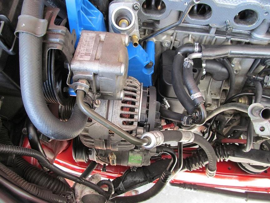
P123 Alternator removal
Remove alternator bolts. Bag and mark them.
Remove alternator. If it is sufficiently fouled, clean as follows:
Use Gunk gel thoroughly on alternator, hose down with water to rinse.
Use isopropyl alcohol to remove ALL the water, then air dry to evaporate the alcohol.
P124 A/C Compressor
Remove bolts and move A/C Compressor to the side.
Replace bolts or put them into plastic bag and mark.
P125 Accessories Mount removal
Remove the 7 bolts (3 long upper, 4 shorter lower), bag and mark these.
Remove accessories mount.
Remove the tensioner pulley (2 bolts, use same plastic bag) from the mount.
Gunk, clean, and/or paint it and let dry.
Do NOT degrease or paint the tensioner pulley. Clean the mount careful not to remove the lube grease.
P126 Thermostat Housing removal
Upper and lower Torx(30?) from thermostat housing.
Save the metal gasket on the manifold to thermostat housing, you will use it again.
Volvo sells thermostat and housing as a unit, about $80. You will re-use the metal gasket on manifold.
Consider replacing the lower bolt (or both) with a hex bolt of same threading.
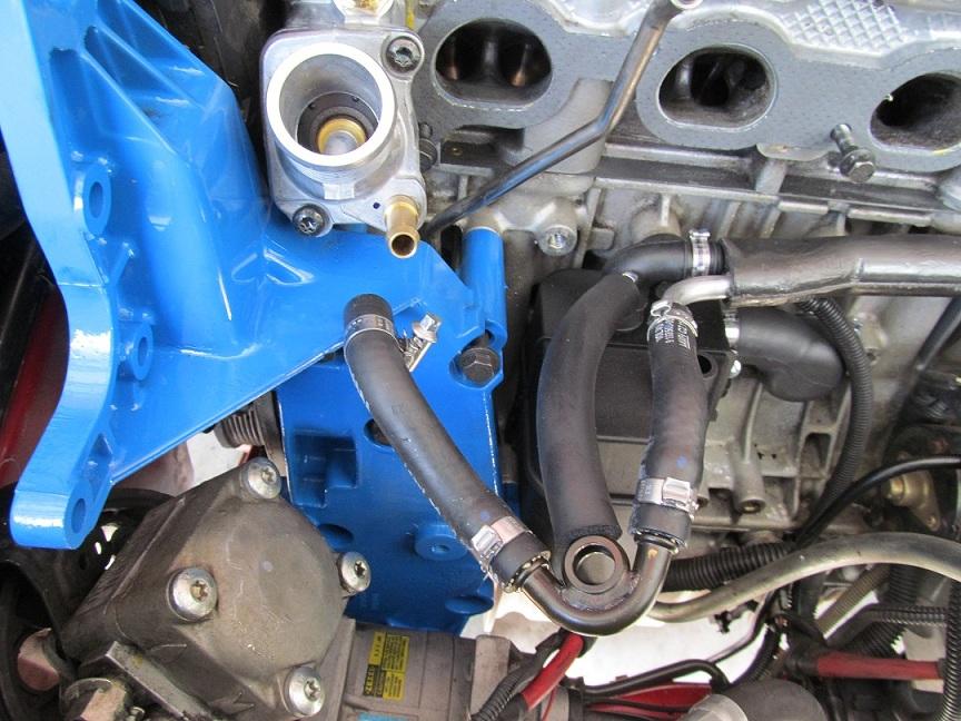
P141 PCV Breather Box removal
Using flathead screwdriver, destroy and remove the single-use clamps for the two connections on top of the PCV Breather Box.
Remove the pipes and hoses from the box.
Remove the two bolts holding the box to the engine block, store bolts in the mounting holes on the engine.
Clean the area as needed.
P151 Stock Air Box/Filter/MAF removal
Loosen the 4 screws on stock air box cover, remove cover.
Either bag the screws or place tape over each, store cover and screws.
Remove air filter, inspect and clean or replace as needed.
Remove the 2 screws holding air inlet to air box and slip air inlet off airbox.
Remove electronic plug from topside of MAF, release clip should be on port side.
Loosen worm clamp on MAF to turbo inlet pipe.
Remove the 3 airbox mounting bolts and bag them.
Remove airbox by wiggling MAF end out of turbo inlet pipe.
P152 Air Inlet removal
Remove the 3 bolts holding the air inlet in place.
Slide the air inlet loose and bag the 3 bolts, tape it to inlet.
P154 Upper Engine Mount removal
Remove the 4 bolts holding the upper engine mount.
Note the location of the 2 longer bolts vs. the 2 shorter bolts.
Bag the bolts, remove the mount, clean and paint it (required
 )!
)! P155 Radiator hose removal
Loosen clamp and slip hose off pipe.
Reposition hose to be out of the area.
(optional) Or remove it entirely especially if replacing with silicone hoses.
P156 Turbo Inlet Pipe removal
P157 PCV pipe removal
Use a flathead screwdriver to destroy the single-use clamps on each end of PCV air pipe.
(side options: Turbo Control Valve, Vacuum hoses, Turbo Inlet Pipe replacement)
Maintenance and Consumables list:
Rubber gloves, paper towels, hand cleaner, shop rags, degreasing area + water hose
Gunk (foam and gel), Awesome Orange, Isopropyl Alcohol, large bucket, hazardous material trash bag
3M gasket sealer and adhesive
Oil Change (recommended)
Vacuum hosing: (recommended) 5mm and 6mm inner diameter -- about 7 feet of each
Spark Plugs (optional)
Ignition Coils (optional)
Wire Harnesses (optional)
Tips:
Bolts storage: when removing bolts, immediately place them into plastic bags and mark the bag with permanent marker indicating component to which they belong, or bolts can often be stored back in the holes they came out of.
Learn the vacuum system before you begin cutting and replacing. There are two check valves that you must remember the arrow direction (towards turbo). (Tiny) vacuum diagram is on hood lower right corner.
Wire and plugs management: clip the zip ties and move wire bundles safely out of the way. measure run lengths and replace any damaged wire harness. plugs are dummy-proof, you cannot install plugs in wrong place or orientation.
Tools list:
Torque Wrench
Breaker Bar (for accessories tensioner)
Torx metric kit (8mm to 60mm NAPA, $36)
Ratchet & socket kit, with short, medium, and long extensions
Wrenches (including a 7mm for hard-to-get worm clamps if stubby flathead can't get to it)
Needlenose Pliers (for reusable vacuum hose clamps)
Screwdriver kit, especially flatheads and stubby
Exacto Blade
Wire Ties
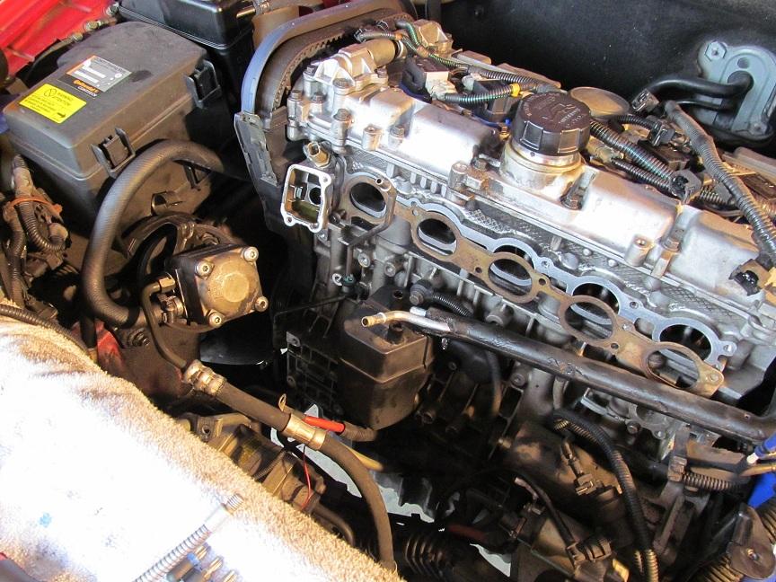
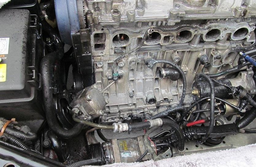
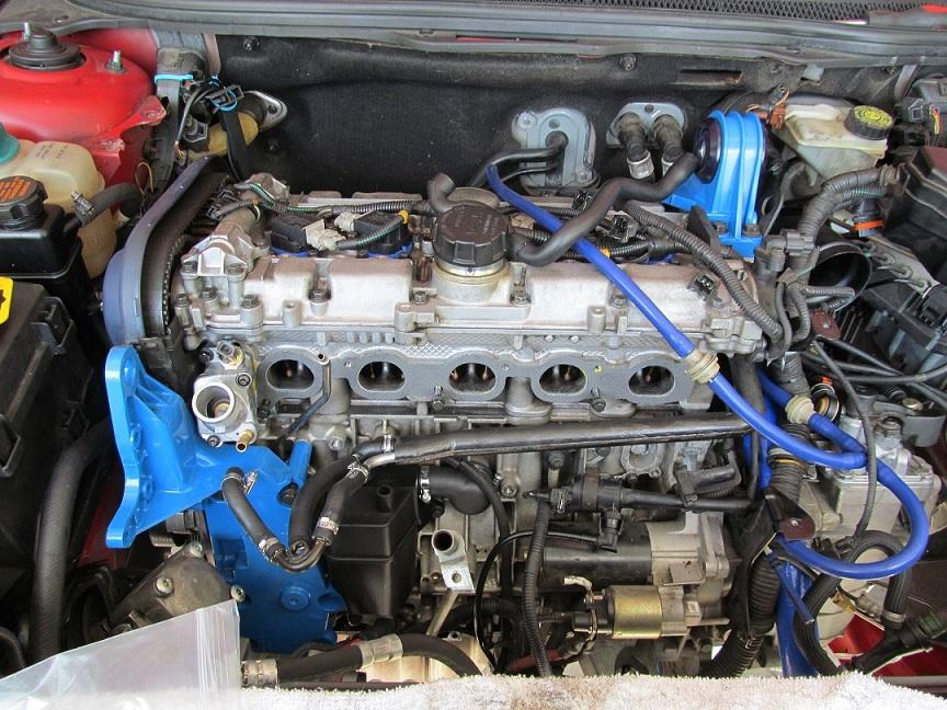
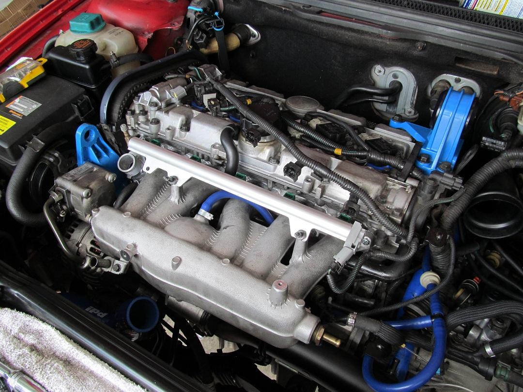
WASHING THE ENGINE !! YES WASHING ...
See the above picture and the one just below.
After covering the this side of the engine with GUNK GEL and letting sit for 20-30 minutes, I sprayed it all down with a garden hose on JET setting and used a couple different brushes to get the hard stuff loose. DO NOT WORRY if water gets in your valves. Mine were full (except the #4 open valve, the water went down into the oil pan) .. just finish cleaning then soak up the water above the closed valves with paper towels. Then after you get everything put together, and run the car for 5-10 minutes (DO NOT DRIVE ANYWHERE) ... CHANGE YOUR OIL AND FILTER ... or your oil will foam up with the water in it.
Let's stop all the paranoia about water on the engine. They're not fragile. They won't melt when wet. That's the Wicked Witch of the West. Electronics just be careful, but you're simply washing away the water with alcohol and then letting the alcohol evaporate. You should still avoid the ECU and fuse box, but just because they're closed and you don't want standing water in there.
Replacement and Reassembly
7-22-2012
Hi, yes, I did do optional stuff, and I have stated this repeatedly. But as long as I had all this apart, it was within reason to clean things up. Regarding cleaning electronics (alternator), what technical reason do you give for not cleaning it with water and then alcohol? I've been around electronics all my life and never ruined anything by cleaning it when power was not attached and capacitors are fully discharged. Isopropyl Alcohol is cheap and an incredible solvent. Plus it removes all the water and evaporates quickly.
When I did the PCV kit, I didn't know the quickest way to do it. There WAS NO guide, even the Vida/Web version was weakly described, but it did say remove the power steering pump etc. I initially did NOT take that approach, trying to go instead through the top, fuel rail -> intake manifold -> pcv box. But I quickly found the bottom-left bolt on the pcv box required removal of the accessories bracket. One person said they were able to remove the bolt without removing the accessories bracket, but they said that after I had asked for weeks, and after I had completed my job. At least with my guide now, you can choose what you want to and not want to do, even if you've never done it.