You must be logged in to rate content!
9 minute read
The DIY led gauge cluster thread
Compliments of fueled by hate @ www.zilvia.net
This thread is to show people how I did mine so they can copy if desired.
To start off here is another guy who did his, but the design of the cluster is a little different, but still another source for info.
Tools needed:
soldering iron
hot glue gun
wire (I used wire from a junk wiring harness)
extra battery or power source for testing
screwdriver
wire cutters and/or strippers
leds
printed circuit board (pcb)
voltage regulator lm317t and heat sink
resistors and capacitors
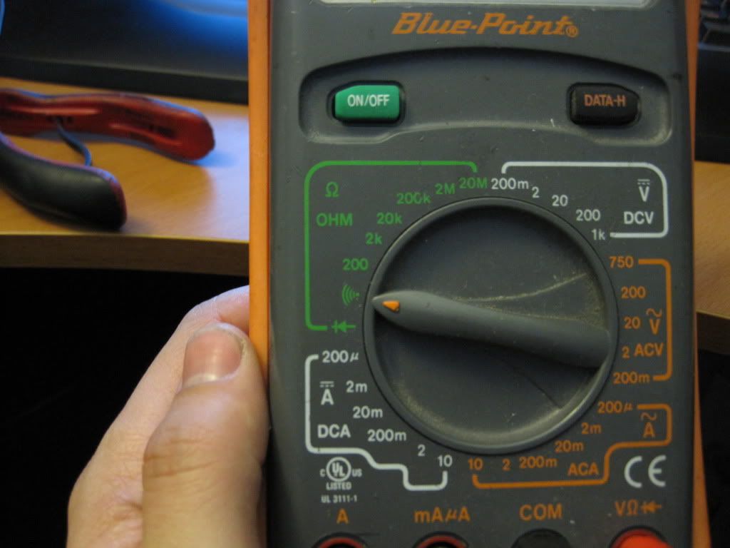
DMM
thermal paste
Note: You can buy the pcbs, resistors and capacitors in bulk off ebay and pay less than or equal to that of radio shack and get 10 times the quantity. Just make sure you buy from U.S. sellers so you don't wait a month for shipping from China.
The leds I'm using are superflux style. I used Nichia white leds that can be ordered from their U.S. vendor. Part number isNSPWR70CS-K1
General Lighting/Lamp type LED
The red leds are actually red-orange, but look very red. They are lumileds part number I used is hpwt-dh00.
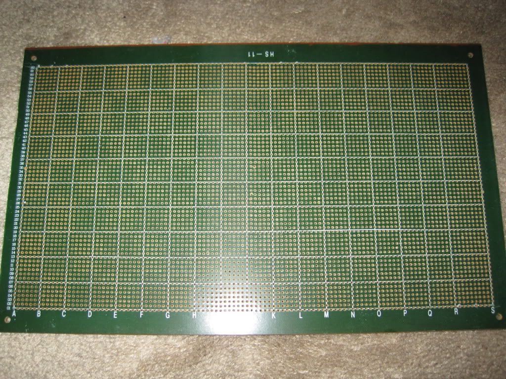
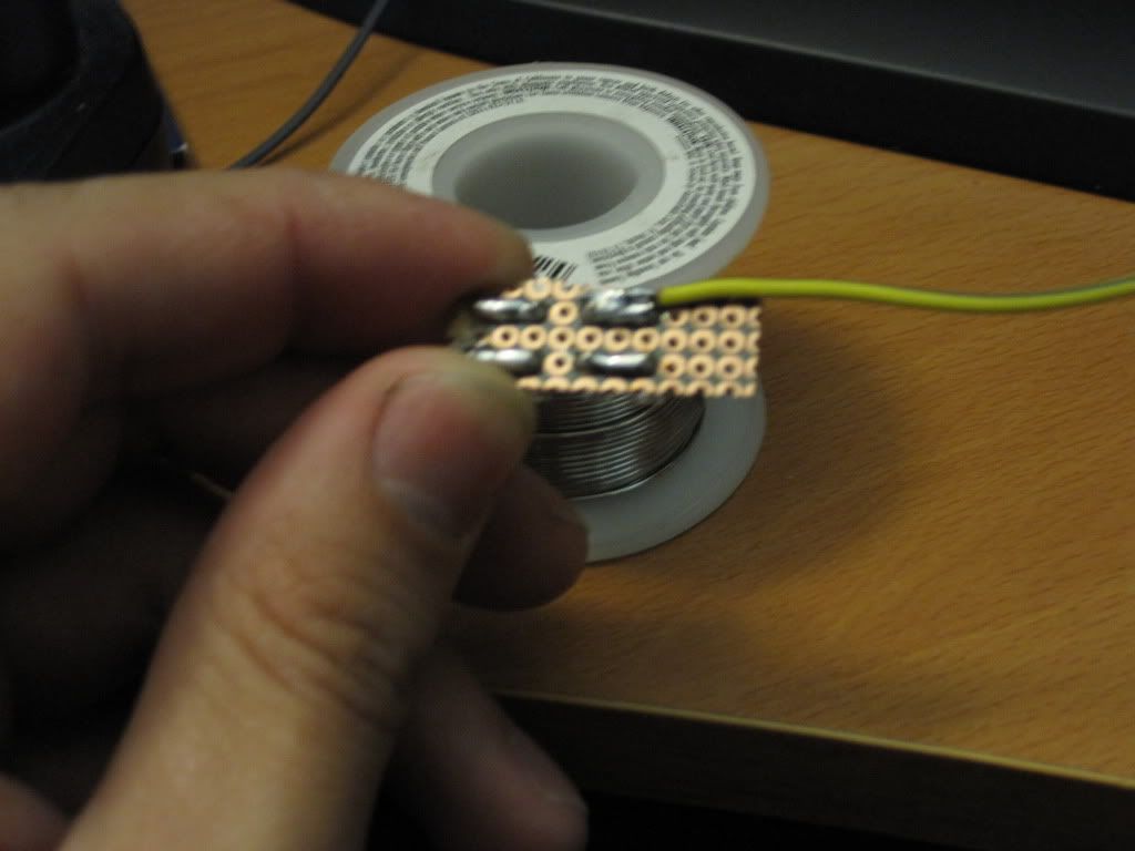
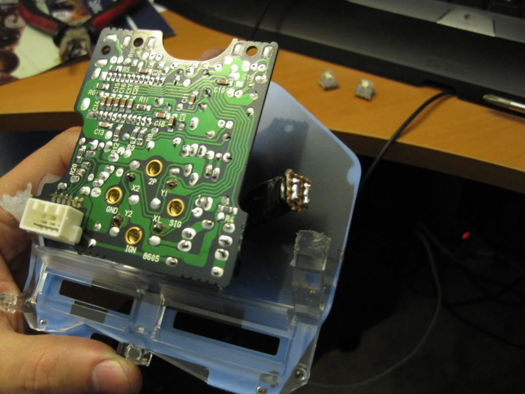
To use these leds you need to buy a pcb like this with the small copper contacts on one side.
Grid-Style PC Board with 2200 Holes - RadioShack.com
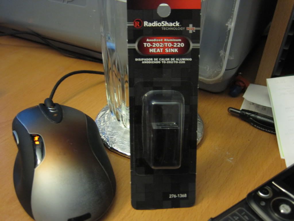
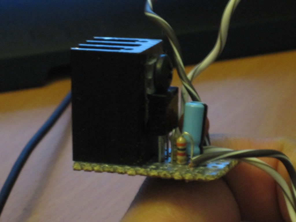
You will need a voltage regulator and heat sink.
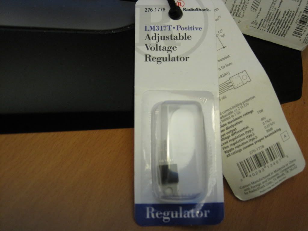
Adding this will maintain a constant voltage to your leds no matter if the car is on or off.
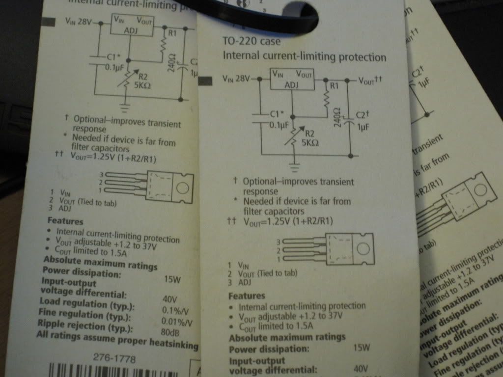
First thing you need to do is measure the voltage on your car battery while the car is off. The lm317 will only work when the output voltage is 1.5 volts greater than the input voltage. This means that if your car battery tests 12.5 volts you need to set the lm317 for less than 11 volts. I set mine at 10.87 volts and used a 390 ohm and 3000 ohm resistor. To calculate the voltage you want use this site.
Once you figure out the output voltage you want order your resistors and capacitors that you need. Next you need to get the specs on your leds and use this calculator to figure out what resistors you need for them.
LED series parallel array wizard
Your source voltage will be the output voltage from the lm317. The diode voltage forward will be the voltage your leds runs at. The current will be the milliamps (ma) your leds run at. Then enter the number of leds. I ran the Nichias at 3.1v at 50ma and ran two in a series. I ran the lumileds at 2.67v at 70ma 3 in a series. Once you figure out all your specs order the resistors you need for your leds.
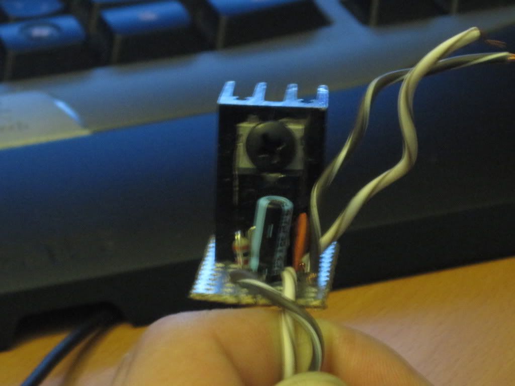
Finished lm317 board should look something like this.
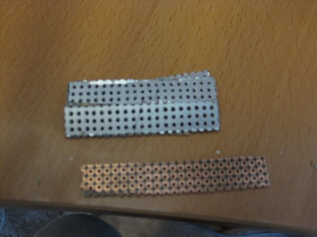
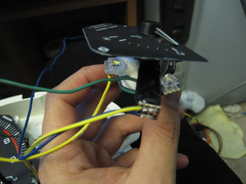
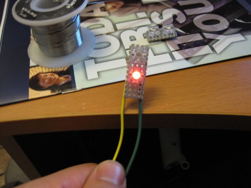
Next I cut up the board and started soldering the leds on to little squares. Don't solder the led legs for too long or you'll bur them up or shorten their life span. Easiest way to cut up the board is to score it a few times with a razor blade then use cutters. You can also spray the boards any color you want.
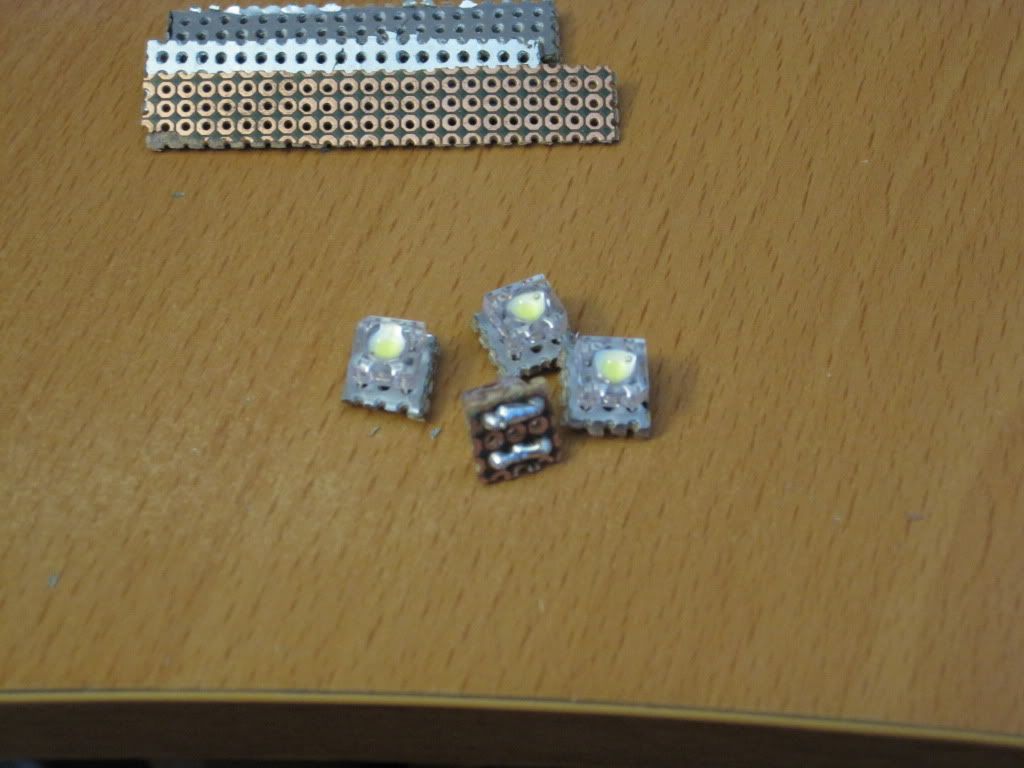
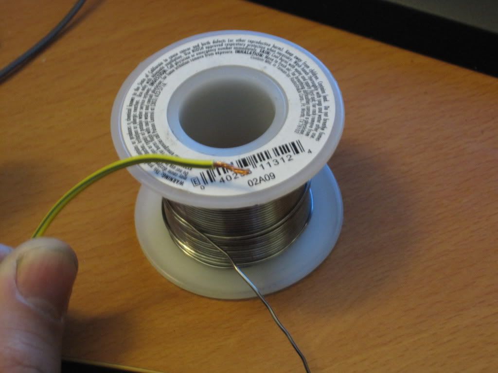
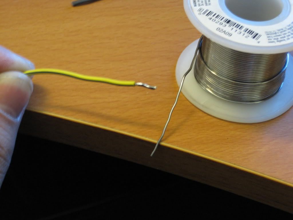
Easiest way to connect wires is to strip a small piece off, then put solder on the wire, then solder it to the led. You want a decent amount of solder on the board because it acts as a heat sink for the led.
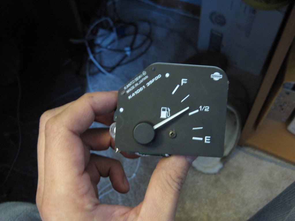
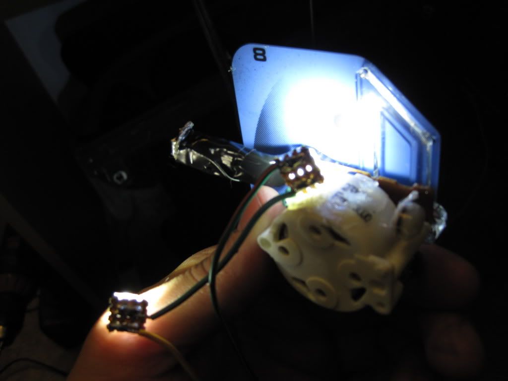
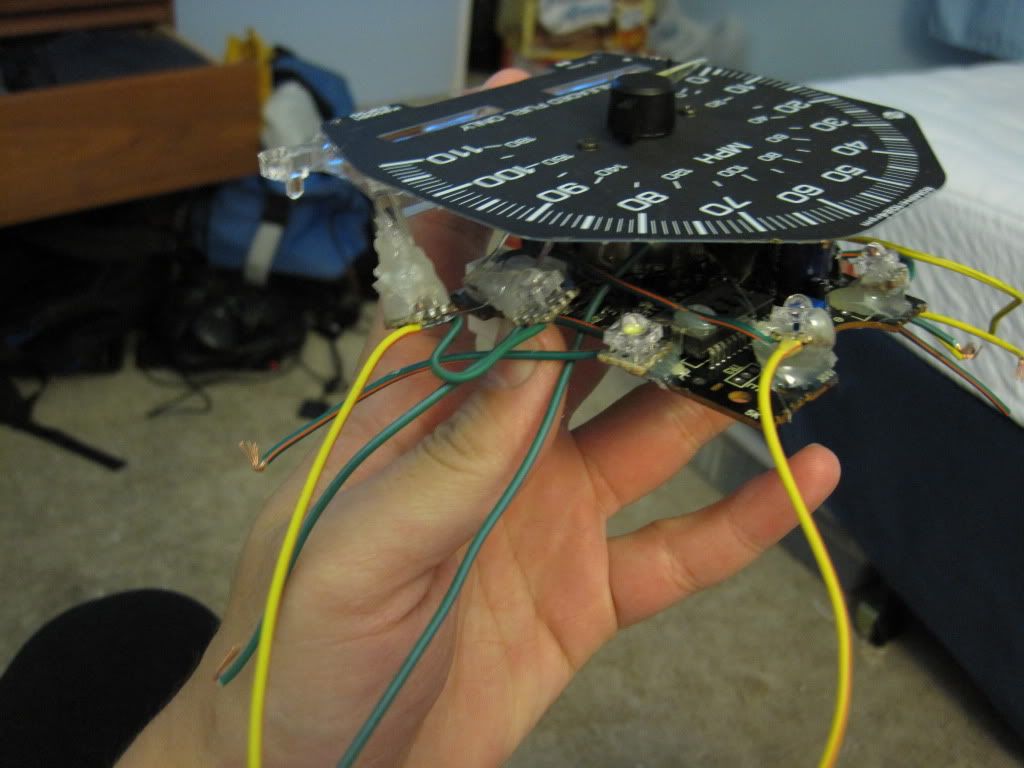
Remove your gauge cluster and remove each individual gauge. Each gauge has clear plastic rods that light travels through to light up the needle.
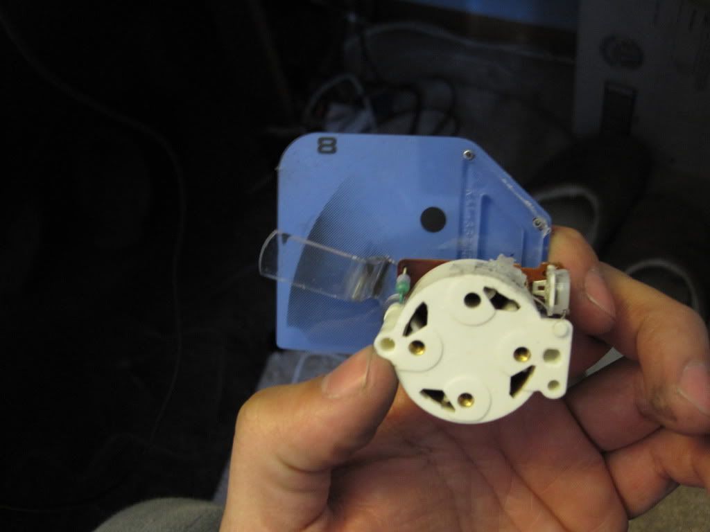
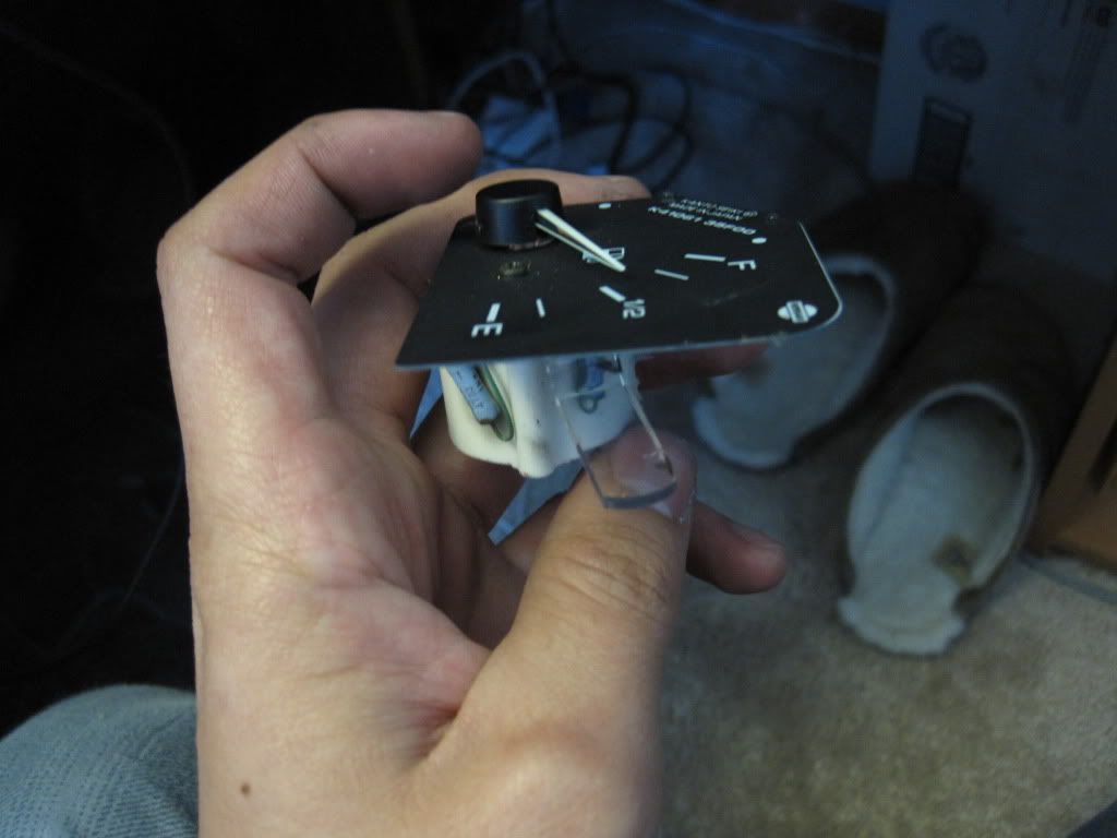
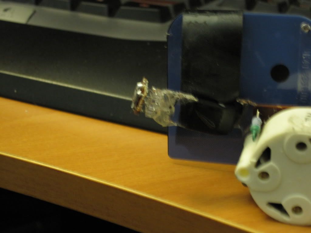
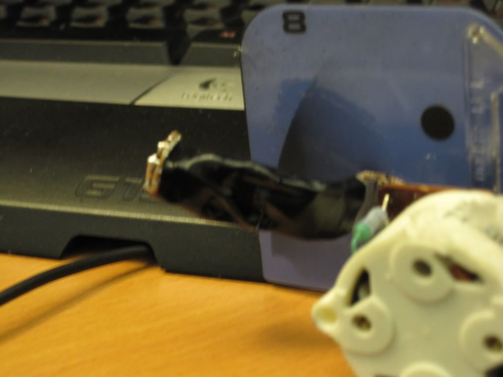
What I did was hot glue my red-orange led to the end of each then wrap it with black electrical tape to prevent the red from bleeding through.
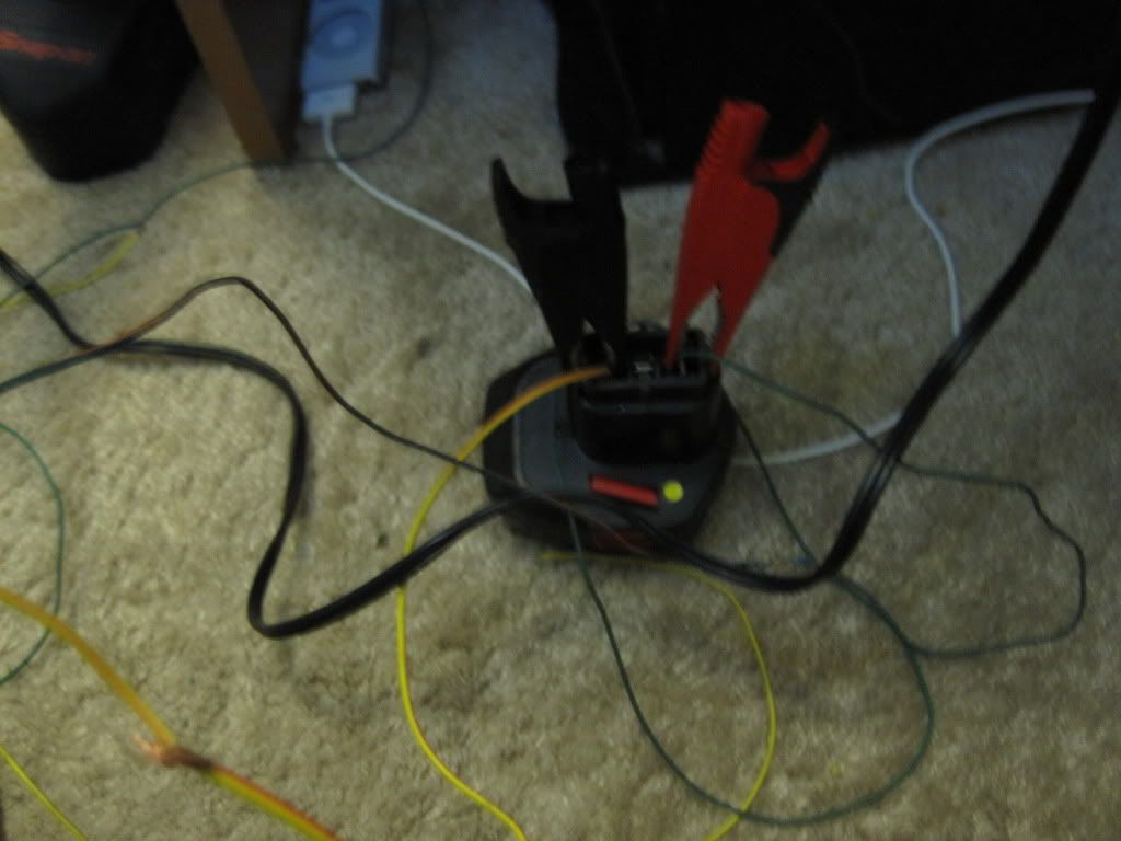
Next start aiming the white leds then gluing them in place once satisfied. I used my drill battery that was drained slightly below the output voltage I needed.
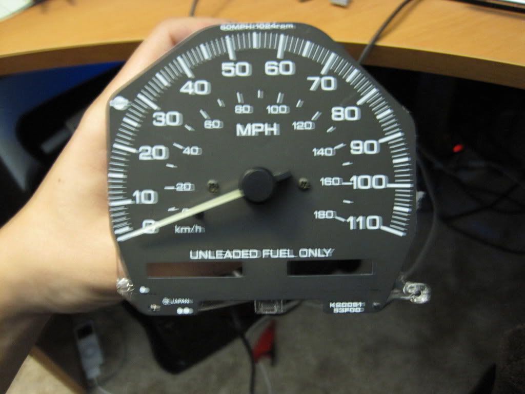
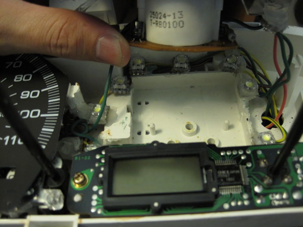
The mph gauge is a little harder to do but is relatively the same idea. There are plastic rods that aim down that throw light on the odometer that you will need to glue some white leds to like the needles. You don't have to wrap them in tape because you want the light to bleed out.
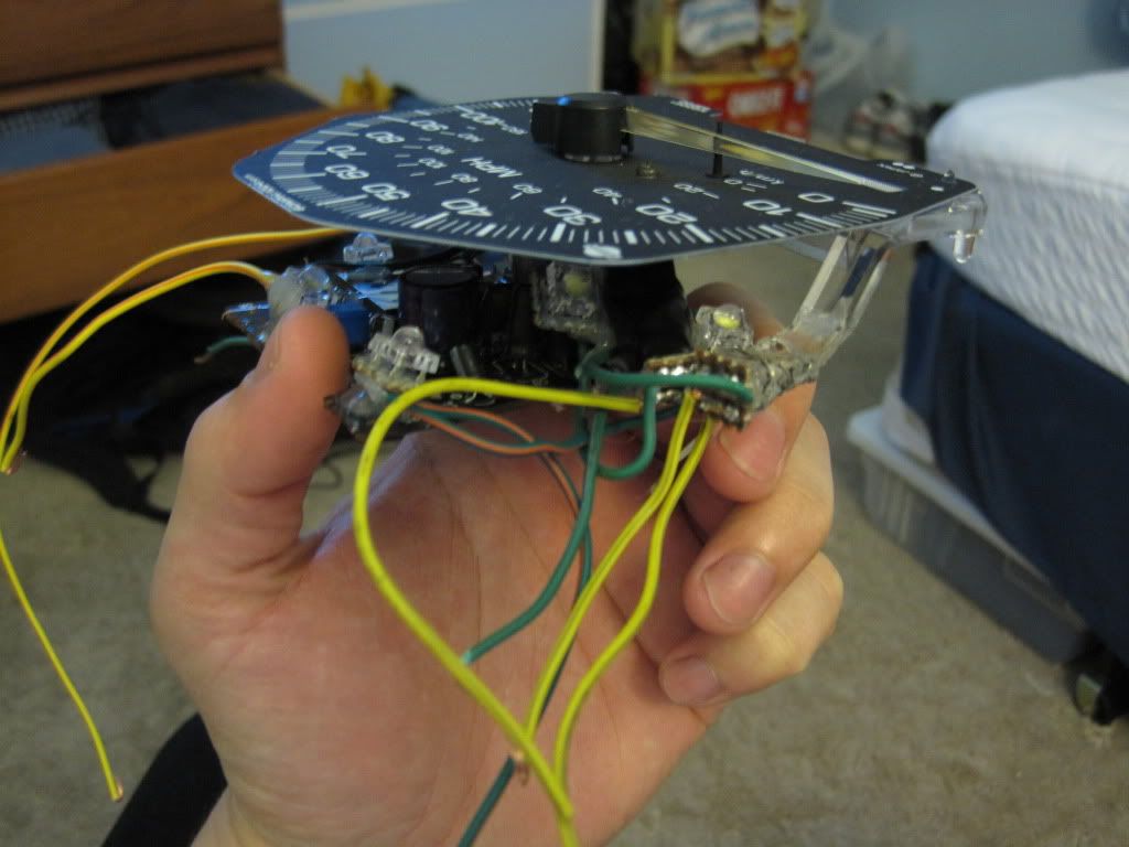
The tach is a little easier to do since there is room to glue the leds to the cluster.
Do the last gauge and you're almost done.
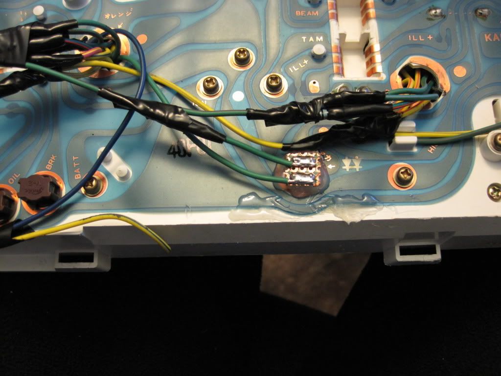
Next wire everything up.
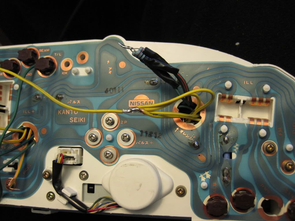
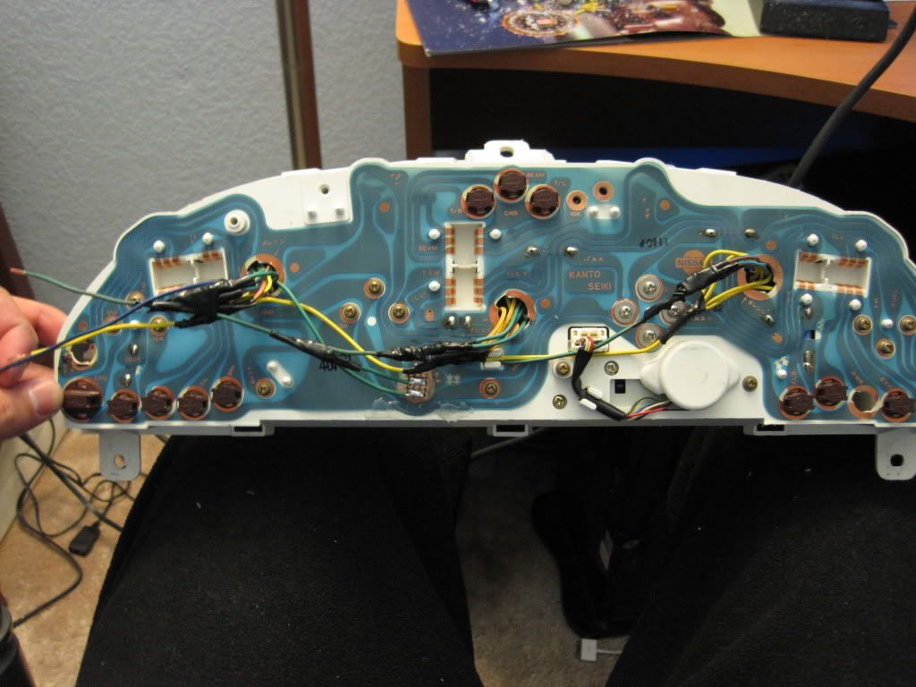
If you forget the polarity of an led while wiring everything up you can use a dmm in resistance mode to dimly light it up. This works well for the red leds, but not as much for the white because it requires a higher voltage.
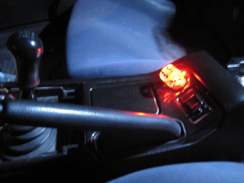
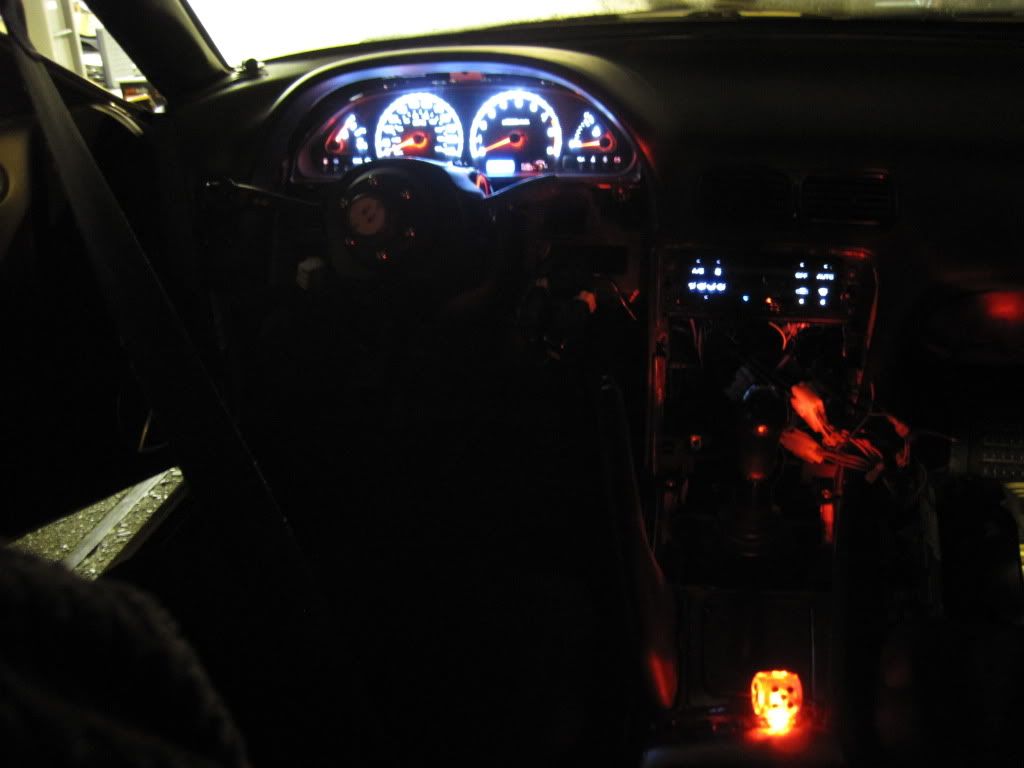
Also, the bulb for the clock is on the same circuit as the cluster lights so you need to replace it with an led.
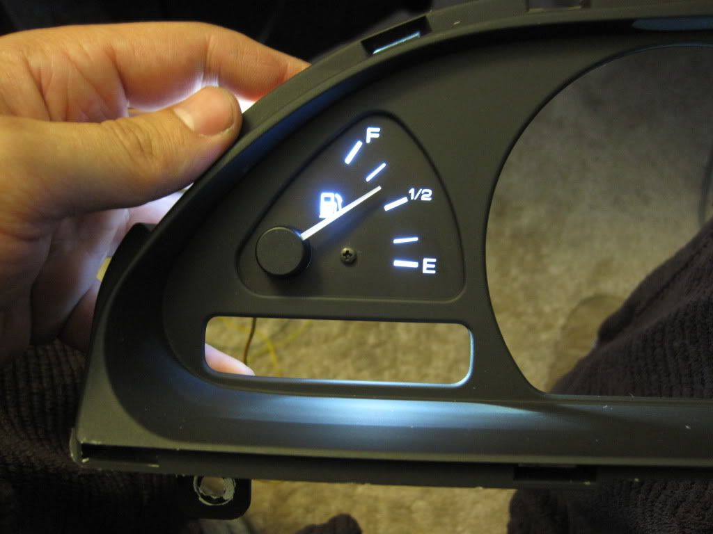
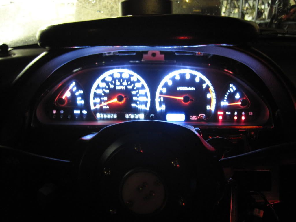
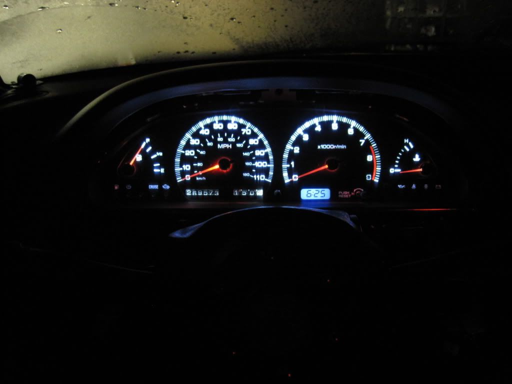
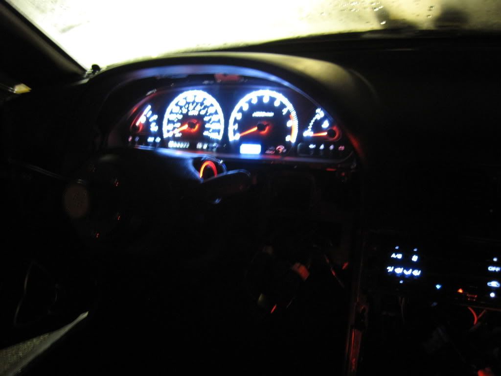
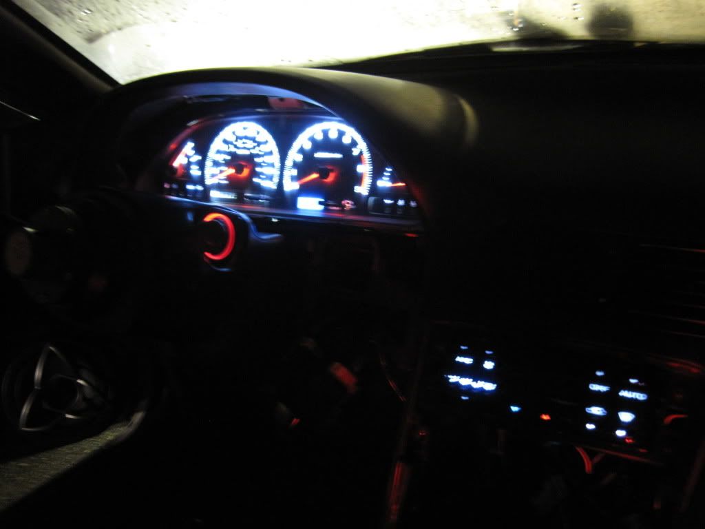
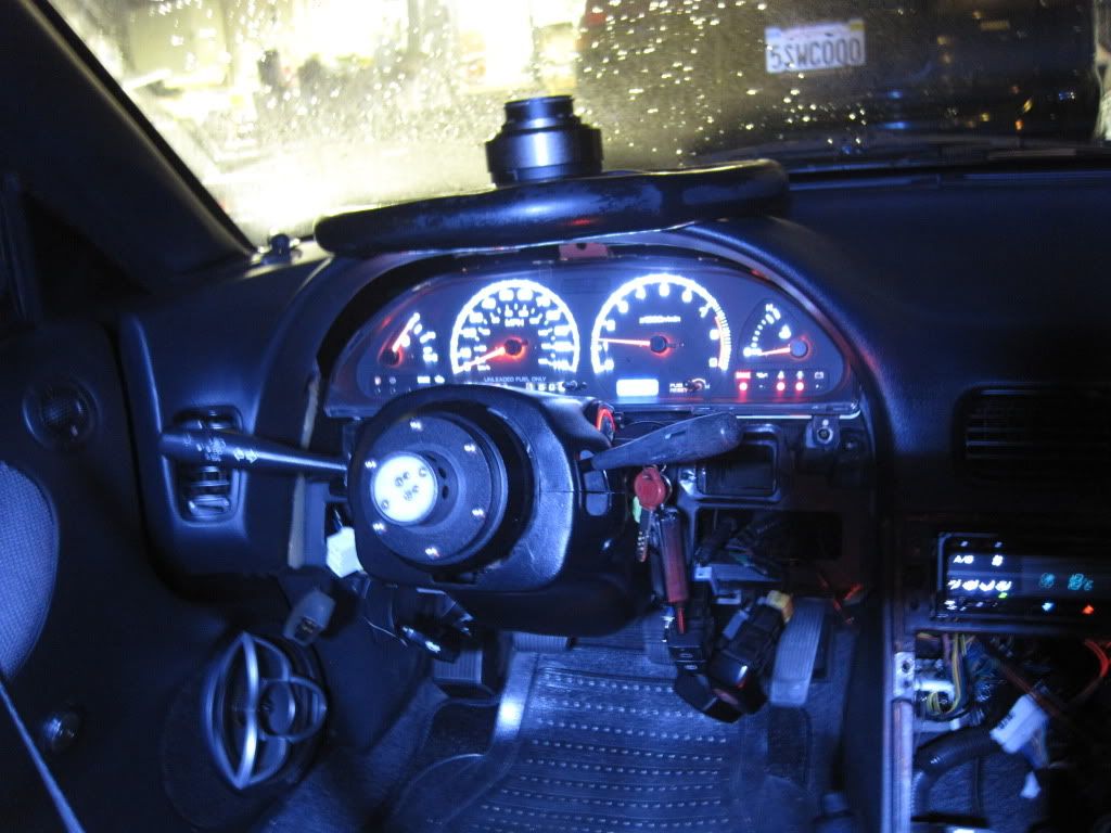
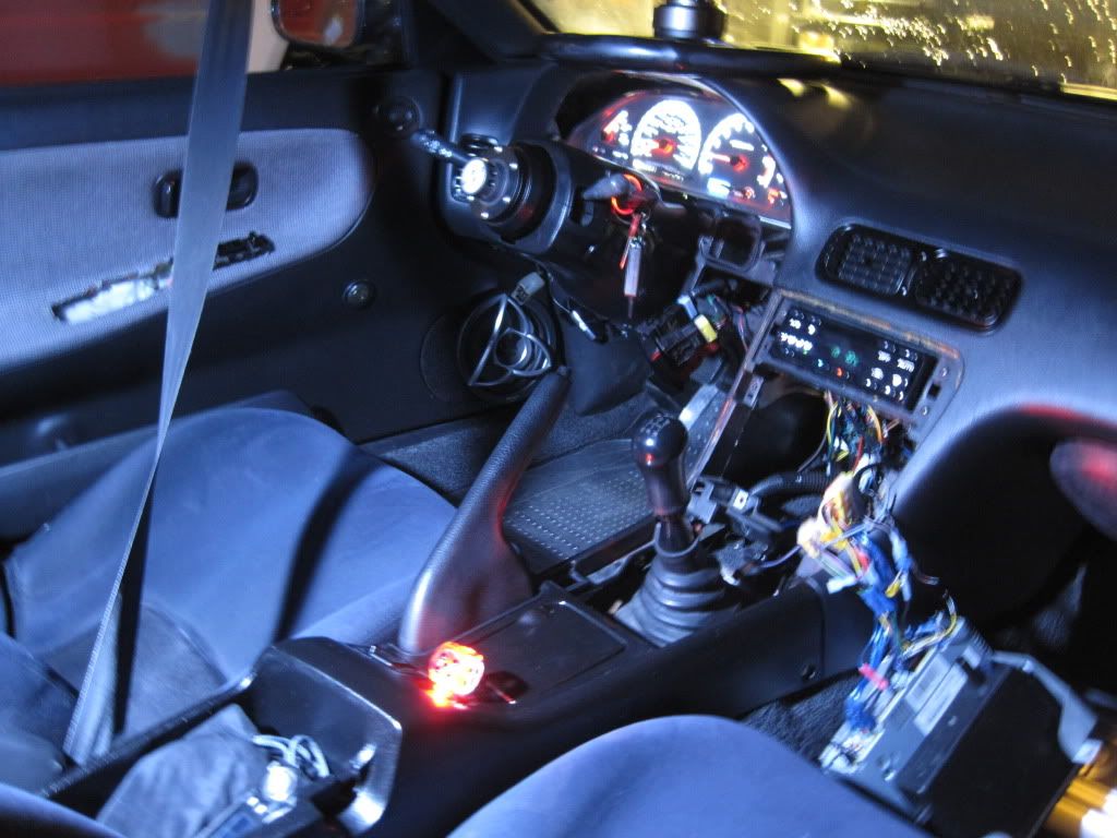
Here is the cluster installed. I am a camera noob and don't know all the settings.
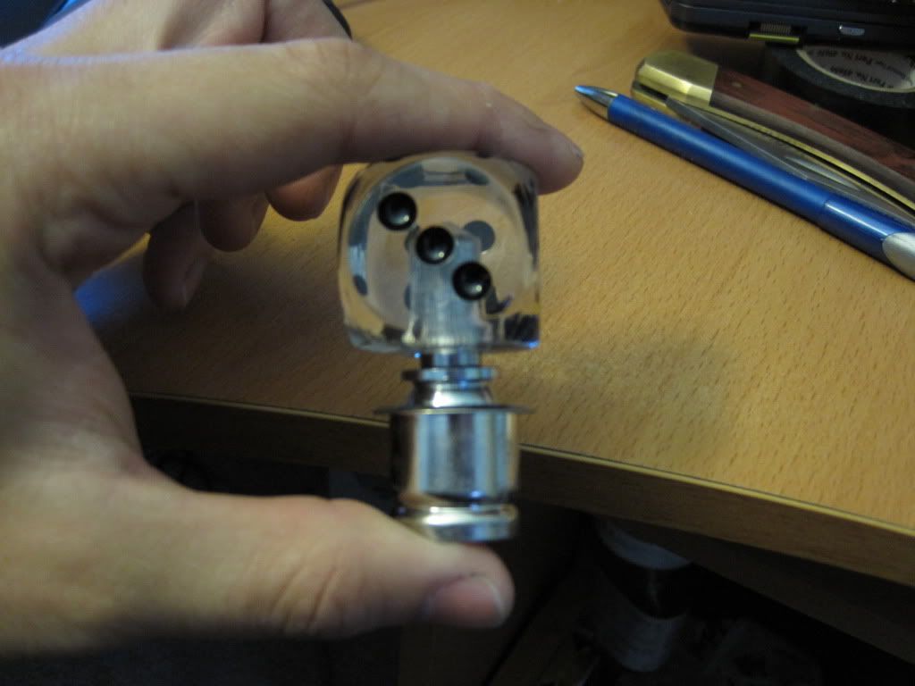
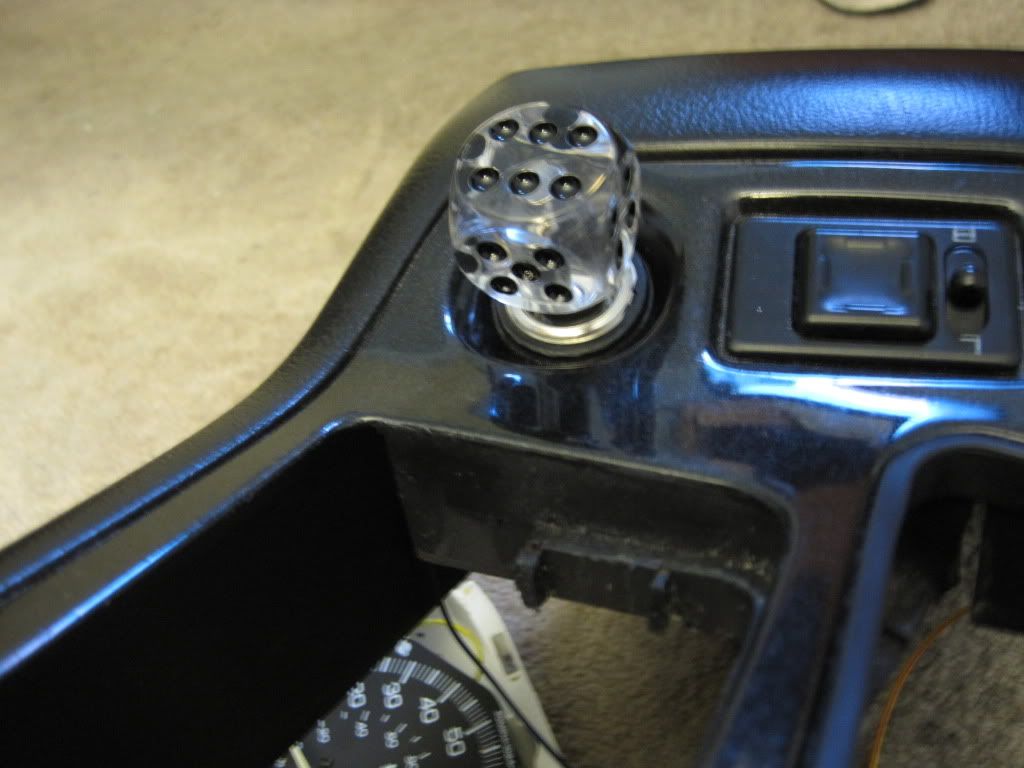
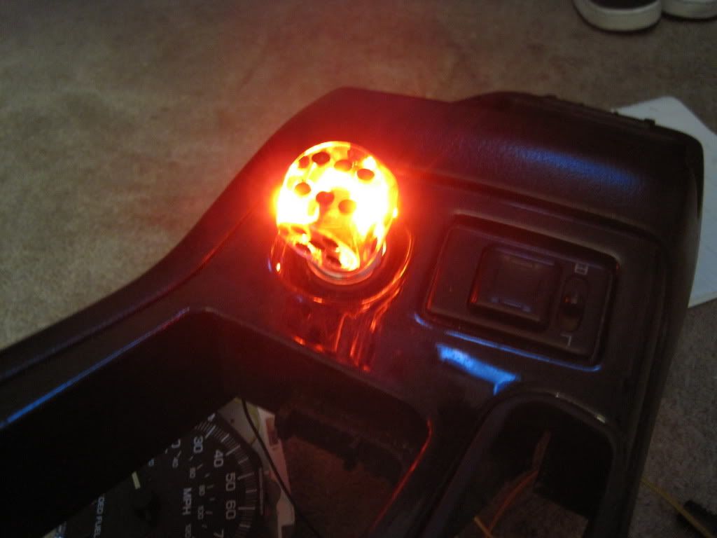
Also I bought this from auto zone and shortened it for a quick side project.

This is great ?
Posted by Diggymart on 2/10/20 @ 6:35:16 PM