You must be logged in to rate content!
28 minute read
VF Eng. Ver 3 Supercharger Install
Compliments of Doug996inKC @ www.6speedonline.com
Hi guys.
Over the winter, I'm going to be installing VF Engineering's version 3 supercharger in my home garage. It's definitely going to take "all" winter, as I plan to take it slow, have fun, and make as few mistakes as possible.
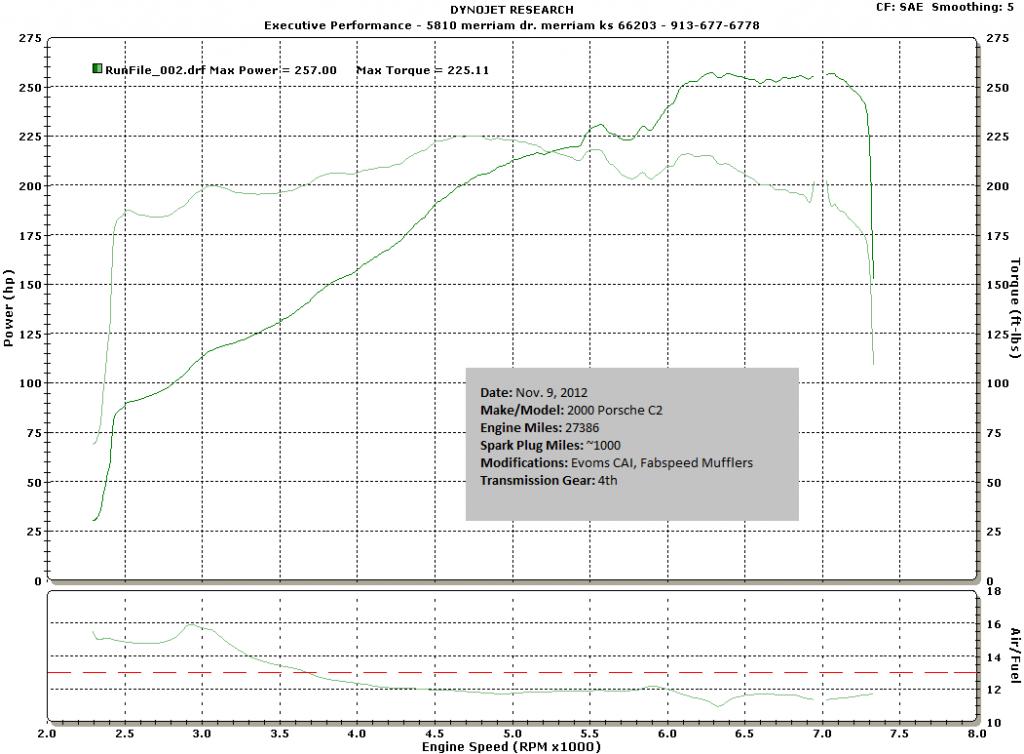
The neat thing about this car (if I may toot my horn a little), is it has a history in the 996 world. Back in the day, it was owned by Todd Zuccone's shop Evolution motorsports, and, from what I've been told, was a test car for some of VF's first supercharger prototypes. Call it fate that she's getting a V3 so many years later. I'm not sure when, but Todd told me the factory motor was replaced with a remanufactured 3.4L motor at about 30k miles. The car currently has 59k miles. Whether or not the motor was run with a SC, I do not know. But, a dyno from November 2012 shows it is running strong with almost 30k on the reman.
I've gained a lot of valuable knowledge from reading Aaron & Stacey's threads (from a few years ago), so I shouldn't run into any problems...  . I'm just going to keep telling myself that.
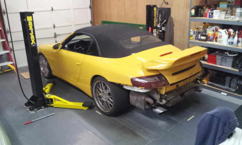
Two weekends ago I resolved my self-botched MaxJax install.
http://doug996inkc.blogspot.com/2012_12_01_archive.html
So let's get started!
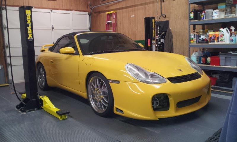
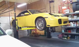
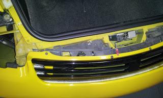
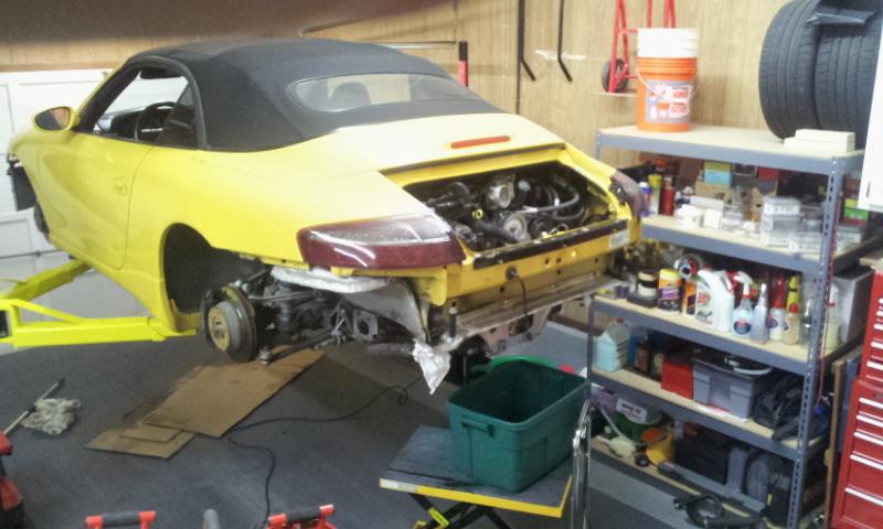
The subject:
Tear-Down Part #1
The owner and friend of mine of http://rennsportkc.com/ has installed 100+ of these kits. His advice is to start with the cooling.
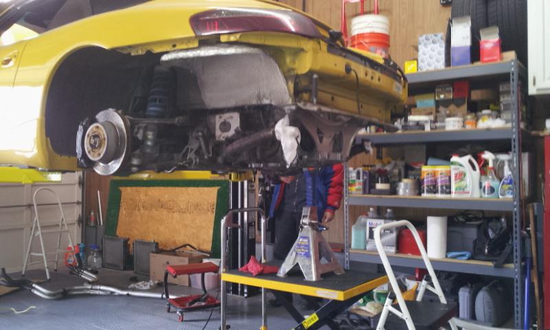
Up on the lift.
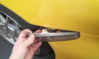
Popping out the clear side markers.
Aftermarket fiberglass front bumper, as evident by the chip near the screw. 
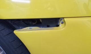
Headlight removal.
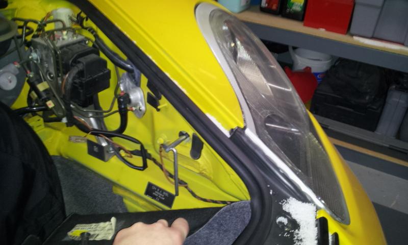
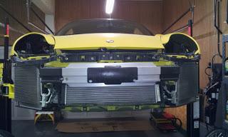
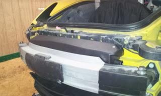
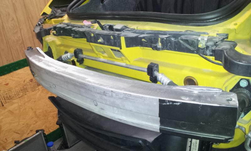
Front bumper removal.
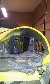
Fender liner removal (need access to the coolant hoses).
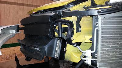
A few more screws to remove, here and there, and the bumper is off. I installed the center radiator several years ago. For the SC kit, it will need to be disconnected from the engine cooling system and re-purposed as a self-contained air intake cooling system.
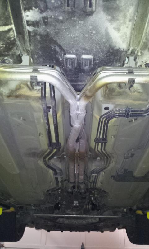
The underbody panels.
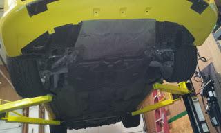
Underbody panels removed.
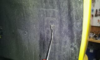
Historical marking made by EVOMS back in the day?
Hardline coolant hoses. The SC's coolant hoses will travel along the same path.
Tear-Down Part #2
Very little progress was made this week. Perhaps the thread title should change to "DIY... + all the other crap I decide to do along the way". 
For example, my list has grown to:
- replace motor mounts
- replace water pump
- replace all coolant hoses
- coolant refill (will use suction method for extraction and refill)
- new custom exhaust (headers to tips -- some crazy ideas, but may result in an unbearable sound)
- rear brake rotors & pads (rotors measured below min. thickness)
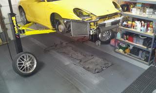
Most of the work will be performed on the rear of the car. Tools & workbench are steps away.
Won't need this EVOMS cold-air-intake any longer. Debating on whether to sell or not. What are these going for used these days?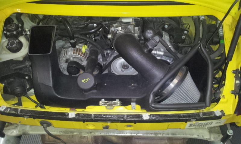
Removed O2 sensor electrical connection.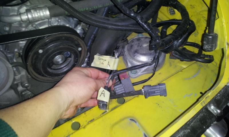
Remove drain coolant plug (will wait for a warmer winter day -- yeah, oxymoron) to remove hoses.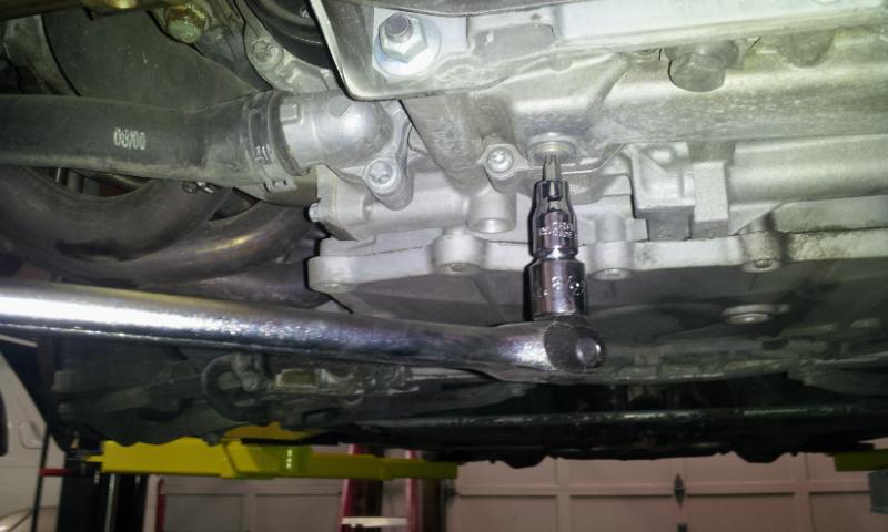
Coolant draining. Flash photo makes it appear clean, but it was very brown. At least I didn't notice any metal particles floating around.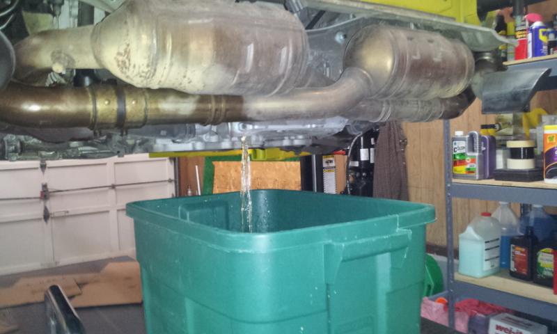
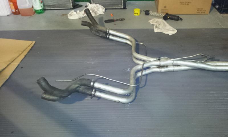
A few days earlier, sprayed a liberal amount of WD40 to nuts & bolts of the exhaust system. Removal was painless. Kept the headers fastened to heads (for now).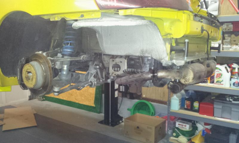
Fabspeed mufflers.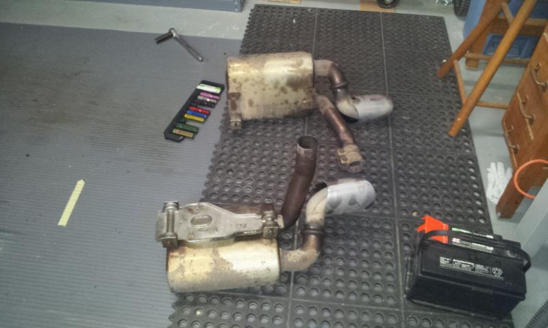
Catalytic converts removed too. Wow, this exhaust is heavy! With the extra 100 lbs. going onto the car, I'd like to find some weight shedding opportunities. And I think I've found that opportunity laying right here!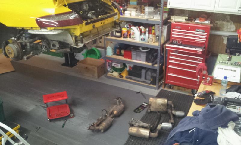
Radiators & Coolant Hoses Removal
So over the weekend, I found a few hours to remove the radiators and some of the coolant hoses.
Although it's not necessary to remove the side radiators, I found it much easier to remove the hose clamps (worm & OEM spring type) this way. Also, I'm making a best possible effort to drain/extract the original coolant, and flushing the radiators while off the car will be much easier.
I'm considering removing the two coolant Y-pipes (hard pipes) in order to remove their respective flexible hoses. Those clamps are in a really tight area! Another benefit to doing this is I could replace the fuel filter much easier, and.... (idea time), fastening plastic holders to the top of the pipe(s) to hold the SC coolant lines. Aaron, I remember you used zip ties? The goal was (and is) to prevent heat transfer from the aluminum coolant pipes to the braided, SC coolant. (Yes, I know this is ****. I know these lines are braided/insulated.)
Enough rambling, here are the related photos.
Removing 3rd radiator. Flush and disconnect OEM hoses.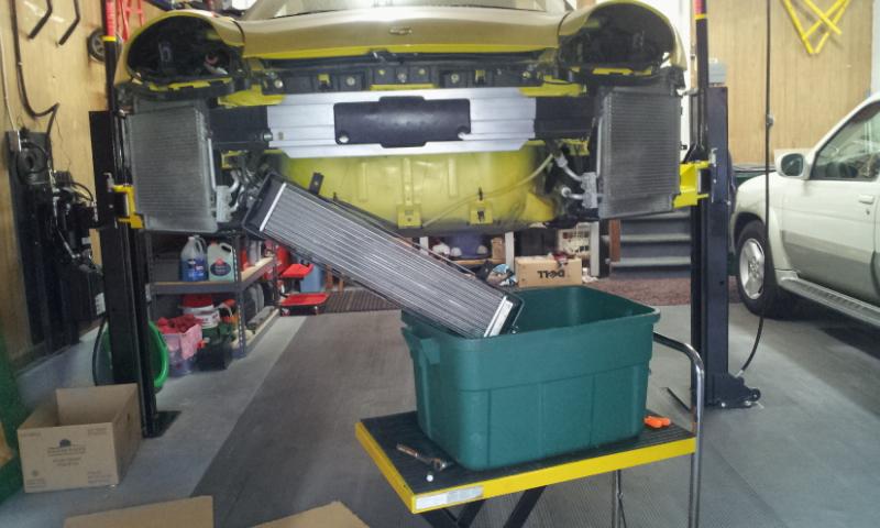
Passenger side radiator. The lower hose is "T"ed. The smaller connected the 3rd center radiator. The larger connected to the side radiator. I will be selling these hoses, along with the brand new center radiator that came with the SC kit. PM me if you have any interest.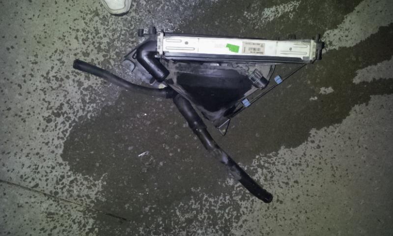
Passenger side, sans radiator.
Passenger side coolant hoses connected to aluminum Y-Pipe. That's a tight fit!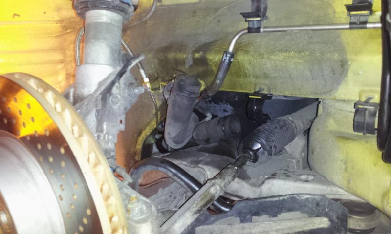
This Craftsman hose clamp compressing tool is a worthwhile investment.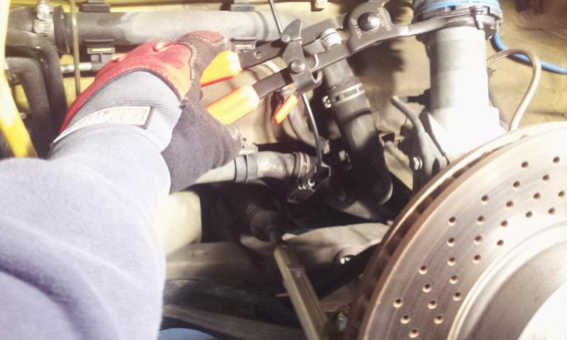
Driver side radiator.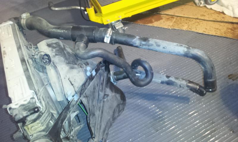
Driver side sans radiator.
Coolant hoses removed from engine block.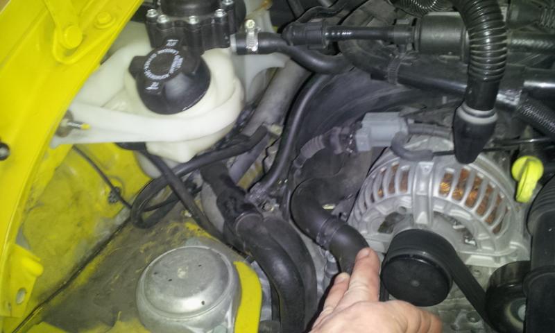
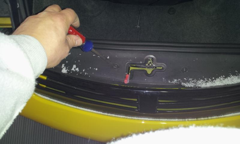
On the garaga ceiling are two, 8' long shop lights, hanging directly over the rear area of the car. The the engine lid open, the light is blocked. Off comes the engine lid/wing! Somebody once asked me in a PM how the Gemballa wing's brake light is connected. Here's the answer: brown (+), brown/black (-).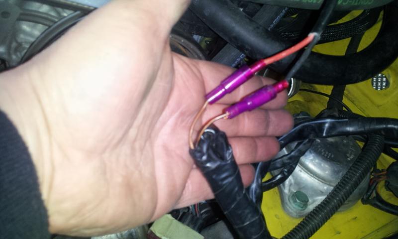
Marked the position (black line) of the wing.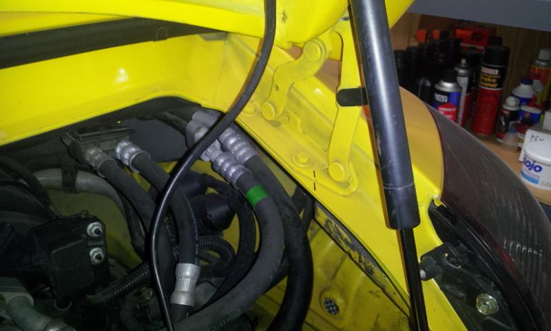
Ah, more light.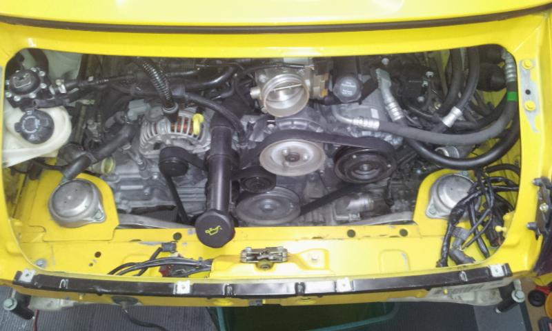
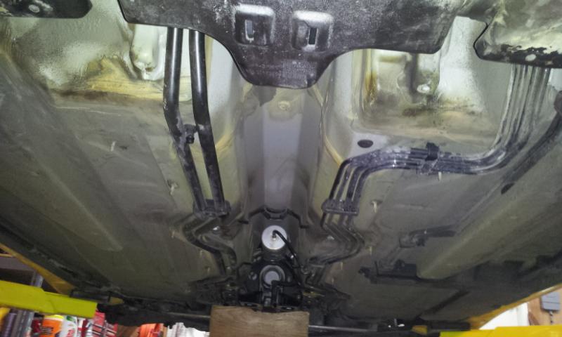
On another note, new coolant hoses, low temp thermostat, water pump, fuel filter, etc. are trickling in. Anybody have any ideas on what to use to suspend the hoses from underneath the body, but above the aluminum coolant pipes (see photo below). I have complete access to that tunnel now.
These are a PITA to remove.
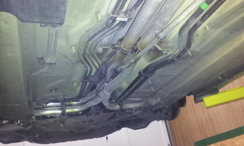
Ample room in the tunnel for a 2-wheel drive. I'm thinking of ways to suspend the SC coolant lines. Will replace that fuel filter tonight.
My plan is to keep this vehicle for at least 10 more years (by then, my daughter will be old enough to drive it). May as well replace these hoses now.
Pelican Parts is a good source for these. There are a few I couldn't find on Pelican though. Will give Suncoast a call.
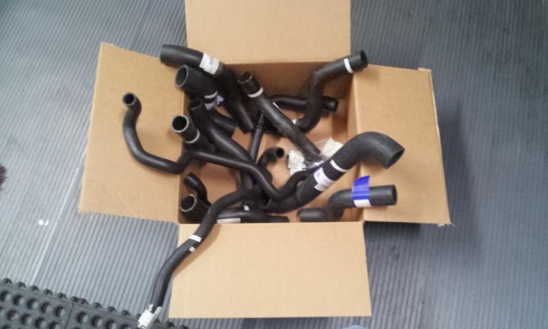
These are the two large hoses located above the transmission. There's also a small breather hose I need to order.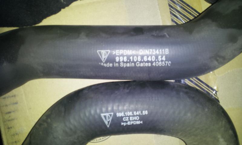
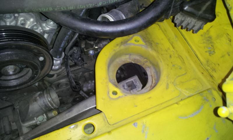
Removed the stock thermostat & housing. While there, I was able to snap a shot of the engine serial nbr. The "AT" signifies "remanufactured".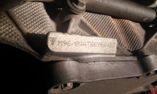
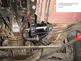
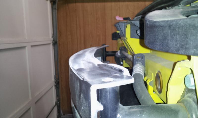
Front Mounted Coolant Reservoir for 996? Ran into a problem tonight. VF's instructions for the 3.4L 1st generation 996, shows the reservoir tank and Bosch pump as one assembly. The kit I received, instead, contains a reservoir that should mount behind the front crash beam. The only reference I can find to this reservoir is cited in the install instructions for the 997S. Has anyone installed this front-mounted reservoir tank in a 996? Damn thing just doesn't fit correctly. Here are some pics. Will call VF Engineering tomorrow.
Reservoir NOT sitting on crash beam top lip. Too low.
Reservoir NOT sitting on crash beam top lip. Too low.
Reservoir sitting on top of the crash beam top lip. Too high. Crash beam bolt does not align with hole.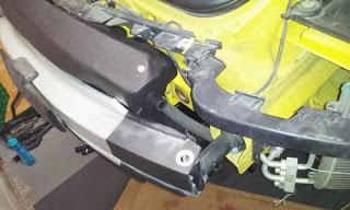
VF install instructions for 3.4L 1st gen 996. (Not included in kit.)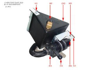
Front Crash Bean Lip Removal
Quote:
Originally Posted by IAPorscheDoc 
Doug, the early reservoir was discontinued a long time ago.
Thanks for confirming.
Quote:
Originally Posted by Purplxd
Your front crash bar looks a little different than mine as it seems like you have a larger upper lip in the middle
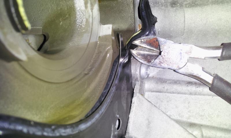
Bingo! A VF tech confirmed that on "older 996s" (perhaps he means 1st generation?) the lip has to be cut off.
So, as Aaron and VF alluded, the crash beam lip needs to be trimmed in order for the tank to fit correctly. There are two threaded nuts molded into the back side of the reservoir tank. Jeff @ VF mentioned that it is no longer necessary to attach the tank using these fastening points, as the tank will fit pretty snug. I may attach it anyway, just to prevent the possibility of future rattles.
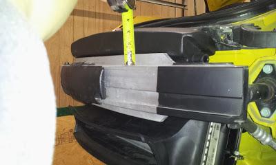
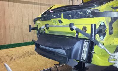
Lip measures approximately 1 inch.
3rd radiator installed with the "air flow guide". I hope the aftermarket NR Auto bumper will not interfere.
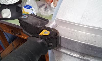
Using reciprocating saw. A perk to doing these DIYs is I get to buy new tools! Tonight going to buy an angle grinder to smooth out the cut.
The groundhog says spring is coming early! Motivation to get this project progressing faster!
Crash Beam, Motor Mounts, Water Pump, Thermostat
Here's the latest from this weekend. I hope some of the parts from Suncoast come in this week. As I mentioned in a previous post, having to cut the crash beam lip off justified my purchase of a 4 1/2" DeWalt grinder. Turned out pretty dang smooth after a last smoothing with 120 grit wheel.
I really need to install the new injectors, but I've been stalling, cause I heard it is one of the most difficult tasks.  Hmmm, come to think of it, I should have done that beforetightening the carrier to the motor mounts.
Front crash beam without the top lip. Reciprocating saw, grinding wheel, and 120 grit turned this into a beauty! The coolant reservoir fits now!
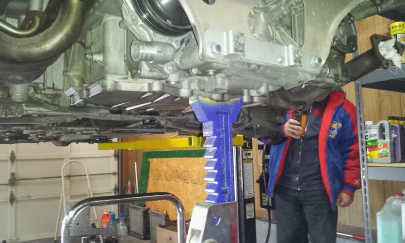
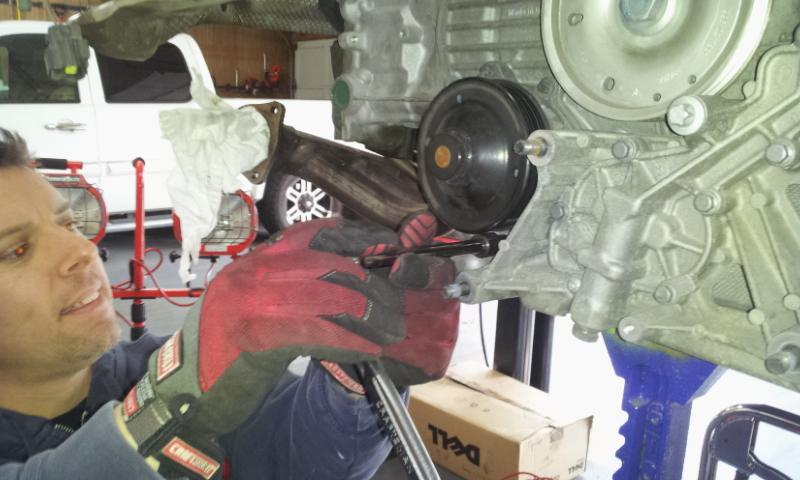
Supporting the engine for replacement water pump, thermostat, motor mounts.
My trusty assistant "dad" feathered the MaxJax pressure release lever with one hand, the other hand was for coffee drinking. (Yes, men's KU b-ball lost AGAIN! (3 in a row). Unbelievable!  )
)
Motor mounts removed. Carrier shown below the hole. After much research, I will be replacing them with.... wait for it, wait... read on.
Water pump removal. Who says Android mobile app developers can't wrench!
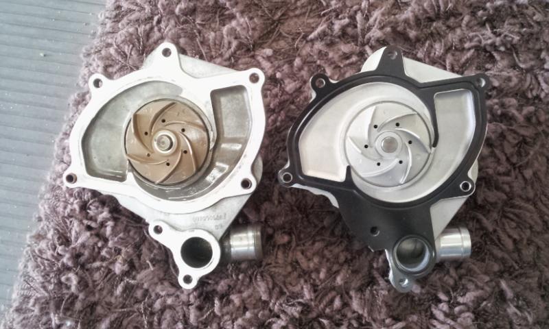
The water pump is in great shape.
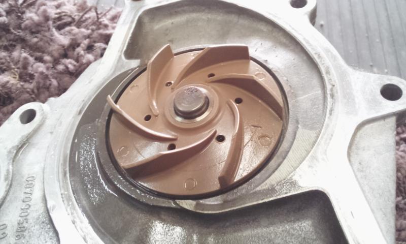
Part of the OEM gasket is used behind the component to the right of the waterpump. Have to snip it away in 3 places before installing the new one.
OEM waterpump on the left, aftermarket ($100ish) metal impeller on the right. Learning from the master technician in KC, I checked the bearing would actually spin (although it took a bit more force to do so). There's been some debate about using metal impellers. In the end, it was almost $200 cheaper. I hope it doesn't become the achilles heal. LOL).
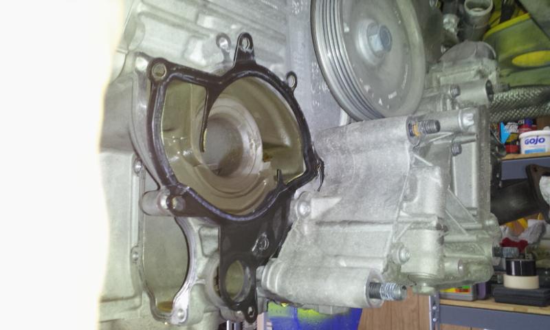
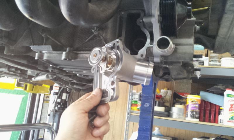
New low temp thermostat. The bolt torque for the waterpump and thermostat is 7.5 ft/lbs
If you're read this far, you're probably wanting to know what motor mounts are going in.
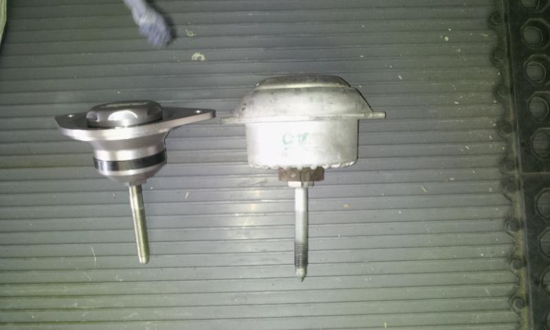
RSS Semi-Solids. From my research, it's a good compromise between hydraulic and solid (for the price). http://rss.rpmware.com/rss/rss_perfo.../i-533242.aspxTorque top bolts to 25 ft/lbs, bottom nuts to 63 ft/lbs
Fuel Injectors & MAF Resistor
I had planned on working from the front of the car to the rear. That changed though. Early last week, I struggled with connecting one of the coolant hoses (from the SC coolant reservoir to the top inlet of the center radiator), and came to find out, it was the wrong length! So... what to do... oh yeah, the dreaded fuel injector swap.
Lessons learned:
- Drop the engine down a bit to gain more access. Your hands and knuckles will appreciate it. Swap the injectors when replacing the motor mounts, not after (duh)!
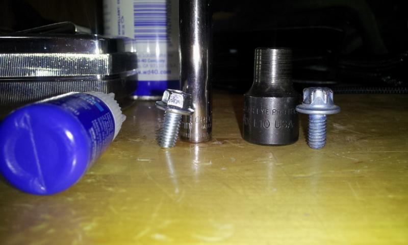
- Use a 5/16" socket to remove the two torx screws holding the fuel rail. An E10 socket's wall is too wide, and bumps against the intake. I replaced the torx with 8mm hex head screws (with thread lock goop).
- As many have suggested, lubricate the injector o rings for easier "seating" into the rail.
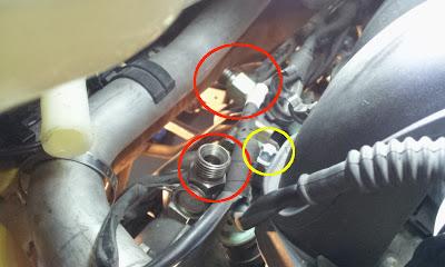
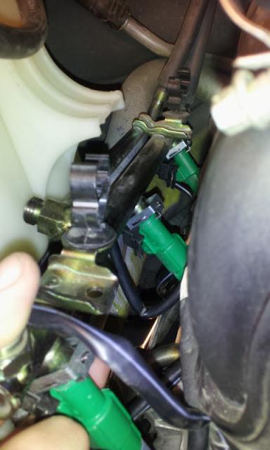
Driver Side: disconnected the fuel lines (marked with red circle). There are two E10 torx screws holding fuel rail (yellow circle). I used a 5/16" socket to remove, and replaced with 8mm hex head (see above for reason).
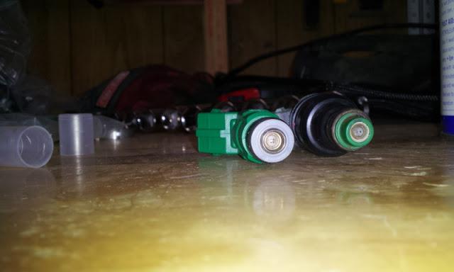
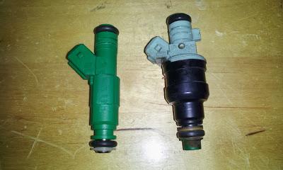
OEM injectors
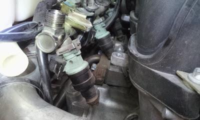
VF Eng. on left (4 spray holes), stock on right (2 spray holes).
New injector installed. Assured the snap ring was securely fastened (and that the metal tab was sticking through the ring. I had bent one earlier while removing the OEM injector).
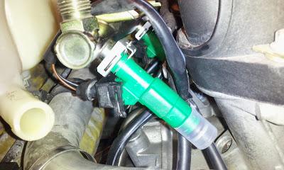
Was easier to disconnect the injector closest to the front of the car by accessing it from underneath.
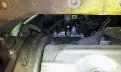
All three injectors installed into the fuel rail.
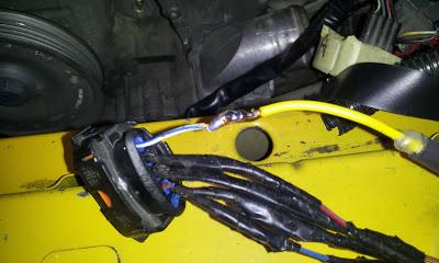
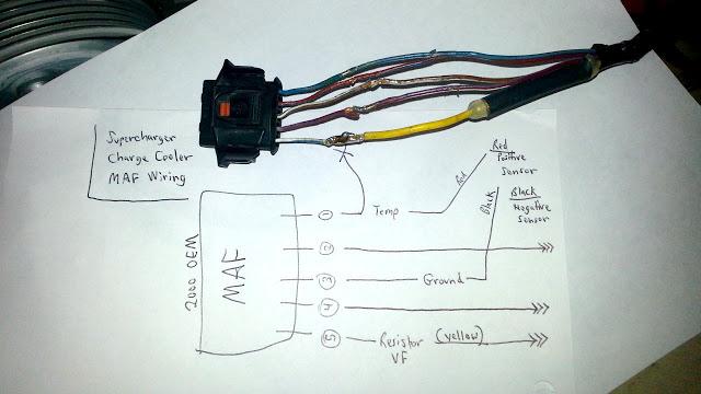
Here's the inline MAF resistor. As evident by the electrical tape, this MAF connector had been spliced into before (probably EVOMS when installing the 1st prototypes of the SC).
Solder the white wire/blue stripe.
SC Coolant Line Routing
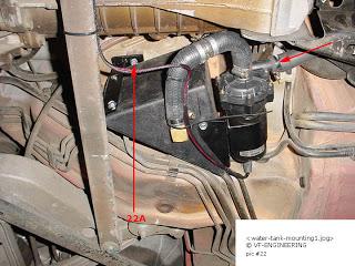
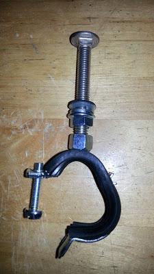
I managed to accomplish some other tasks as well. Remember a few posts back, where I mentioned suspending the SC coolant line hoses that run parallel to the aluminum supply & return engine coolant pipes? Here's what I came up with -- rubber clamps with a welded top nut (from zorotools.com). This is overkill, I know... but pretty cool idea, if I must say so myself. The photos and commentary below speak for themselves.
Question: Is the hose from the driver side coolant tank to the Bosch water pump supposed to travel *above* the transmission brace? I have it that way now, but when I move the tranny back up, the hose gets pinched. I could run it underneath, but then I would have to disconnect the hose anytime in the future the tranny would need to be dropped for service. I forgot to capture a photo
----------------
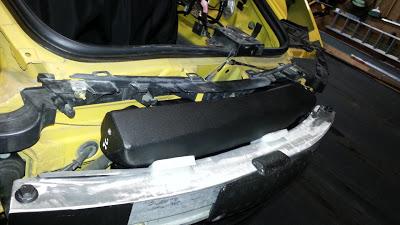
I didn't like the idea of the coolant reservoir just being wedged between the front bumper bar and the body of the trunk. Using the two nuts, molded into the reservoir, it is now securely fastened to the body of the car with bolts. The hood latch mechanism is easily removed to gain access. (These mini-tasks is what is eating up all my install time! LOL)
Coolant reservoir securely fastened.
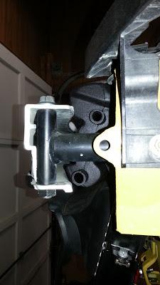
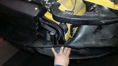
If you want to use the OEM radiator shroud, do NOT position the hose this way.
Instead, position the hose like this. Zip ties help keep in in place.
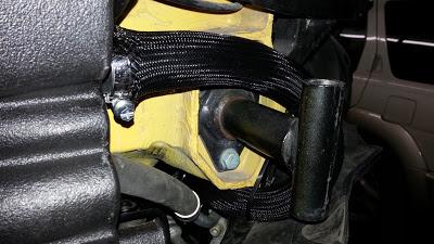
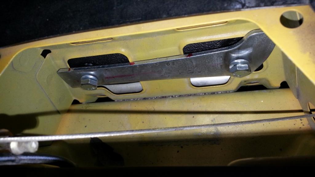
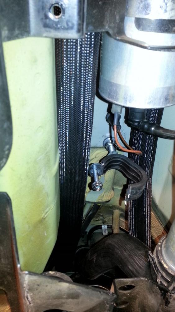
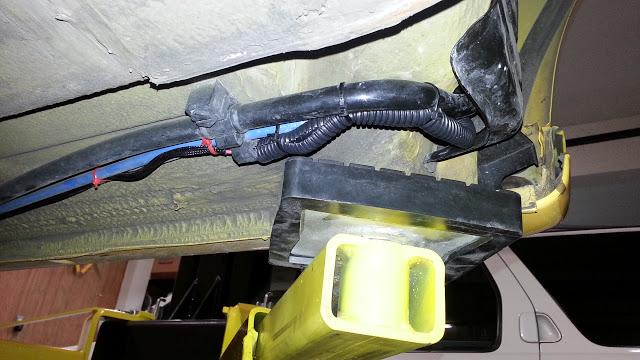
This is the assembly for suspending the two SC coolant lines in the transmission tunnel. The nut is already welded onto the clamp.
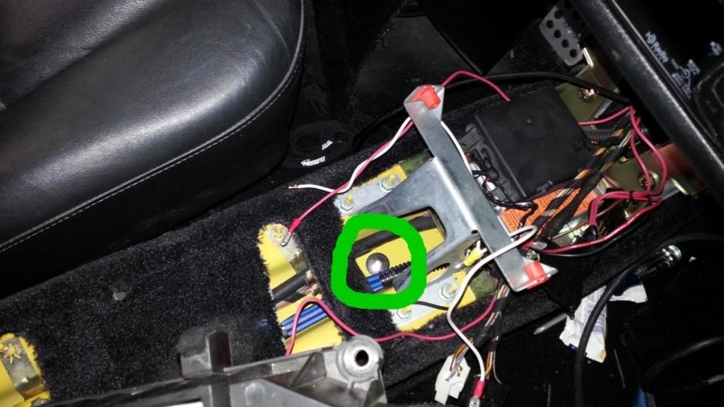
Remove the center console and drill a hole here (in green).
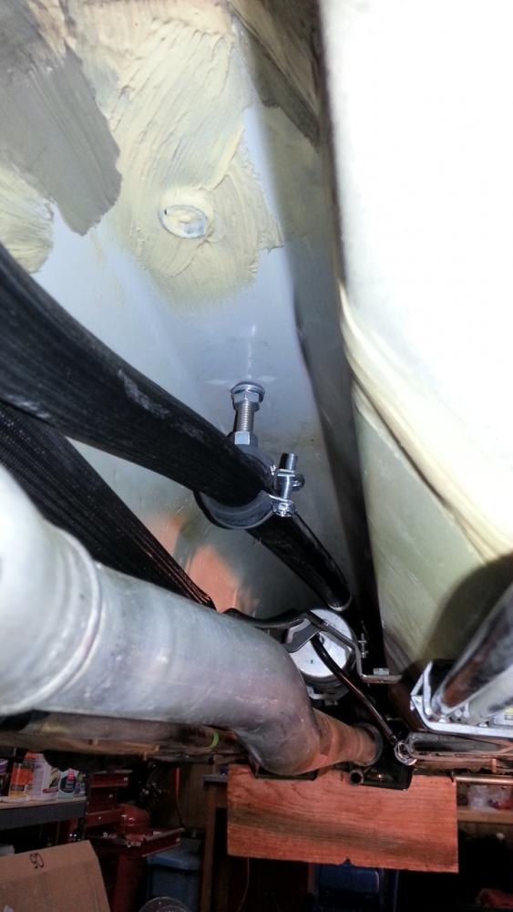
And fasten the assembly. So far, only the top aluminum coolant pipe is installed.
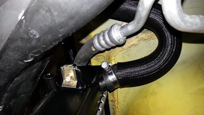
Drill another hole underneath the parking brake cables. Insert bolt.
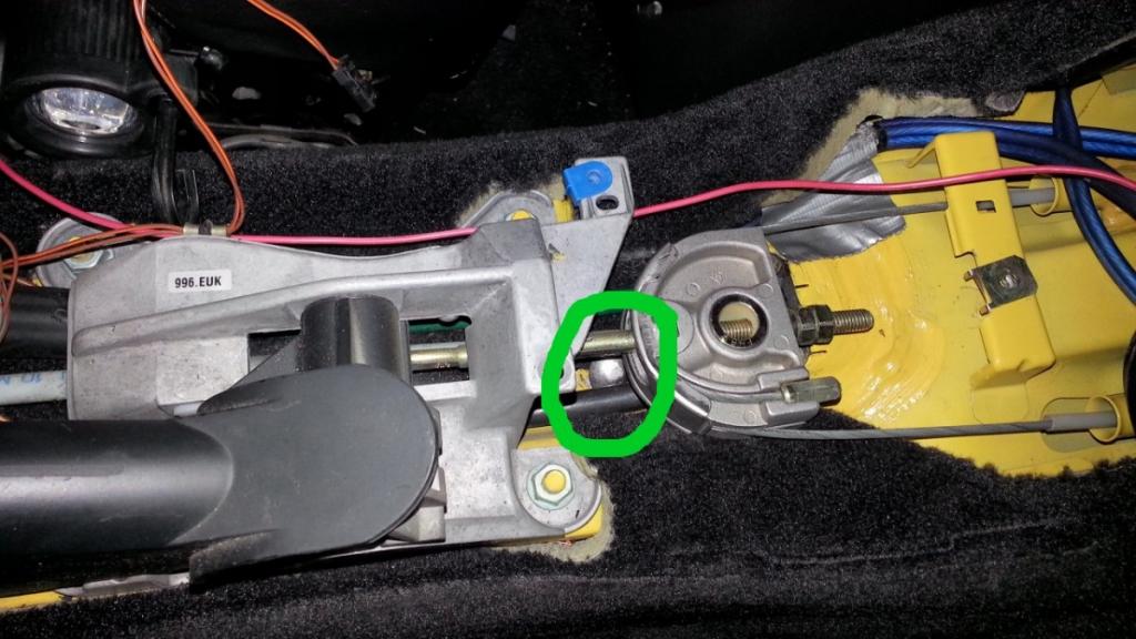
The hole should be approximately 2" from the fuel filter electrical line (as shown by the black gromet).
Lastly, the water pump was mounted to the aluminum crossbar. I still need to hook up hose, but first want to find out if the hose should be run above the transmission, or below (see blue text question above).
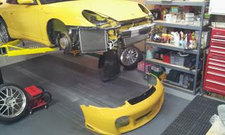
It's been a while since I posted. The supercharger is in, and the car is running great! No CELs after 300 miles. The car pulls really hard, starting at around 4500 RPMs. Here are some photos from the last several months. Next on the project list is installing an AFR gauge, boost gauge, and IAT gauge. Also, I've contacted the shop that did my initial dyno (post #1) about doing another dyno session. Enjoy!
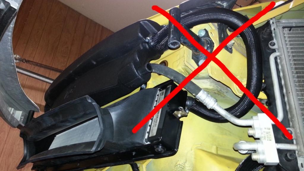
VF's version 3 has a thermostat threaded into the cold side of the chargecooler. This thermostat, when wired to the MAF, provides a more accurate IAT to the DME.
This is the bracket that holds the overflow/refill tank.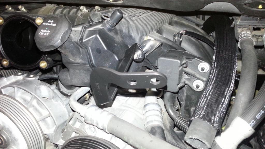
The DME is located back here on cabriolets. Put the top in the "service position" and prop it up with a jack handle 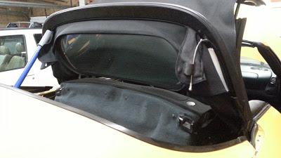
The DME. Remove and send to VF for flashing.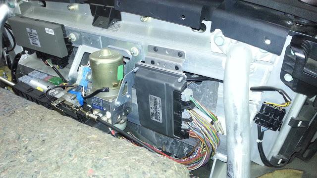
DME removed.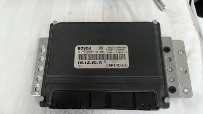
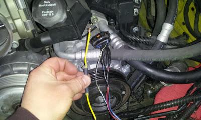
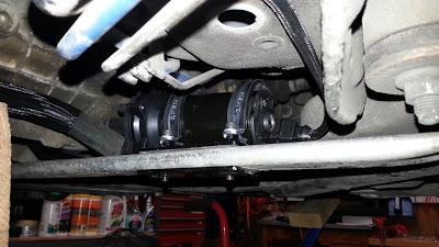
This is the 12V relay (blue) for powering the Bosch water pump.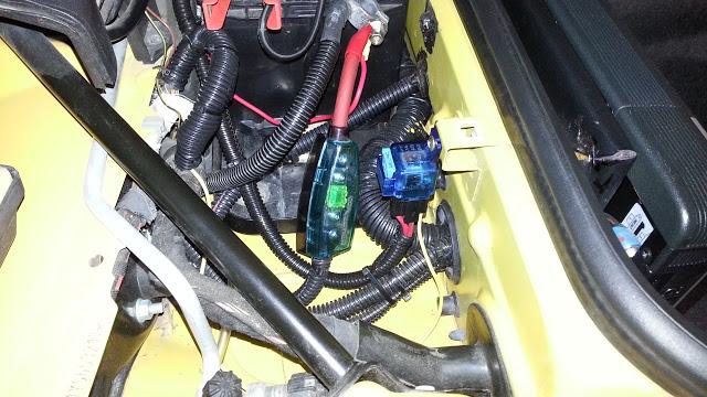
Beside the batter, find the black and yellow wire that will power the relay when the ignition switch is turned on.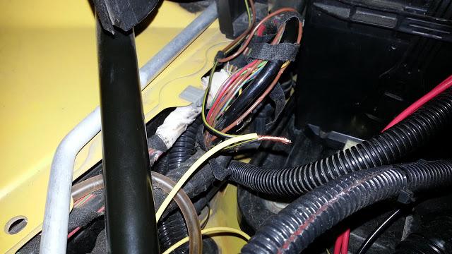
Run the red wire from the relay to the water pump.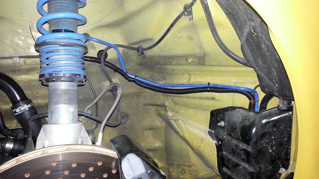
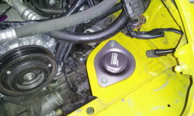
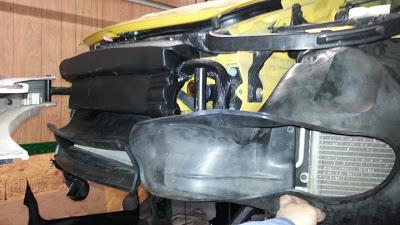
997 pulleys fastened to the supercharger.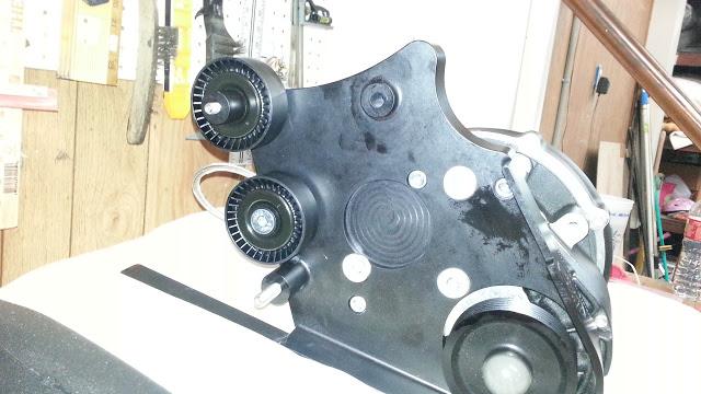
Extra long bolt and spacer.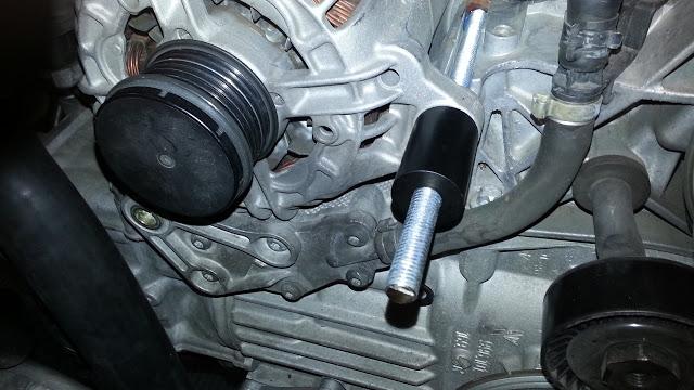
Mounted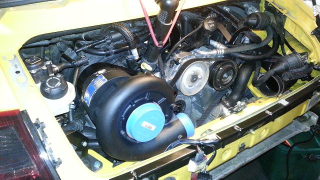
Supercharger compressed hot air (via silicon tube) photo 1.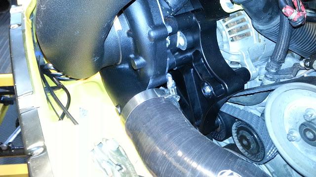
Photo #2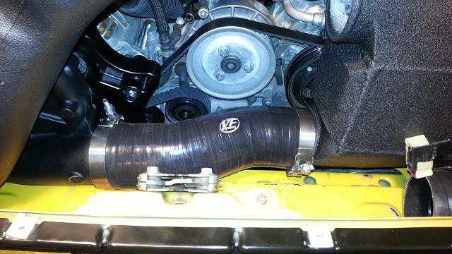
The overflow/fill tank. On the chargecooler, you can see the IAT thermostat mentioned in a previous post.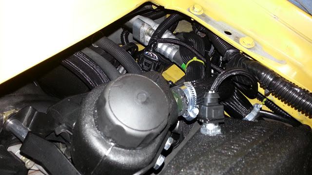
Used a UView to vacuum in the coolant. Capacity was a little over 2 gallons.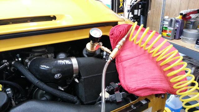
Final Photos
Final Photo #1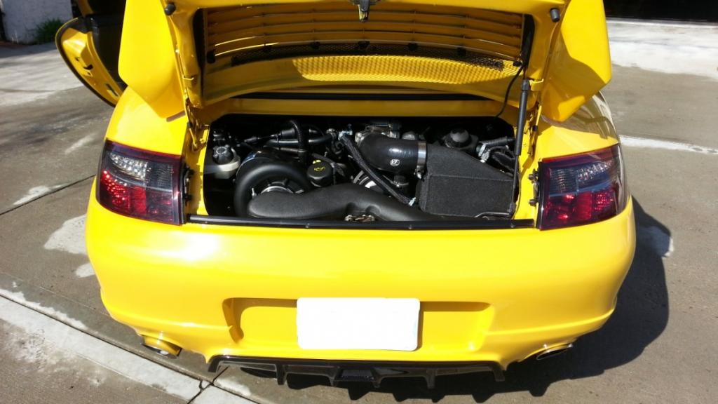
Final Photo #2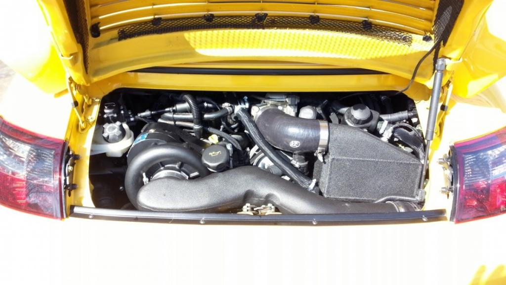
Washed up, and ready to run!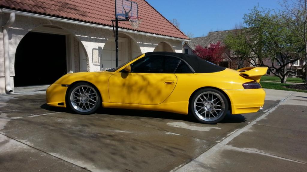
Next on the list:
1. Drive the car and enjoy the new power!
2. Dyno session.
3. install catch can (http://store.42draftdesigns.com/Stea...Can_p_289.html or http://jlttruecoldair.com/ZenCart/in...ndex&cPath=378 or recommendations.
4. Custom Exhaust (TIG Welded T304, no cats, exhaust will exit same side as head -- no crossover)
5. Install AFR gauge, boost gauge, IAT gauge
Yes, very noticeable. Today I mashed the pedal in 2nd gear at around 3700 RPM and took it up to 6500 RPM before shifting to 3rd. It feels like a different car! I'm looking forward to more break-in miles before the true measurement is taken with a dynamometer.