You must be logged in to rate content!
40 minute read
B5 Control Arms and Tie Rod End Assemblies
Compliments of jdahlen24 @ www.audiforums.com
Part 1: Preparation
Alright, alright. It's time to save some money and have some fun by changing these components ourselves.
This job was by far the most challenging one I've attempted on my B5, yet it went the smoothest of all the jobs I've done. While researching and preparing to do this job, all of the DIY's I found seemed to be tailored to the seasoned amateur mechanic, so I decided to do a DIY for those of us who have far less experience. All of the suggestions and advice I give here were given to me by others on this forum who are far more experienced than I am. In fact, I don't think I had an original thought in this whole series. All I did was take pictures and organize the great advice I got from others into this DIY.
I'm using so many pictures that I have to split this into multiple threads. I have therefore decided to split this into four parts:
1) Preparation
2) Replacing the Inner and Outer Tie Rod Assemblies
3) Replacing the Upper Control Arms
4) Replacing the Lower Control Arms
Alright, so let's begin. First of all, let's talk about the tools that will be needed for this job. Here's what I used:
Hex(Allen) sockets: 7mm, 10mm, 17mm(This one must be a 1/2" socket)
Box end wrenches: 13mm, 16mm, 17mm, 18mm, 22mm, 24mm(if using the front end service kit)
Ratchets: 1/4", 3/8" and 1/2"
Sockets: 10mm, 13mm, 16mm, 17mm, 18mm.
- 3/8" Torque wrench
- At least one adjustable wrench.
- 25" x 1/2" breaker bar
- 30" x 1" galvanized pipe, to use as an extension for the breaker bar.
- Short flathead screwdriver
- Set of various size punches
- Pry bar
- Carpenter's hammer
- 4lb sledgehammer
- Can of PB Blaster
- Large zip ties
- OTC Front End Service Kit
- Advance Auto Parts special rental kit #85 - Inner tie rod enter removal kit.
- Mapp gas torch
- Tire iron to remove the 17mm lugnuts from the wheels
- A good pair of impact resistant and chemical splash-proof goggles.
- LED headlamp for your head(invaluable when working on the inner tie rod ends. Nothin' like hands-free light!)
Here is a pic of most of the kit I used:
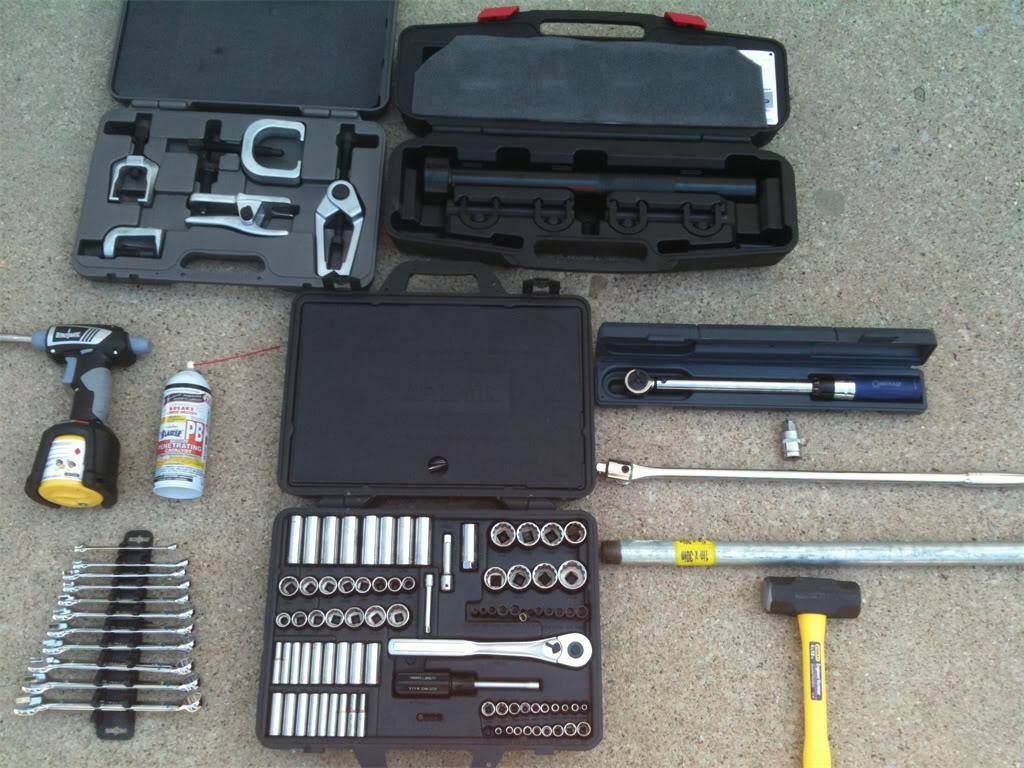
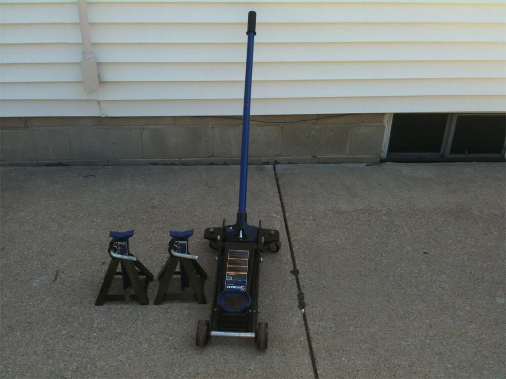
We'll also need a good jack and a couple of jack stands for safety!
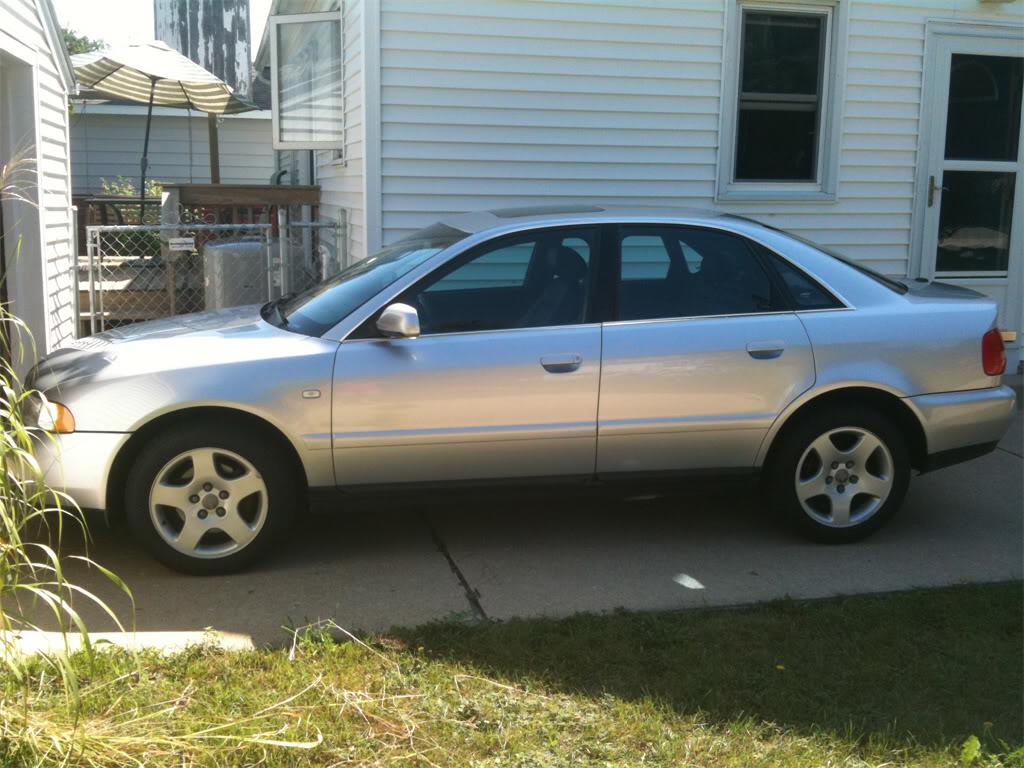
Here is my beloved 1999.5 Audi A4(Sexy wheel gap FTW!)
A few days before you begin this project, I strongly recommend spraying the nuts and bolts of the upper control arms, lower control arms and tie rod ends with PB Blaster so that you have a better chance of breaking them loose without snapping a bolt head off. I am speaking from experience, people. Trust me, you don't want to snap off a pinch bolt head if you can help it!
Right, get yourself organized and let's do this!
There are two ways to do this job, one way is to remove the wheel bearing housing(also called the "spindle"). The other way, as you may have cleverly guessed, is to leave it mounted. Since I was planning to do a DIY writeup, I decided to do it both ways to see which way was easier. In the end, I didn't think either way was better than the other. If I had to do it over again, I probably would have left the spindle attached. Removing the spindle freed up room to work on the inner tie rod end assemblies, but having to deal with the removal of the spindle and the remounting of it, was kind of a PITA. If forced to give an opinion, I would say to leave the spindle alone unless you need to change the wheel bearings.
If you decide that you want to remove the spindle, start with step one. If leaving the spindle intact, you may start with step two.
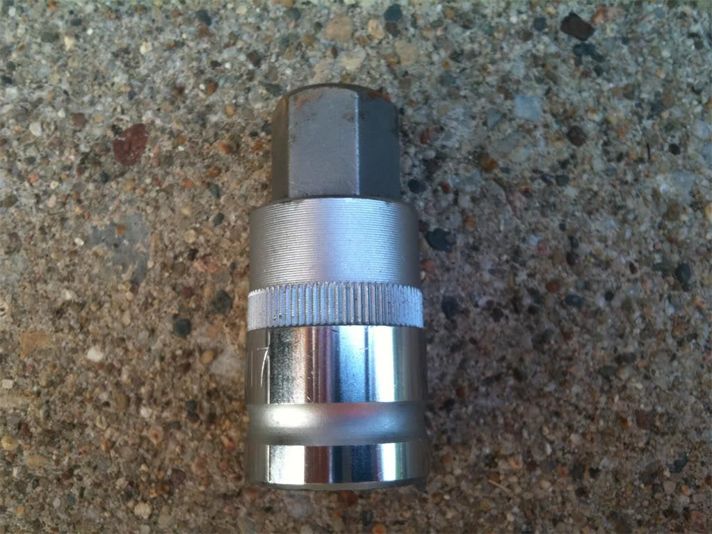
Step 1. To remove the wheel bearing housing(spindle), we first need to loosen the axle bolt while the car is still on the ground. This requires the use of the 17mm x 1/2" hex socket, the 1/2" breaker bar and the galvanized pipe. Remove the lugnut caps and center cap.
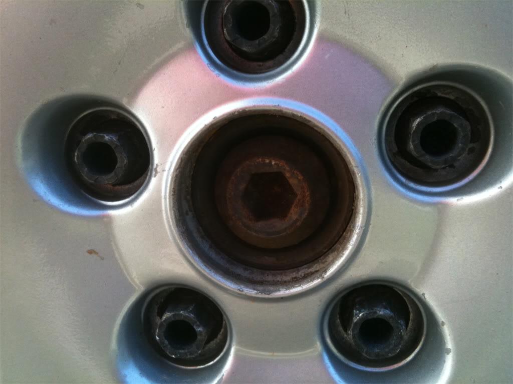
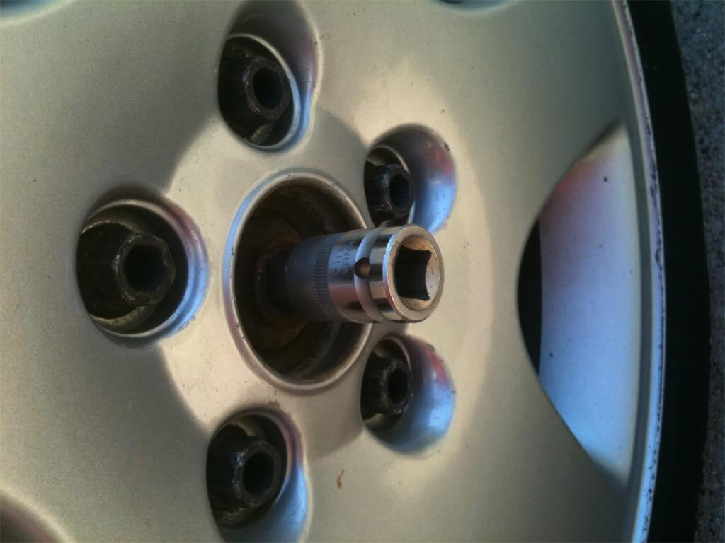
Here's what the 17mm hex socket looks like. It's a big one!
Step 2. Make sure that you insert the hex socket all the way into the axle bolt, otherwise it may slip while you're applying pressure to break it free. I used a hammer to lightly tap on the socket until it was fully-seated.
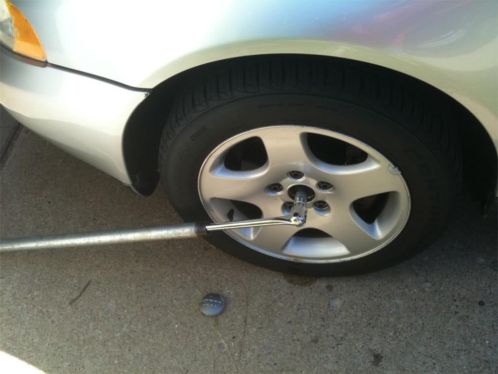
Step 3. Attach the socket to your breaker bar, then slip the 1" diameter galvanized pipe over the breaker bar. Remember, lefty-lucy. When you're ready, do your best Hulk Hogan impersonation and break that bolt loose! I said pull! It'll SNAP! when it breaks free. Whew, that took a bit of pressure. My back hurts already! This picture was taken after the snap. The original position of the bar & pipe was about 11:00.
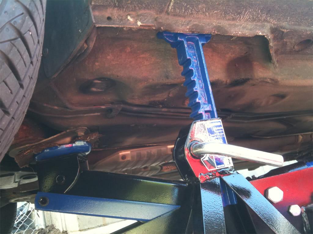
Step 4. Now it's time to jack up the car and put it up on jack stands. Place the jack under the car and use your favorite spot to jack it up. I always use the sub frame shield as shown here.
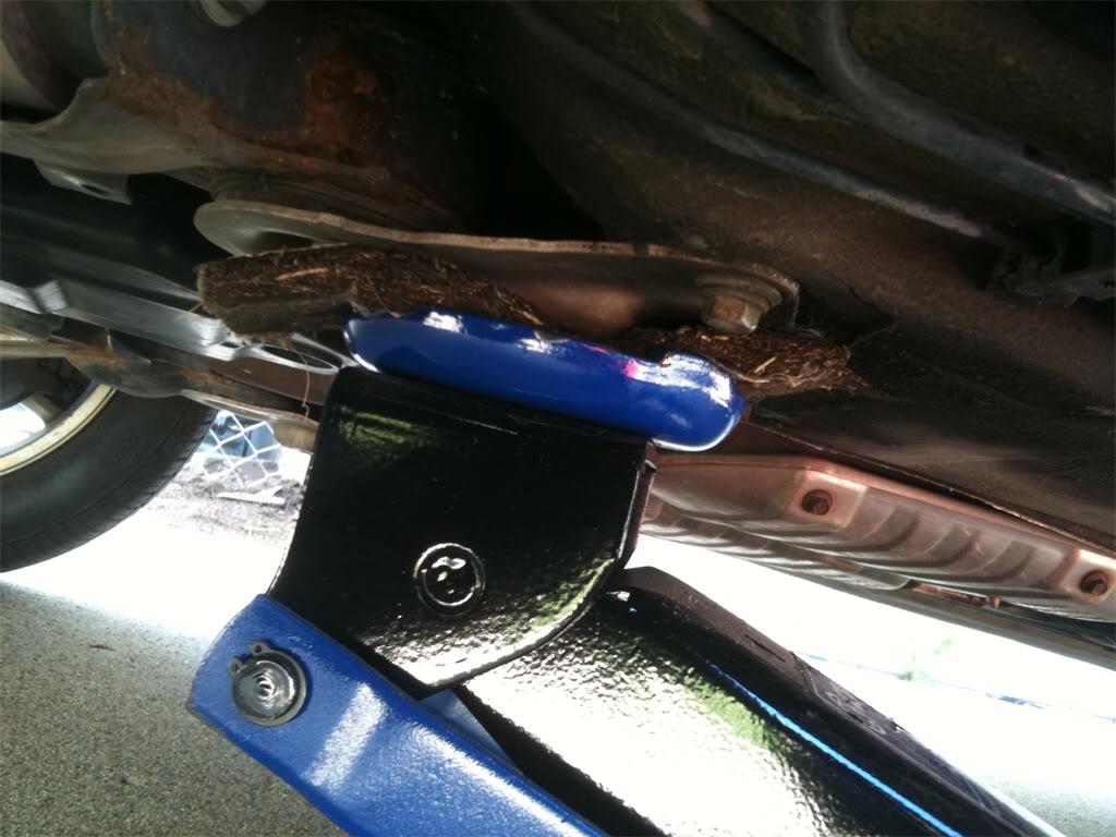
Step 5. Slide the jacks up under the car and then lower the car back down, making sure that both jack stands are on the same "notch" and are evenly handling the weight of the car. Here's a close up showing where I positioned the jack and the jack stand
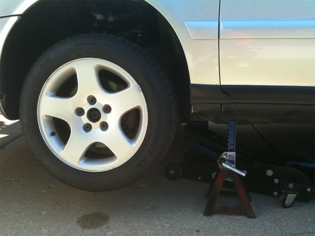
This is how the car looks when sitting on both jack stands.
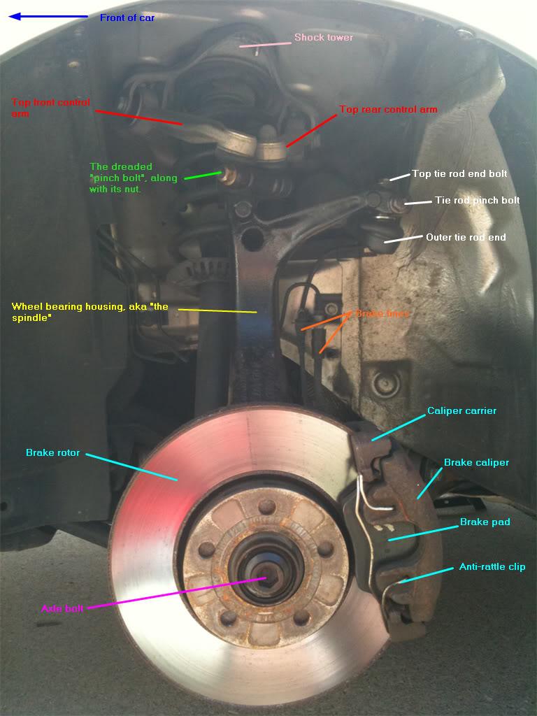
Step 6. Remove the 17mm lug nuts from each wheel, and then remove the wheel and set it aside. You will now be able to see the major parts of the front suspension and brake system. Notice how a nice shot of PB Blaster removed the rust look from the axle bolt. I was also surprised that my suspension was not more rusty than it was, considering that I live in the frozen tundra of Minnesota. This car has seen many winters worth of snow, ice and road salt.
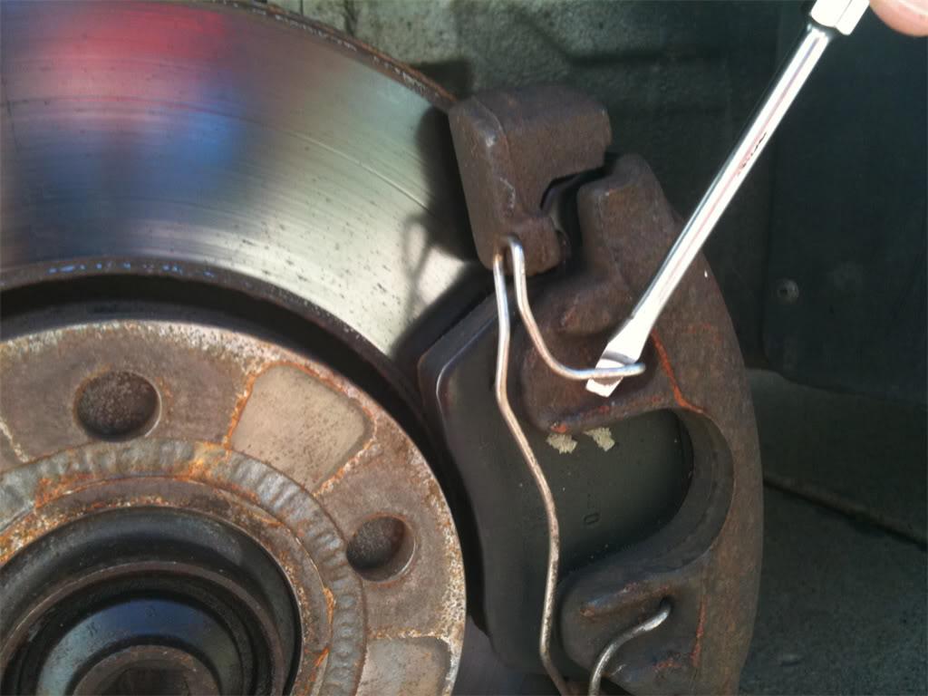
Step 7. Alright, lets get those brake parts off so that we have access to the lower control arms. First, we remove the anti-rattle clip from the caliper. A flat head screwdriver works well for this. Just pry it off carefully and set it aside.
Step 8. Next, we locate the two caliper bolts that reside in back of the rotor, hidden inside of rubber housings. Pop the caps off these housings with your flat head screwdriver.
Then insert the 7mm hex socket that's attached to your 3/8" ratchet. The pic below shows what it looks like with the socket already inside the bolt. Finally, remove both bolts.
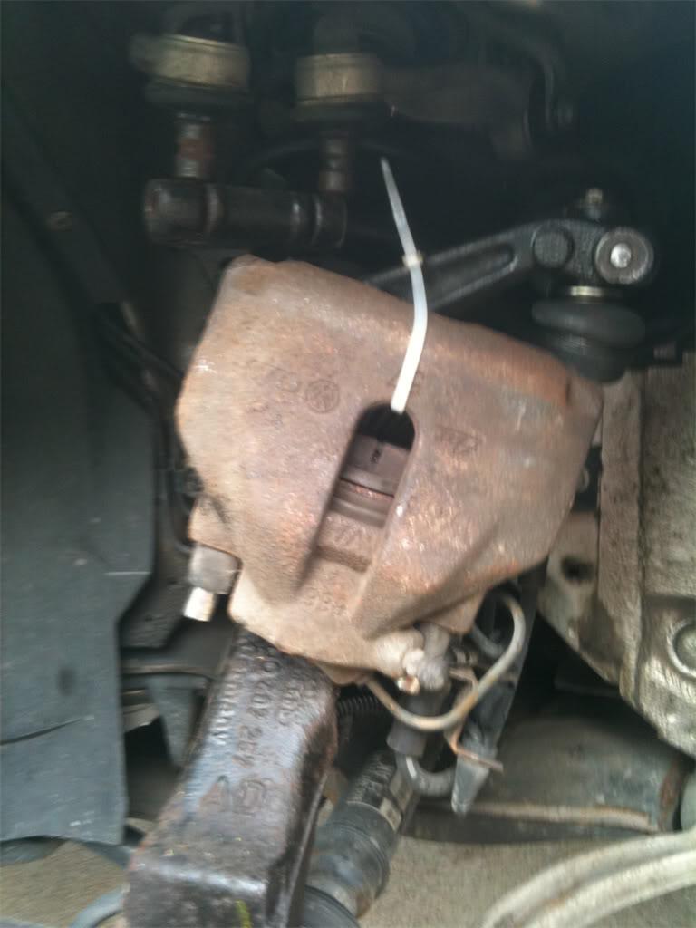
Step 9. With the bolts removed, you can carefully pull the caliper assembly off of the rotor & spindle. I had to insert a large flat head screwdriver into the slot on the caliper to help pry it off. When it's removed, either set it down on the lower control arm like this...
or hang it from the spindle using a large zip tie as shown here. Either way, the goal is to not stretch the rubber brake lines. DO NOT LET THE CALIPER HANG FROM THE BRAKE LINES!
Step 10. Now that the caliper is removed, you'll want to remove the carrier. On the back side, find two very rusty 18mm bolts that you will spray with PB Blaster, and maybe even heat them up with the mapp gas torch before the attempt to break them free.
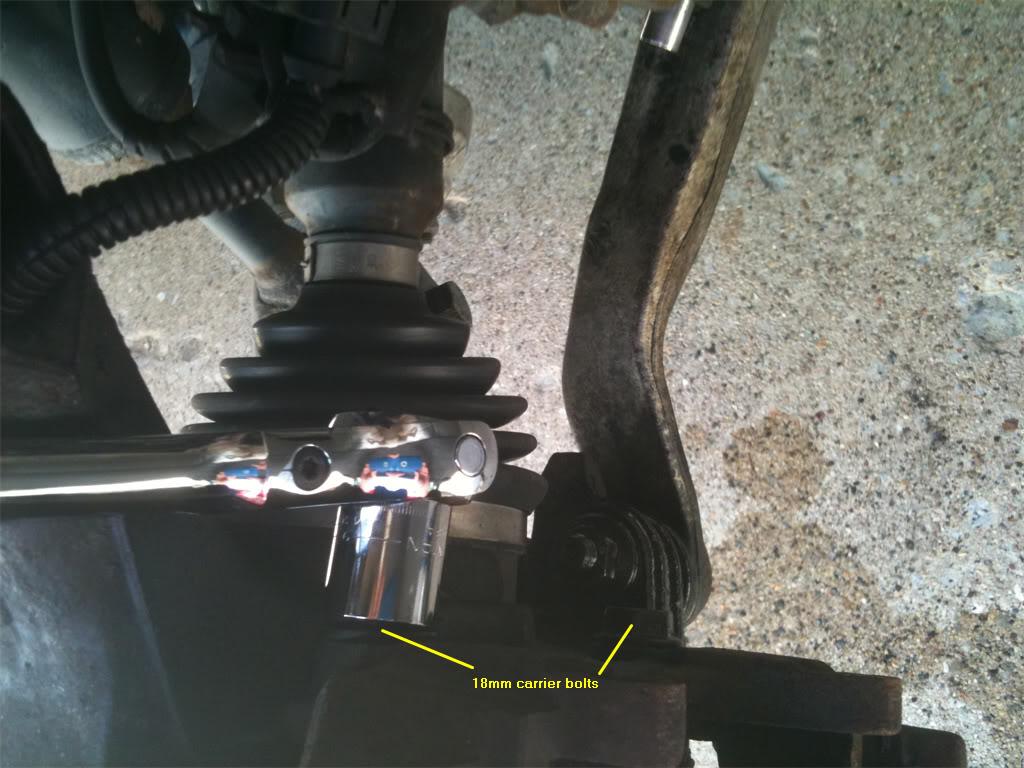
The idea here is to break free the bolts without breaking the bolts or the heads off the bolts. That's why it's always a good idea to let them soak in PB Blaster for a bit, or better yet, apply some mapp gas heat to them. Nothing breaks through rust like mapp gas heat. Alright then, remove the bolts, then set the carrier aside. Now you may remove the brake rotor from the spindle.
With the brake rotor removed, here's what you're left with.
Great, you've got the brakes out of the way. Now you get to do what you came here for. Let's change out those old rotten tie rod end assemblies and control arms!
Part 2: TRE Replacement
In part 1, we prepared your car for the replacement by jacking it up and removing the brake components. In part 2, we get to the real meat of this DIY.
Ready to begin? Good, let's do it!
Step 11. It's time to replace those old tie rod end assemblies, both the inner and outer tie rod ends. In order to do this as effortlessly as possible, you should run out to the nearest Advance Auto Parts store and rent this Inner Tie Rod End removal tool, kit #85. Rental of this kit is free. The way it works is that they charge your credit card aprox $100. When you return the tool kit, they credit your card $100. 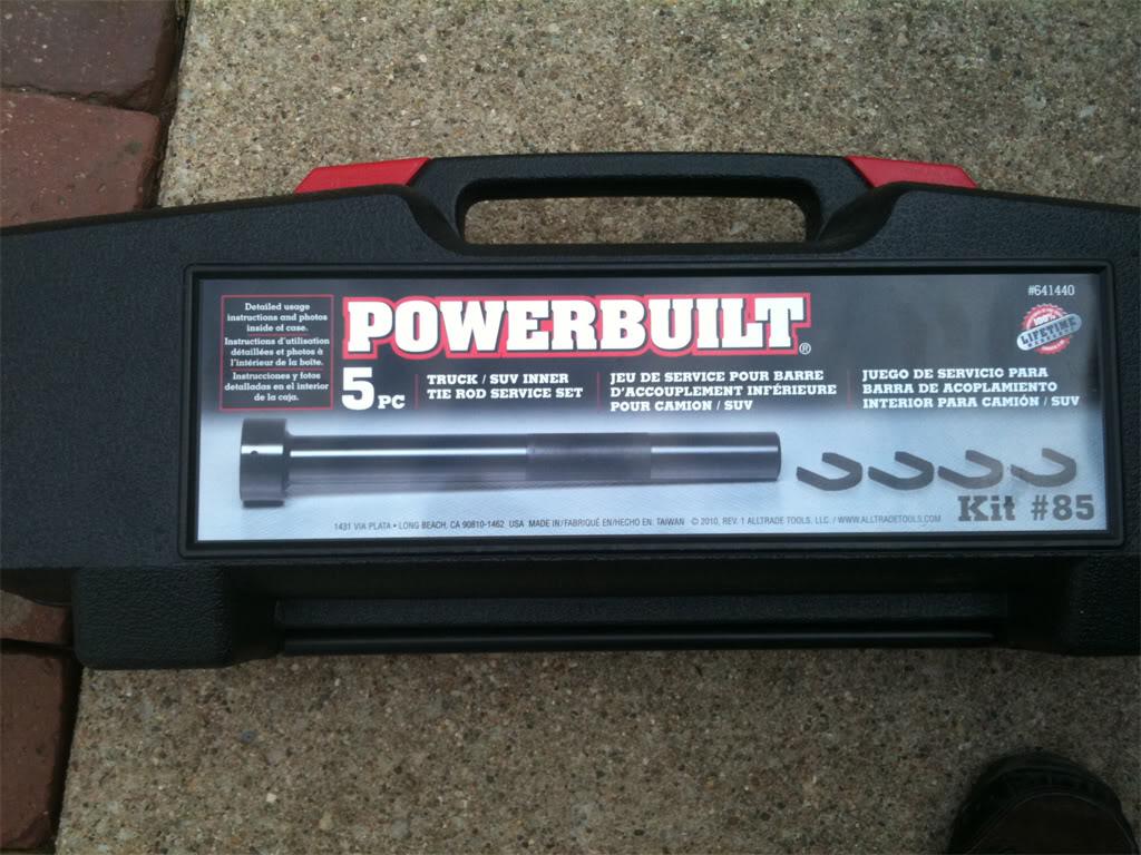
It's also possible to get away with using a short adjustable wrench to remove the inner tie rod assembly, but for me it was well worth the drive to Advance Auto Parts to rent this tool. This kit makes the removal and installation of the new inner tie rod end quick and easy.
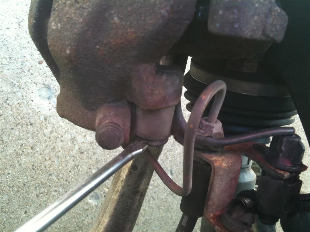
Step 12. Loosen the outer tie rod end adjustment nut using either a 22mm box end wrench or an adjustable wrench. 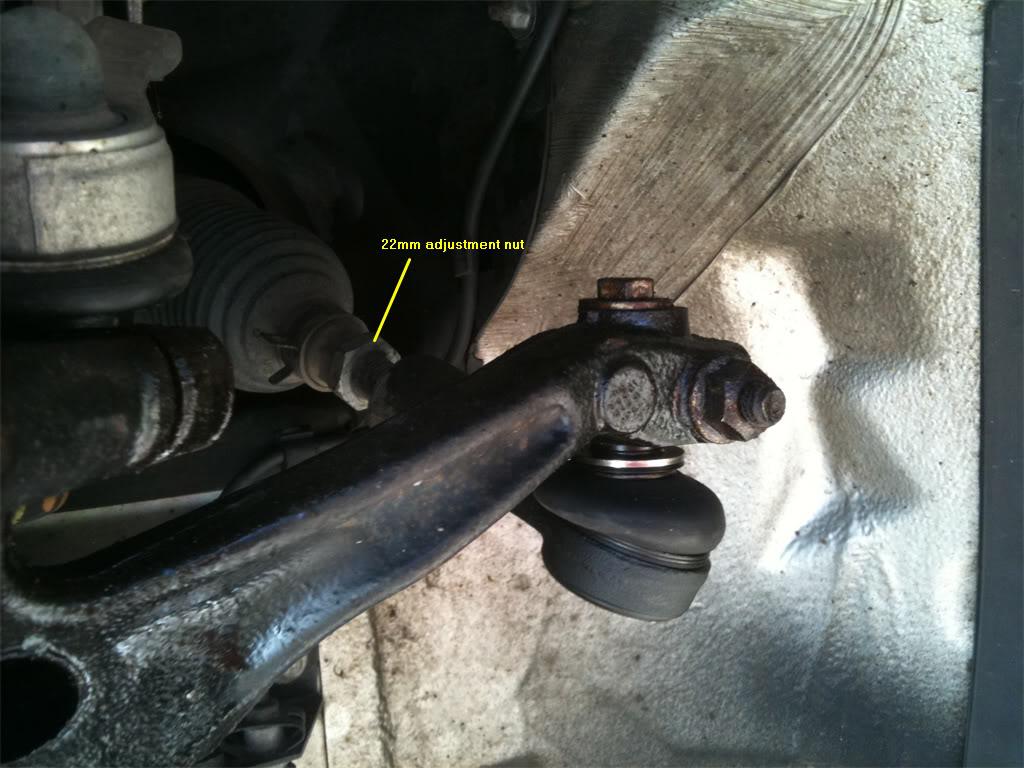
Step 13. Remove the top 13mm bolt from the spindle. This bolt came out very easily for me. Next, remove the 16mm nut that is attached to the pinch bolt. You have been spraying it with PB Blaster for the past few days, right? 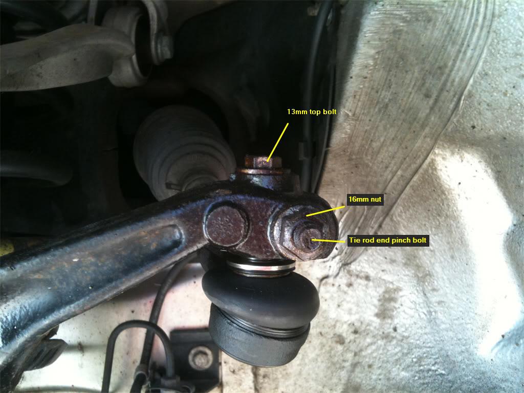
Sonofabeyotch! Look what happened when I tried to remove this nut! Snapped it right off. 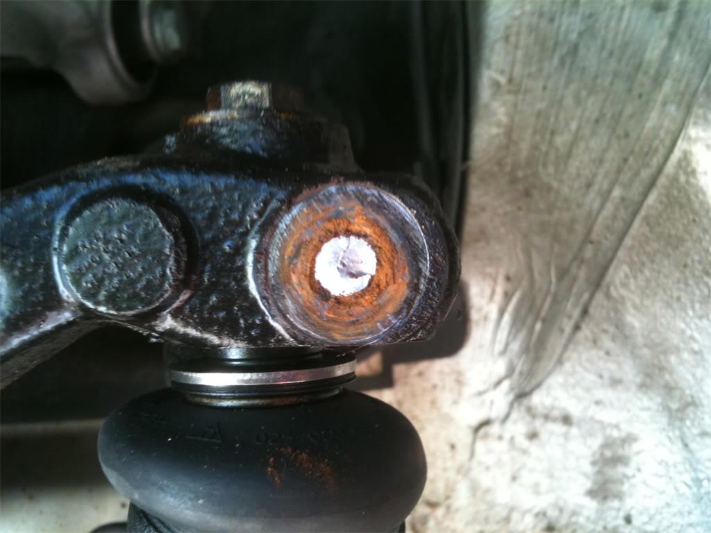
Holy cow, that thing was rusty, even with spraying PB Blaster on it for days on end before the job. Not to worry, you can overcome this! The solution to this problem was provided by one of the regular gurus on Audiforums.com, Jeremy(aka ImTheDevil).
Grab this: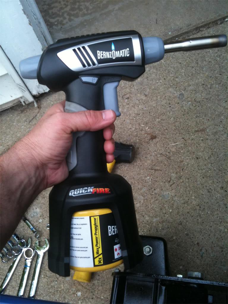
Mapp gas to the rescue! Mapp gas burns hotter than propane, so this is just what the doctor ordered. Being very careful to not burn up the tie rod end bushing, heat up the outside of the spindle where the pinch bolt lives. About a minute of heating up should do it.
Next, grab your punch of choice and that nice little 4lb sledgehammer that has been waiting to see some action. Place the punch over the pinch bolt, and start hammering for all you're worth until the pinch bolt starts to move. Since the pinch bolt is not threaded inside the spindle, you don't have to worry about any threads. Oh yeah, don't forget to wear goggles for this part. Eye patches look good on pirates, but not on Audi drivers. Safety first!
If you were able to get your pinch bolt nut removed without snapping the bolt, then you are better than poor old me. In that case, you can simply pound away on the bolt with the sledge hammer until the pinch bolt is level with the spindle. You'll have to then finish it by using the punch.
When you get the pinch bolt removed, here's what the spindle looks like: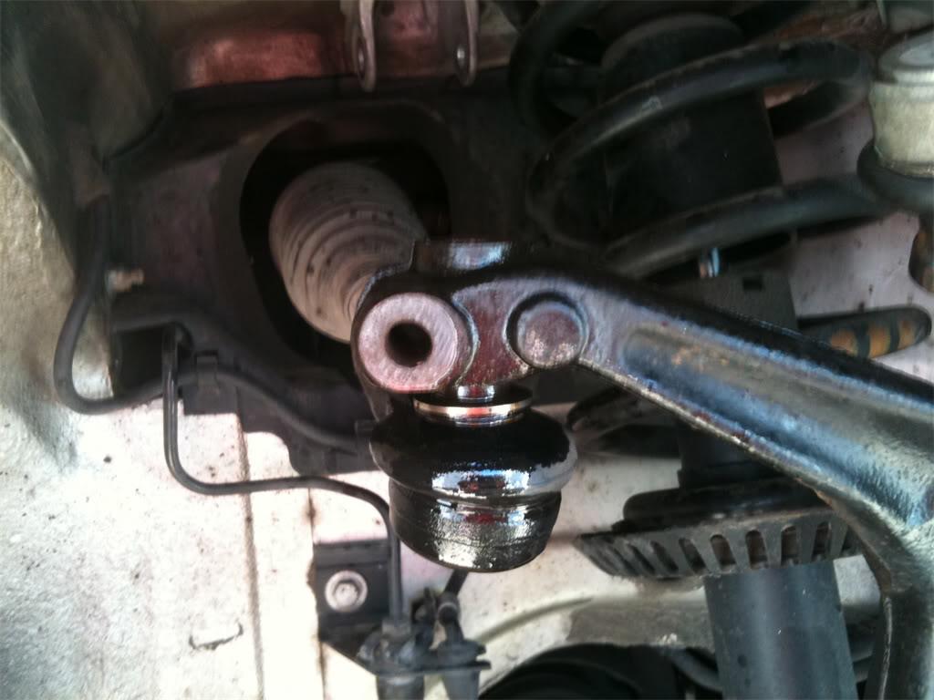
You may have noticed that that is a pic of the passenger side spindle and tie rod end, while the previous pics were of the driver's side. Sorry, but when I broke the pinch bolt, I gave up on the driver's side and moved over to the passenger side until I could find a solution to my predicament. So please excuse the inconsistency of sides. I did the best I could. The rest of the pictures of the tie rod assembly replacement will be from the passenger side.
Step 14. Now that we have the top bolt and pinch bolts removed from the spindle, we can now remove the outer tie rod end bushing from the spindle. To do this, I used this handy tool from the OTC Front End Kit that I purchased online. I was going to rent a kit, but Advance Auto Parts were out of this kit at the time, and nobody else in town had one. From my experience on this job, the $90 I spent on this kit was well worth the money for how easy it made popping the tie rod ends and ball joints out of the spindle. 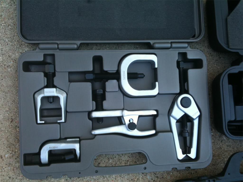
And here's what the tool looks like when ready to pop the outer tie rod end bushing out of the spindle. The bolt on the end of the tool is 24mm, so this is where the 24mm box end wrench comes in handy. Using this tool, pop the bushing out of the spindle.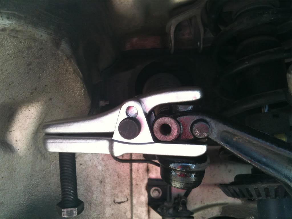
For those of you who don't have access to a kit like this, I've also discovered that by using a short, flat head screwdriver and carpenter's hammer, you can gently tap the bushing out of the hole in the spindle by placing the tip of the screwdriver into the hole and rest it on the outer lip of the bushing tip. Keep tapping with the hammer until it pops out of the hole.
Step 15. Now that the bushing is out of the spindle, you can remove the outer tie rod end from the inner tie rod end. You need to do this so that the fancy inner tie rod end tool will fit over the inner tie rod end. If you're not using the inner tie rod end removal tool, you may skip this step and go straight to Step 17. Alright, if you're lucky, the outer tie rod end will simply unscrew from the inner tie rod end without any difficulty. The inner tie rod end nut is 18mm, so you may be able to simply slip your 18mm box end wrench on that and unscrew the outer tie rod end.
If yours was stuck on there like mine was, you'll need to apply force to this situation. Grab your adjustable wrench and place it on the outer tie rod end as shown in the pic below. In conjunction with the 18mm box end wrench placed on the inner tie rod end nut, break that sucker free!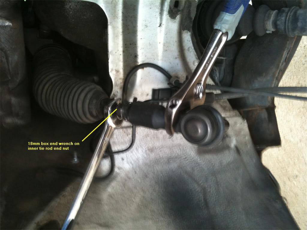
If it still won't come free, it's time to break out the mapp gas torch and heat that connection up. Be careful to not burn the inner tie rod end boot! You'll need to reuse it later.
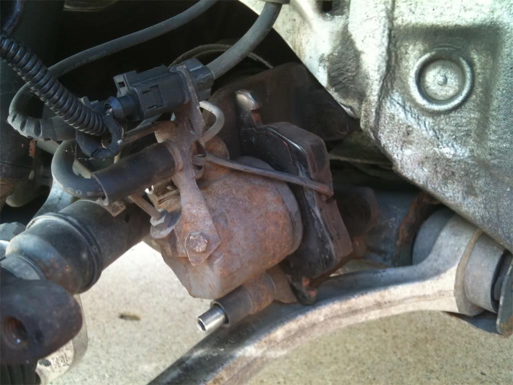
Step 16. Alright, since we've been successful at taking off the outer tie rod end, we see this: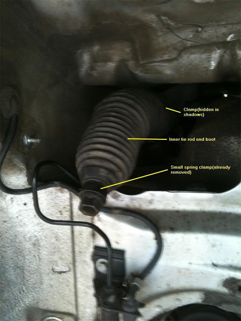
At this time, remove the black plastic covering that is in your way to getting better access to the large hose clamp on the inside of the inner tie end boot. There is a 10mm nut to remove(in the pic above you can see the bolt where this lived), as well as two plastic rivets that pop off by using a flat head screwdriver. I apologize for not having a pic of these items before removal. I was getting impatient and forgot to get a pic of them before i removed the panel.
After the access panel is removed and set aside, it's time to remove the two clamps that are holding the plastic boot to the inner tie rod end. The smaller of the two is a spring clamp, and can be easily removed by compressing both ends with a pair of pliers. The larger clamp on the inside of the boot is a little trickier to get at. If you listened to me and bought yourself an LED headlamp, this is the time to put it on and shine that light up into the area so that you can see the inside clamp. Using a flat head screwdriver, insert the tip into the rectanglularish hole on the clamp and push down on it until it pops free. This is one of the most tedious parts of the job. Keep at it until you get it. You can do it!
You got it? Excellent! Now, with both clamps removed, carefully pull the boot off of the inner tie rod end. You can now see the inner tie rod end for the first time. Yeah, I didn't know that's what they looked like, either.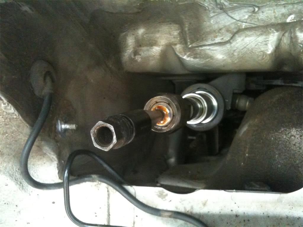
Step 17. Place the 38.4mm adapter from the kit onto the inner tie rod nut, like this: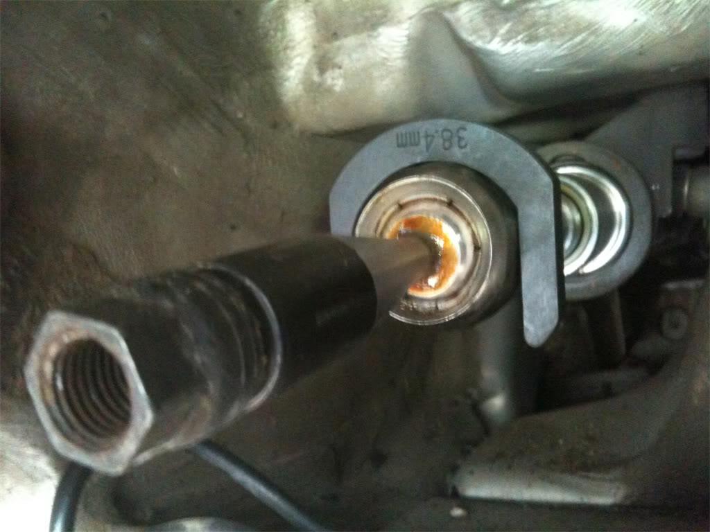
Next, slide the big long black pipe over the inner tie rod end and adapter. The end of the pipe is keyed to match the adapter, so rotate it around until you feel the adapter sink into alignment with the pipe. When that's done, attach your 1/2" ratchet to the pipe, and turn counter-clockwise to loosen the inner tie rod end. When that is accomplished, unscrew the inner tie rod end and thank it for it's service before you throw it into the trash.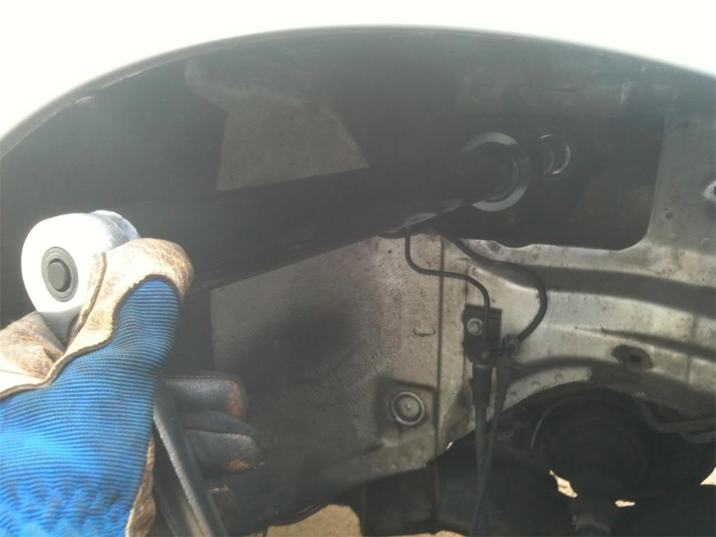
Before we install the new inner tie rod end, let's talk about the boot that was covering it. On 99% of B5's, both sides have a 7.5" boot. A very small percentage, however, have a 10" boot used on the passenger side for some reason. I discovered this when I ordered a pair of new boots from blauparts.com. I was confused by this, so I actually called them and spoke to a very friendly and knowledgeable guy in their tech support. After learning this, I thought "What are the odds that my B5 could be one of the few to have the 10" boot? Not very high". So, I smugly ordered two 7.5" boots.
Alas, as you can see in the pic below, my B5 was one of the few. I wish I had gone out and eyeballed it before I ordered. Mea culpa. You can definitely tell if you have the long boot on the passenger side, just by using the eyeball method. 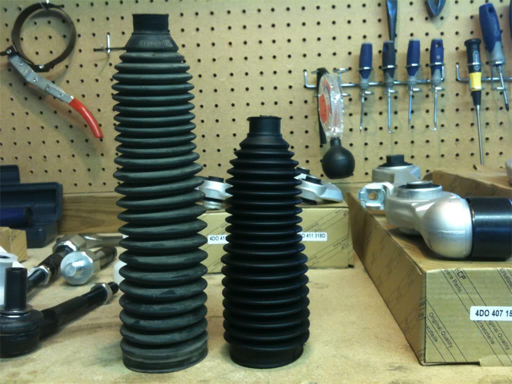
I reused the old 10" boot because it was still in good condition and I was out of patience by this point in the project.
Step 18. Install the new tie rod end assembly. You already know how to do this since you just took the old one off. When you put either a new boot onto the inner tie rod end, or use the old one, getting a new large clamp onto the inside part is going to be a PITA. You can either go out and buy a real hose clamp that uses a screw to tighten, or you may do like I did and use a large zip tie instead of a clamp. If you do use a zip tie, make sure to snug it down tight! And, make sure the boot is completely seated before tightening it down. You don't want any dirt or water to get into the boot.
One piece of advice I would give at this point is to add a light coat of anti-seize compound to the outer tie rod end threads, the part that screws into the inner tie rod end nut. This will help prevent having it get seized in there like mine was. And remember to put the plastic cover back on the car before you screw the outer tie rod end into the inner tie rod end.
If you plan on removing the spindle, don't install the new tie rod end assembly back into the spindle. You'll need the spindle to swing free when you're trying to get the axle out of the spindle. If you don't plan on removing the spindle, proceed with installation.
To install the inner tie rod end back into the spindle, you must first make sure that the valley, or notch in the nipple is lined up with the end of the spindle. If they are not lined up, there won't be enough room for the new pinch bolt to go all the way through the hole in the spindle. Sorry that I don't have a pic of this, but the way to move the nipple is by inserting a 10mm hex socket into the top of the nipple and then use a ratchet to turn the nipple until it's lined up.
Once that is lined up, go ahead and use the sledge hammer to tap the nipple all the way back into the spindle. You may then install the new pinch bolt and top bolt into the spindle. Remember to use some anti-seize compound on the pinch bolt! Tighten to 7NM, or 5 ft lbs.
Congratulations, you've got the tie rod end assemblies replaced! On to part 3: Replacing the upper control arms.
Part 3: Upper Arms
Alright, alright.
In part 1, we prepared your car for replacement. In part 2, we went through the steps to replace the inner and outer tie rod end assemblies.
In part 3, it's time to tackle those upper control arms, along with the dreaded "pinch bolt" that has been a source of many frustrated do-it-yourselfers. With a little bit of preparation, lots of mapp gas heat and plenty of violence, this job is going to be very rewarding.
Remember, always wear your safety goggles when doing any hammering, or when you're under the car.
Are you ready to have some fun? Let's do this!
Step 19. First things first. Begin by spraying a generous amount of PB Blaster onto the pinch bolt and it's nut, as well as in the gaps in the spindle. If you've read parts 1 & 2, you know that I've been telling you to do this for multiple days in advance in order for it to seep into the rust. 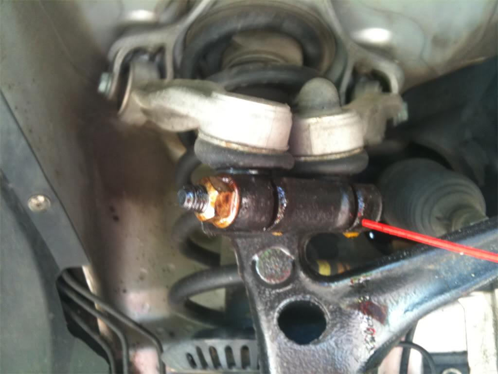
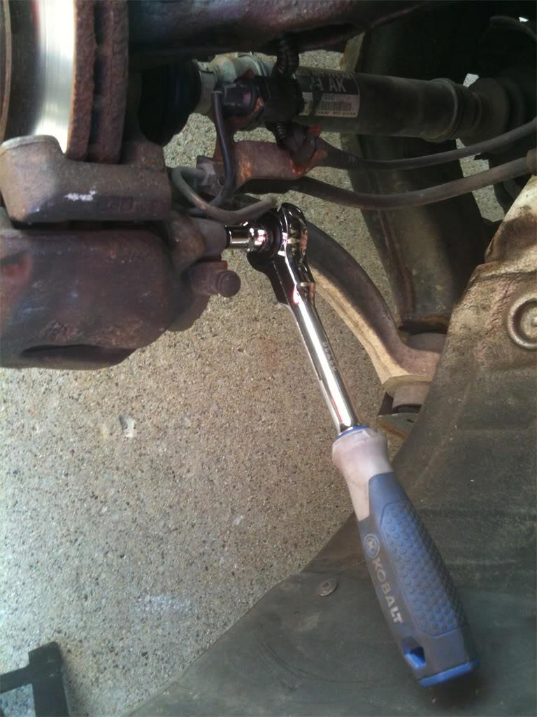
While the PB Blaster is soaking in, loosen up the bolts that connect the upper control arms to the shock housing. The bolt head and nut are 16mm. 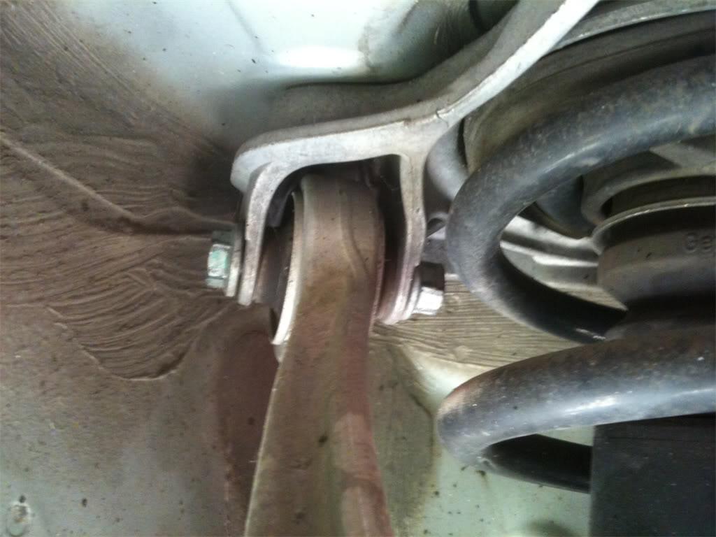
Step 20. Since the pinch bolt is usually the most difficult bolt to loosen and remove in the entire job, give yourself a better chance at removing it the first time by hitting it with some mapp gas heat. Grab your torch and heat up the pinch bolt area of the spindle, along with the nut. When it's good and hot, attach your 16mm socket to the pinch bolt nut, and your 16mm wrench to the bolt head on the other side. Turn counter-clockwise to loosen the bolt. Come on, baby, break loose for us! 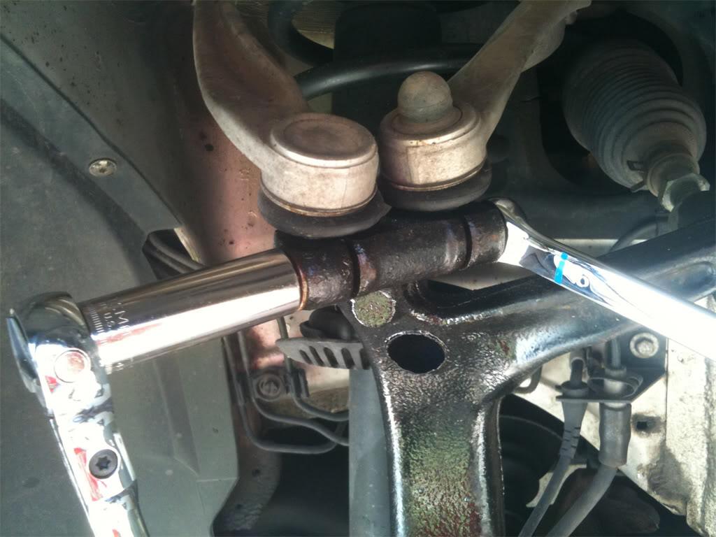
Step 21. If the gods of pinch bolts were kind to you, the nut should be loose now. Unscrew the nut until it's at the end of the pinch bolt, but still on the bolt. You're going to use this nut to hammer on with your 4lb sledge hammer to get the pinch bolt moving. Before you start hammering on the pinch bolt, shock the spindle by whacking it with the hammer where the pinch bolt lives.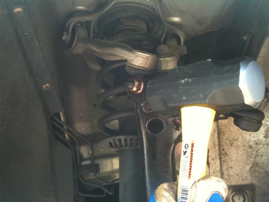
Then, take a large flat head screwdriver or small pry bar, and try to wedge it into the open spaces on the side of the spindle where the pinch bolt lives. After prying that apart for a bit, hit that area with the mapp gas torch again.
Now take the hammer, and hit that nut like there's no tomorrow. Heat & violence should win the game here. As shown in the pic below, the pinch bolt has started to move. Keep pounding away until the bolt is level with the hole in the spindle.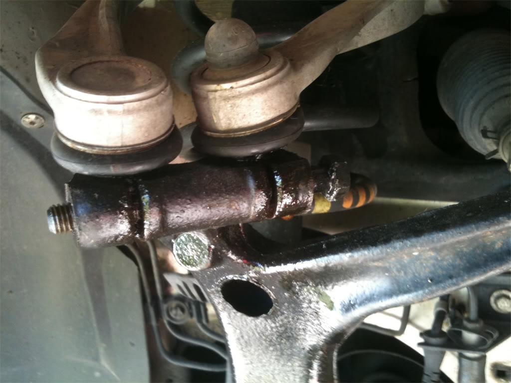
Next, take a punch and align it onto the pinch bolt.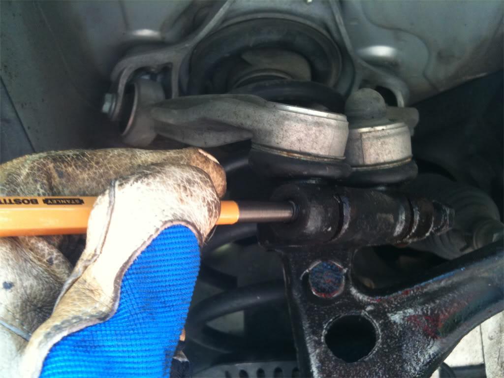
Hammer away at the punch until that pinch bolt is your beyotch and she pops out of the spindle and onto the floor. 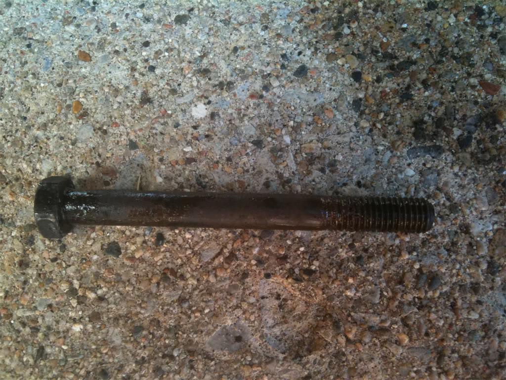
Now, if for some reason that pinch bolt is not out by this time, you either need to hit the gym to grow some muscles, or you didn't heat up the spindle enough. Try heating the spindle up again, and this time make it red hot!
If it still won't budge, then you want to look into borrowing a friend's air powered hammer in order to use superior brute force. If that doesn't work, then it's time to either drill it out, or buy a used spindle. From everything I've read, it's a bigger PITA to try to drill the pinch bolt out than it is to purchase a used spindle online and just replace it. If you do go the route of buying a used or new spindle, make sure to order one that already has a wheel bearing installed.
Step 22. Now that the pinch bolt is out, we can remove the control arm nipples from the spindle. You can either use the fancy tool from the Front End Service Kit that I showed you in part 2, or you can use the short screwdriver & hammer method and tap them out this way. As a review, here is the pic from the tie rod end removal showing the tool I used.
Here's a pic or the upper control arms completely freed from the spindle. Notice the grooves in the pic. When you install the new control arms, these grooves must line up with where the pinch bolt is going to pass through them in the spindle, otherwise the pinch bolt won't be able to travel through the entire spindle. So when you pound the nipples back into the spindle, make sure to get them down far enough so that the grooves are lined up in the hole. 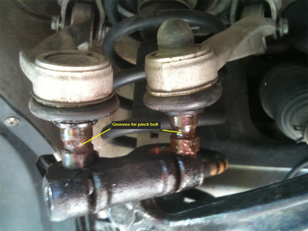
Step 23. At this point, you can remove the upper front control arm by unscrewing the bolt that you loosed before. You won't be able to remove the upper rear control arm, though, because there's not enough room to get the bolt out of the shock housing. In step 24, you're going to remove the shock housing from the car, allowing you ease of removal of that last control arm, and easy installation of both new upper control arms.
Step 24. Open your hood and look for three 16mm bolts that hold the shock tower to the car. On the passenger side, if you have the 2.8L V6 engine like I do, you'll have to remove
this cover...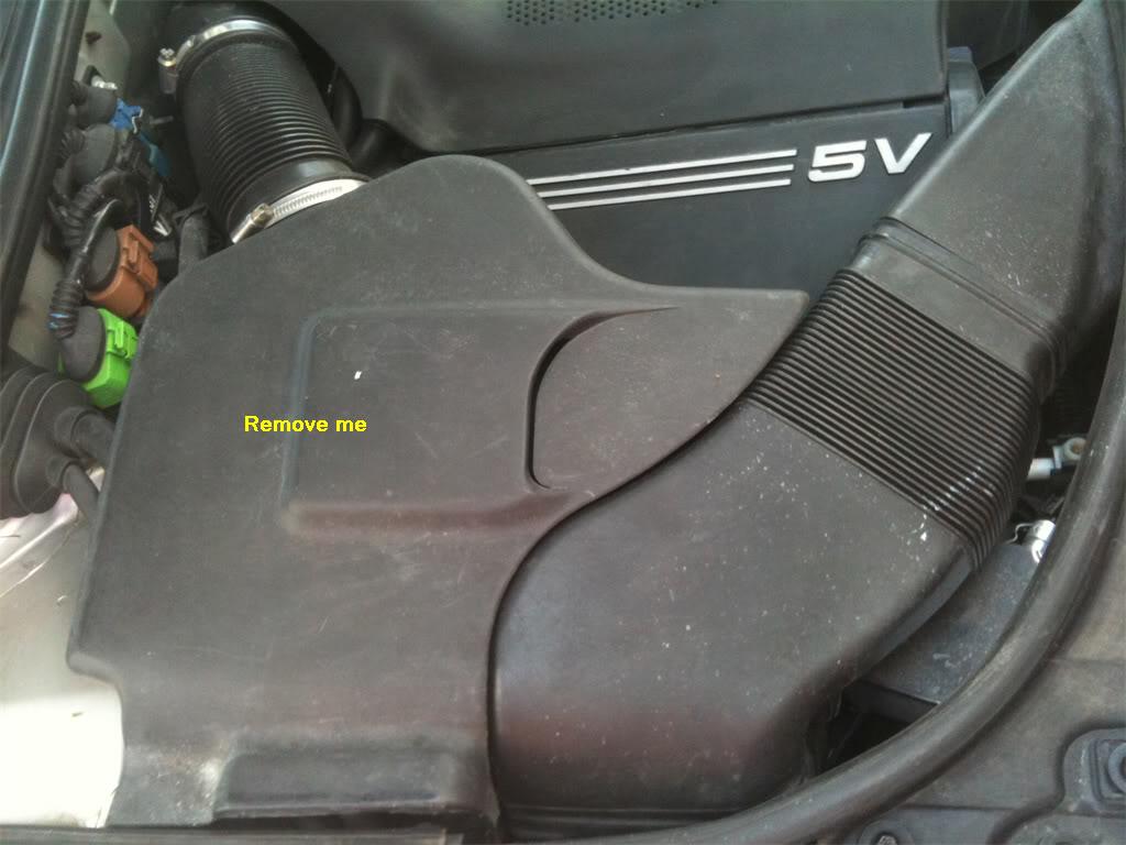
and this strip of rubber and cover.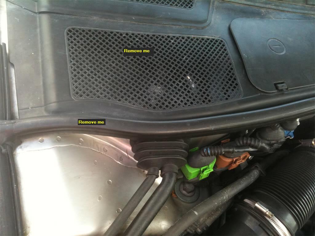
Now, we see our three bolts.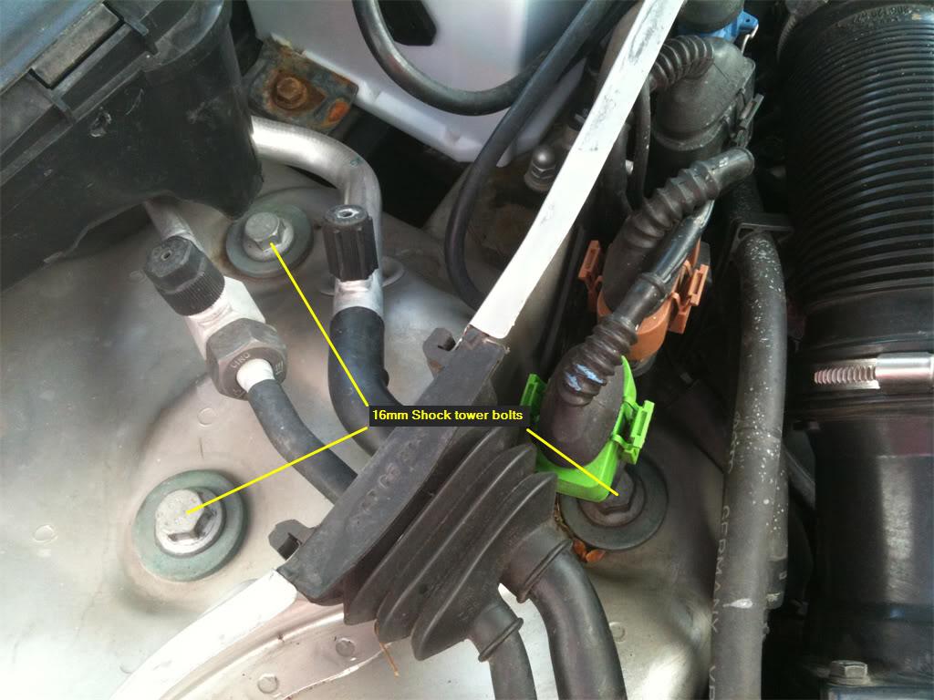
That little green module is in the way of one of the bolts. No problem, you can just wiggle it forward to free it from the two little plastic arms holding it in place. When free, move it to the side. 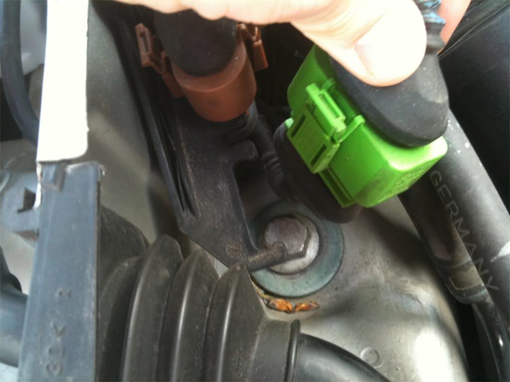
Now you may proceed to remove the bolts using a 16mm socket, or a 16mm box end wrench. Since I'm lazy by nature, instead of removing the cabin air filter cover to get at the bolt closest to the firewall, I opted to use a 16mm box end wrench on it instead of a socket.
Step 25. One last thing to do before you can remove the entire shock tower. You need to remove the strut bolt from the lower front control arm.
The 18mm nut on mine looked pretty rusty, so I hit it with some mapp gas heat before I attempted to remove it. 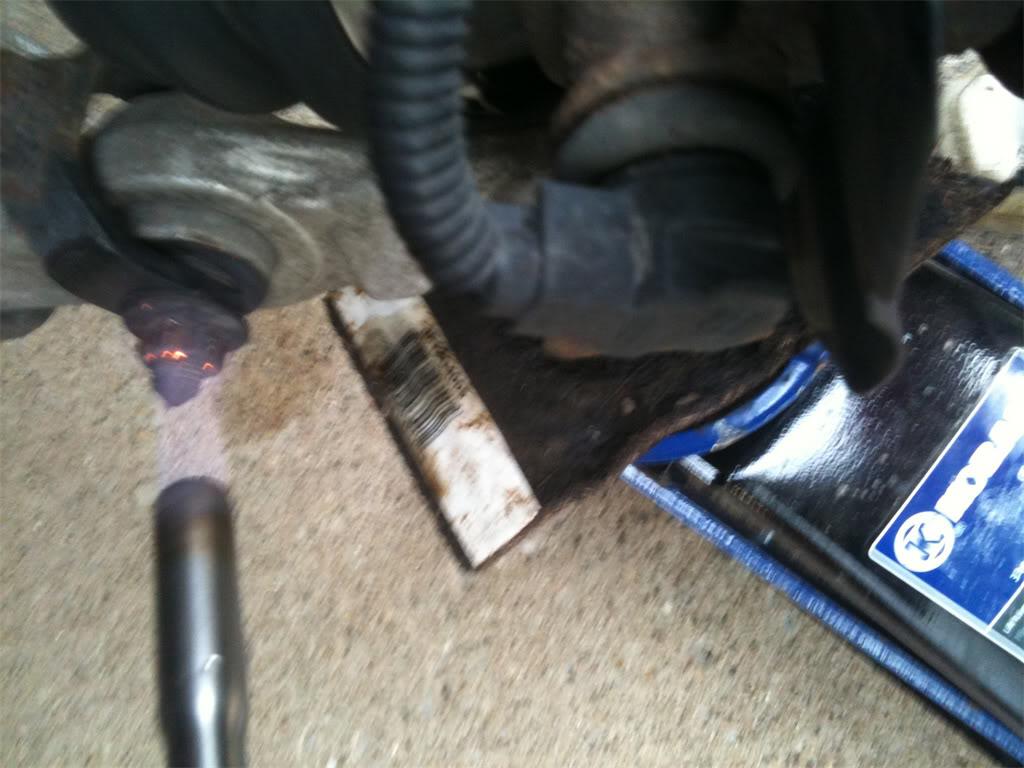
Next, put the socket on the nut, and an 18mm box end wrench on the bolt head on the other side of the control arm, and remove it.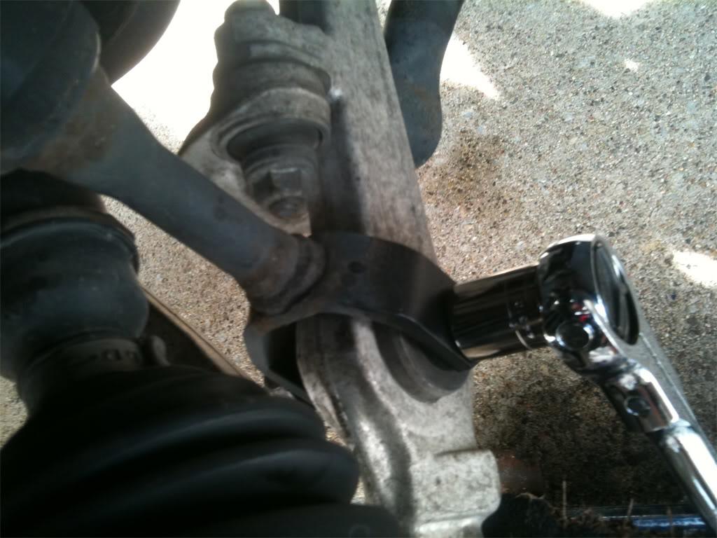
Step 26. Remove the entire shock tower and place it on the ground. From here, proceed to unbolt the remaining upper control arm.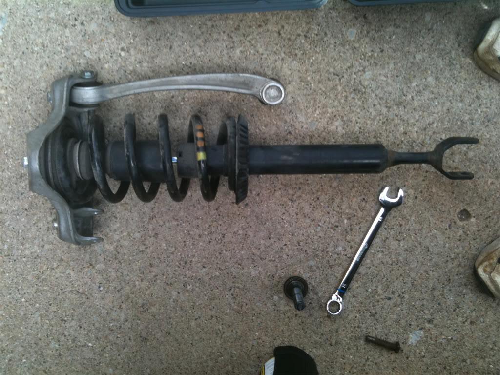
On the passenger side, I had no trouble, since the bolt head was pointing toward the front of the vehicle. But on the driver's side, the bolt head was point toward the rear of the vehicle, which means that the bolt ran into the lower rear control arm and before it was out of the lower front control arm. Here's a pic of this dilemma.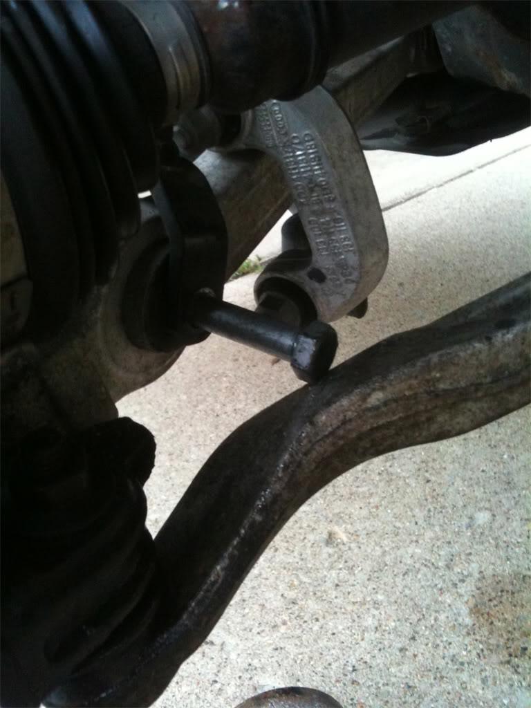
In my case, I had to wait to remove this bolt until I dropped the lower rear control arm out of the spindle. I won't spend time on that in this thread, as the lower control arms will be dealt with in part 4. Maybe I was just unlucky and your bolt head will point toward the front of the vehicle on both sides.
Alright, we're done with part 3! Installing the upper control arms is a snap, so I won't spend any time talking about it in a thread as large as this one is already.
In our final installment, part 4, you are going to tackle the lower control arms. I don't want to give too many surprises away, but there is one PITA when dealing with the passenger side lower rear control arm. But other than that, it's not bad at all.
Part 4: Lower Control Arms
In the final part of this series, you will remove and replace the lower control arms and tie rod ends.
We're in the home stretch, so let's do it!
Way back in part 1, I gave you the option of leaving the wheel bearing housing(aka "the spindle") alone, or removing it. If you decided that you wanted to remove it to replace the front wheel bearings, or if you just want more room to maneuver while changing everything else out, continue to step 27. Those of you who decided to leave the spindle alone can skip ahead to step 29.
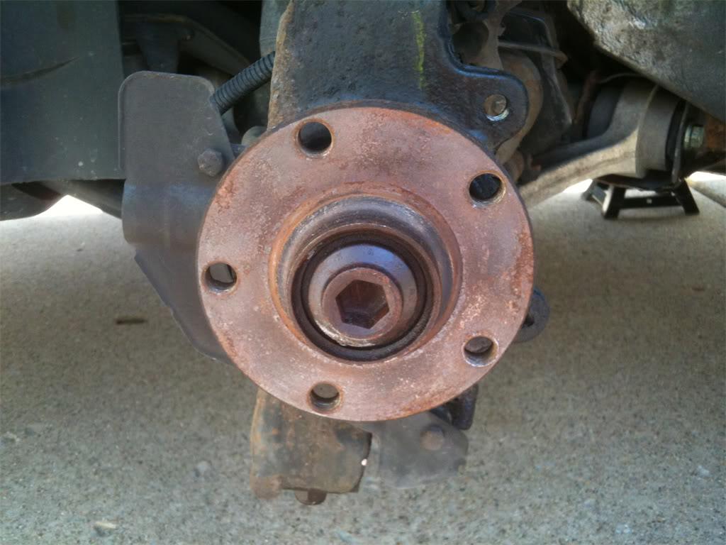
Step 27. To remove the axle from the spindle, turn the axle bolt counter clockwise a few turns, then push it in with both thumbs while holding onto the spindle with the rest of your fingers. Using this method, continue to work the axle out of the housing until you can no longer move the axle with the axle bolt. You may then remove the axle bolt and place it somewhere where it won't get dirty or contaminated with anything.
Looking into the hole where the axle bolt was, this is what we see: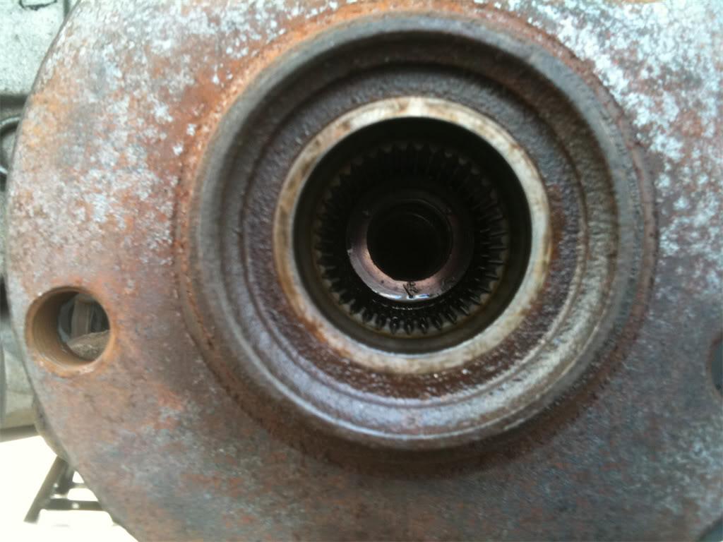
Step 28. Since the upper control arms and tie rod ends are out of the spindle now, it will be fairly easy to move the spindle around. You might be able to wiggle the axle out of the spindle by also pulling the spindle forward at the same time. If this works, this is what the axle will look like after it's out of the spindle. Once out of the spindle, you can swing the axle to either side in order to work on the lower control arms. 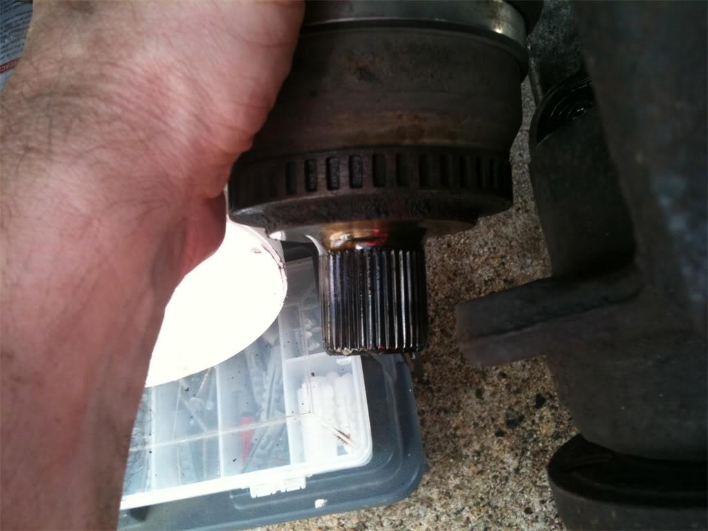
If you weren't able to get the axle out using that method, then just go ahead and proceed with removing the lower control arms and sway bar links. You'll be able to get the axle out without difficulties with those disconnected.
Step 29. Remove the belly pan that protects the oil pan and front part of the car from rocks and debris on the road. The belly pan is held on by approximately 10 fasteners and screws. Here's a view of the underside of the car that includes the lower front control arm and a belly pan fastener.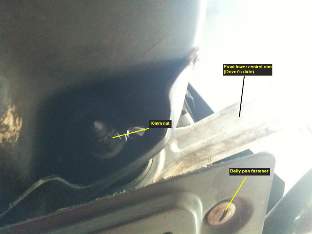
Step 30. Loosen the lower front and rear control arm bolts that are attached to the sub frame first. This is very straight-forward, and shouldn't be a problem. Both control arms use 18mm bolts.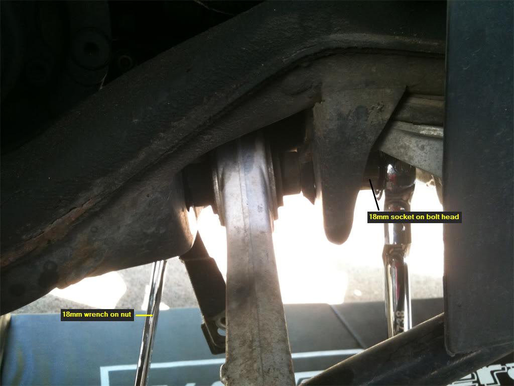
Step 31. Next, remove the sway bar links that attach to the lower front control arm and the sway bar. The bolts and nuts are 16mm. 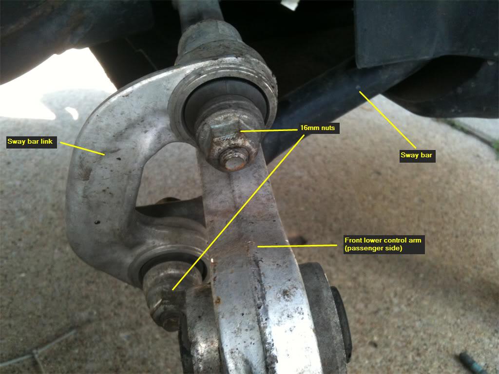
Step 32. Now, you're going to remove the 18mm nuts from both the front and rear lower control arms. As this picture shows, the nut for the rear control arm is on the top of the spindle.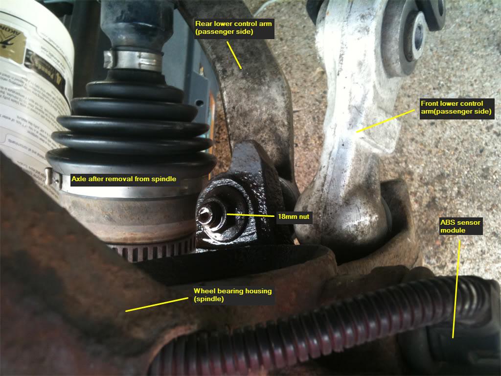
And this pic shows that the nut for the front control arm is on the bottom of the spindle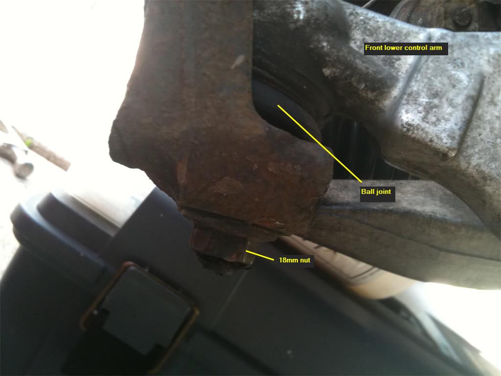
Those of you who removed the axle from the spindle will benefit from having clear access to the rear control arm bolt, and may use a socket on this one. If you left the spindle alone, you will probably have to use an 18mm wrench to remove the nut.
Step 33. With the nut removed, you can now pop the ball joints of both control arms out of the spindle. To accomplish this, I used one of those handy tools from the front end service kit that I purchased for this job. By using this tool, I had both ball joints out of the spindle in 5 minutes. When the ball joints pop out, there will be a loud SNAP! Don't worry, you didn't break anything. 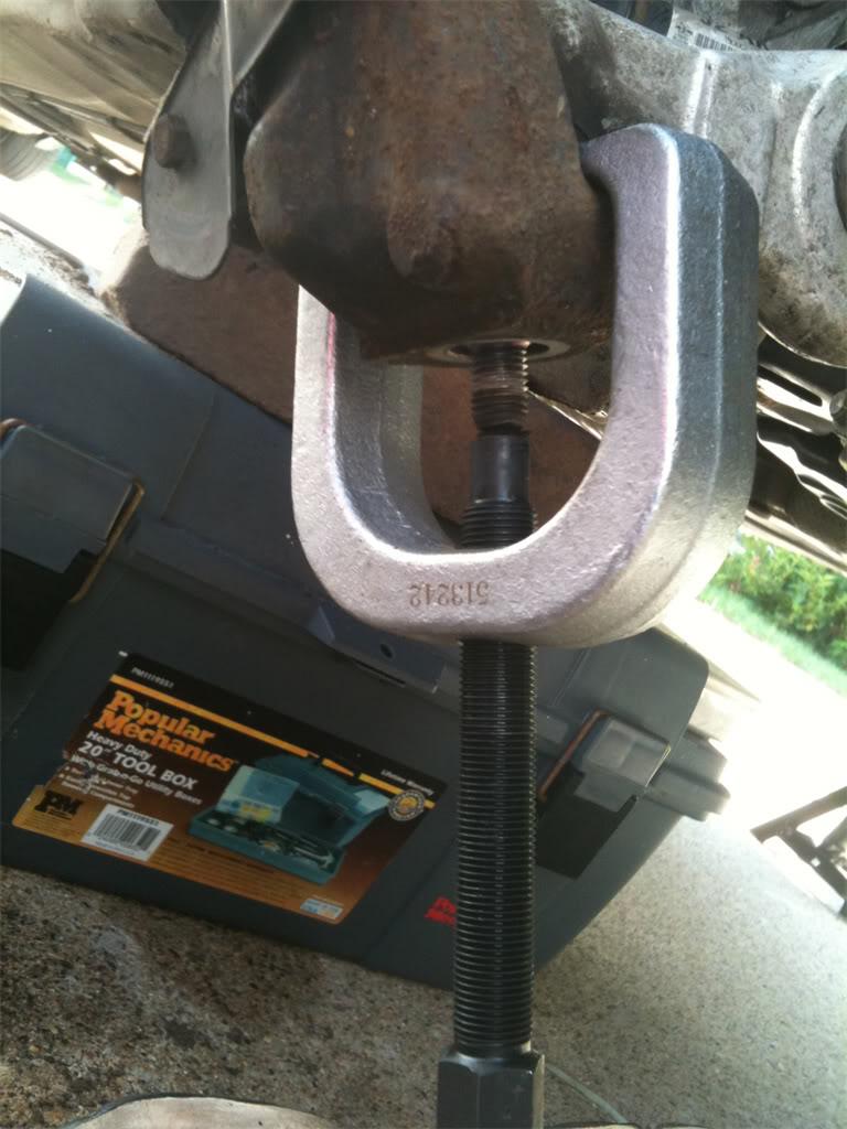
With the ball joints out of the spindle, you may either set the spindle to the side, like I did, or remove it completely out of the picture by removing the ABS brake sensor. I've heard that the ABS sensor just pulls out of the spindle, and then you can pull it through the spindle. The spindle can be removed completely now.
In my case, my ABS sensors looked really rusty, and didn't pull off easily when I tugged on them. So, I ended up deciding not to press my luck and take the chance that I would break them. I just left the ABS sensor alone and carefully laid the spindle down off to the side, supported by a tool box. 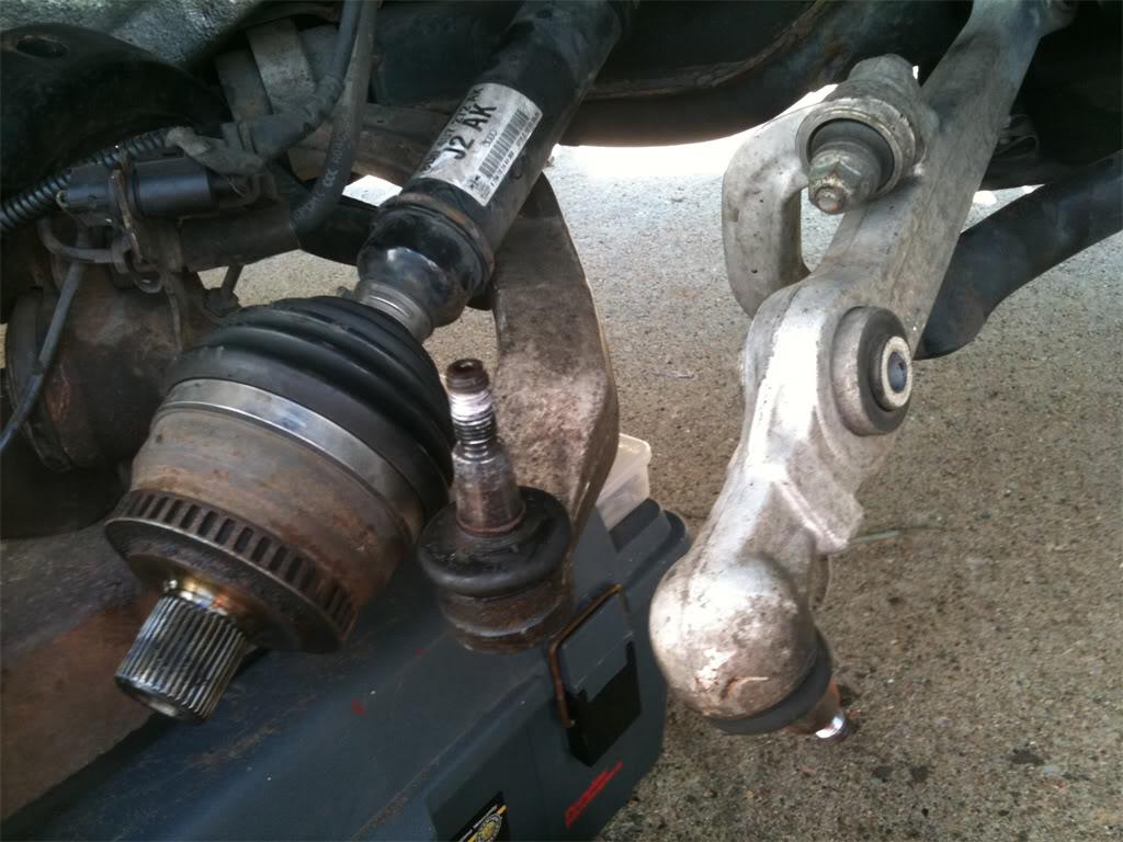
Step 34. Ok, go ahead and finish removing the bolts from the lower front control arms. They will be easy to remove. The bolts are long, but can be threaded through the chassis and removed without any problems.
Step 35. I wish the same could be said of the bolts on the lower rear control arms. Getting these out will require a few extra steps, and the passenger side is a bonafide PITA to get out. Let's hope that the Audi engineer who thought up this design is now asking people "Would you like fries with that" at work instead of designing automobiles.
I'll concentrate on the passenger side, because once you can do this side, the driver's side will seem like child's play. First, a look at the problem and the obstacles. 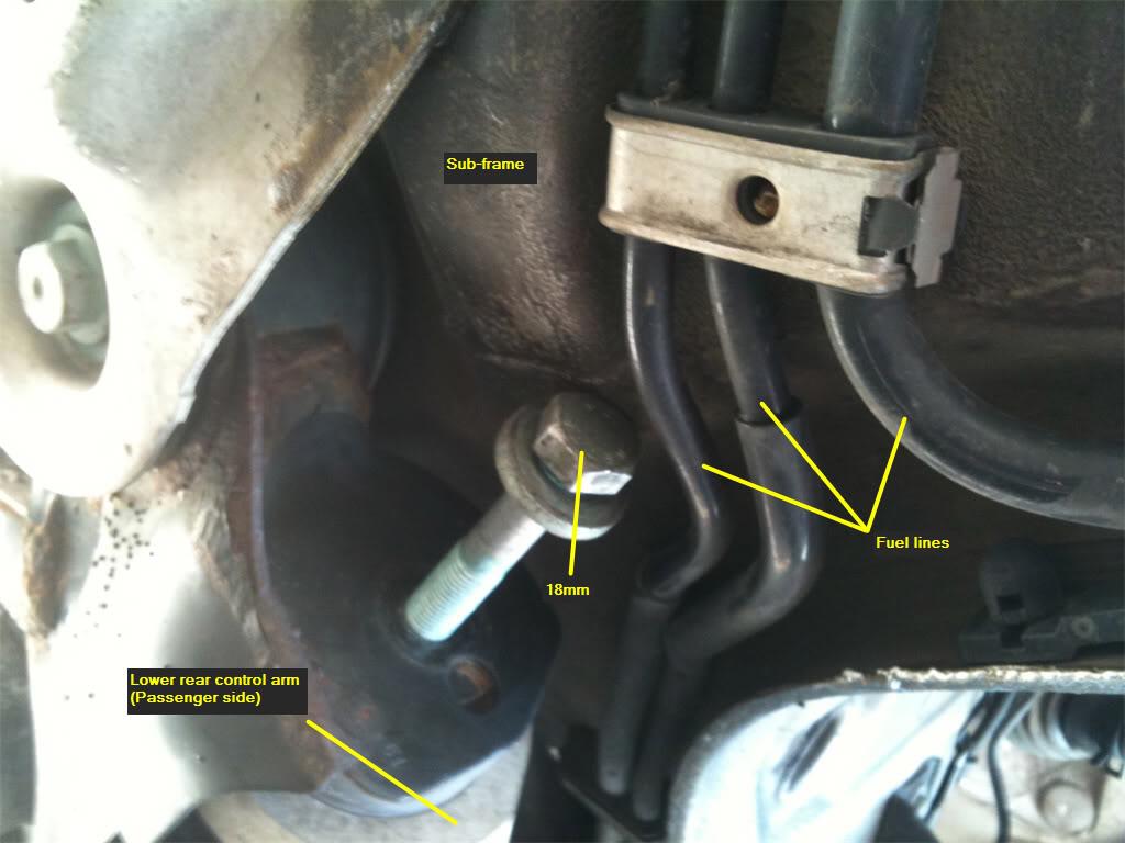
As you can see, you can't unscrew the bolt out far enough to get it out without hitting the subframe and the three fuel lines. To solve this problem, the first thing you'll do is loosen the 18mm bolt holding the subframe shield to the subframe. Loosen it about one inch. 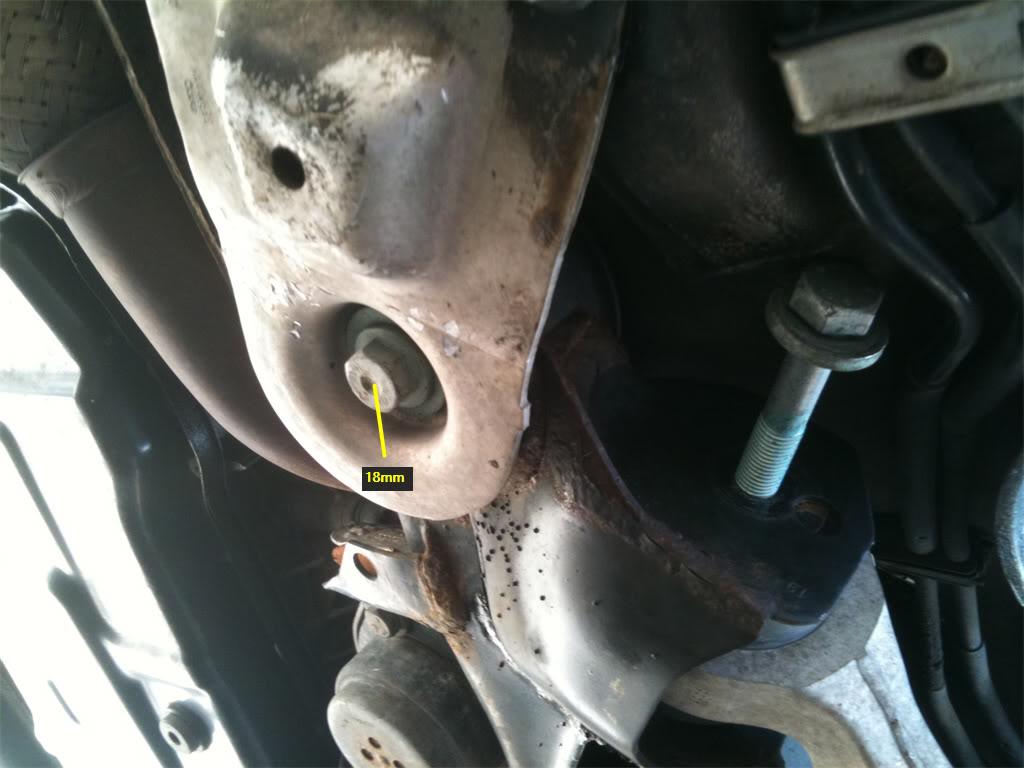
Next, pry the clip down that secures the three fuel lines. This will allow the clip to pop open. I used a flat head screwdriver to accomplish this. Once free, move the fuel lines out of the way. Using a pry bar, pull the subframe down while at the same time wiggling the bolt past the subframe and between the fuel lines. This part takes a little bit of experimenting with, but you'll eventually get it.
And here is the freed bolt, courtesy of some stupid engineering, and your strenuous efforts.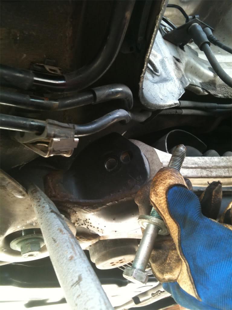
Step 36. Whew, now you can go ahead and remove the driver's side lower rear control arm. Same method, but no fuel lines to worry about. This will be much easier than the passenger side.
Congrats! You are almost done. All you have to do is install the new control arms and tie rod ends, if you were one who chose to remove the spindle. If you left the spindle alone, you probably already installed the new tie rod ends and the upper control arms.
Another word of caution. Since putting together the suspension is sort of like a jigsaw puzzle, it's best to leave all the bolts and nuts loose until you get everything together.
Before tightening the bolts and nuts down tight, using the torque specs below, it is critical that you apply load to the suspension first. If you tighten the control arms and tie rod ends without having load on the suspension, you will wear these parts out prematurely, and will have to do this job all over again soon!
To put the suspension under load, simply place your jack under the lower rear control arm's ball joint, and jack up the spindle until it's at a level with where it normally sits when the car is on it's wheels on the ground. You don't have to be perfect with this step, just eyeball it.
Here are the torque specs for the control arms:
Upper front - 50 Nm + 1/4 turn into mounting bracket
Upper rear - 50Nm + 1/4 turn into mounting bracket
Upper pinch bolt - 40 Nm
Lower front - 80 Nm + 1/4 turn into subframe
Lower rear - 90 Nm +1/4 turn into subframe
Lower control arms into the spindle - 100 Nm
Shock tower assembly bolts - 75 Nm
Lower nut and bolt into control arm - 90 Nm
Lower connection to the sway bar - 45 Nm
Upper connection into the control arm - 40 Nm + 1/4 turn
Rear Sub Frame, Large Bolt 110 Nm + 1/4 turn
Axle bolt - 200 Nm(My torque wrench doesn't go this high, so I just put my breaker bar with the pipe on it, and torqued it for all I was worth).
When you are all done with the job, make sure you take your car to the dealer or an alignment shop and get a four-wheel alignment. If you decide to be cheap and ignore this vital step, you could be looking at having to purchase new tires sooner than you would have to with a well-aligned car.
And now, my friends, it's time for the final and most satisfying step. As you are standing back and admiring your work, go to the fridge and get yourself a few of these, as a reward for a job well done. You've earned it! 
Wow great detail!
Posted by Diggymart on 5/11/20 @ 1:44:24 PM