You must be logged in to rate content!
4 minute read
Temp Gauge Modifications
Compliments of ACW @ www.ls1tech.com
Temp Gauge Mod
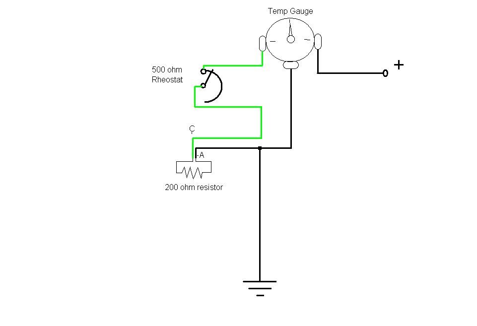
1.Take a 200 ohm resistor and unplug the temp sensor, and hook the resistor to terminals 'A' and 'B' of the plug. Turn the ignition on and read the temp gauge, it should read about 210° F. (maybe a little over, but memorize where the needle is)
2.Get a temp sensor from a 98 F-body
3.Get a temp sensor terminal plug from a 98 F-body
4.Hook a 20 Gage wire to terminal 'C' of the new sensor plug. (Terminal 'A' is sensor ground, and 'B' is sensor signal to PCM.)
5.Pull the two wires from terminals 'A' and 'B' from the old sensor plug, and replace them into terminals 'A' and 'B' of the new sensor plug. (Wires go from terminal 'A' to 'A', and 'B' to 'B')
6.Place new temp sensor into the engine head.
7.Pull the Gauge cluster out.
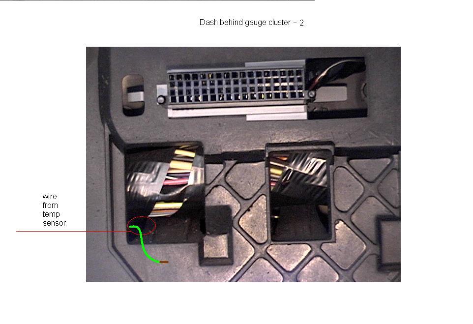
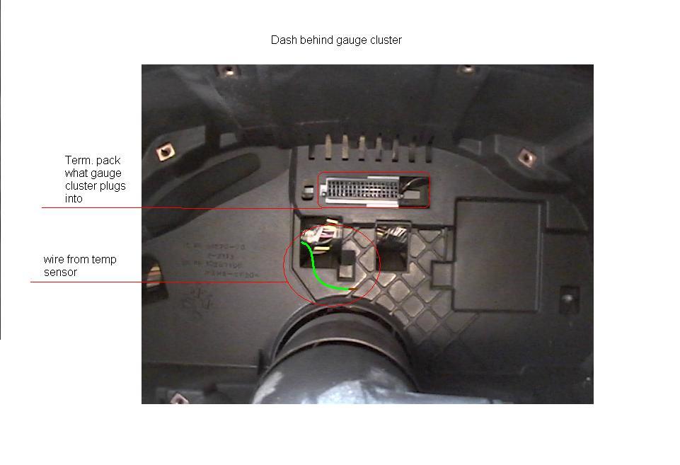
8.Run the other end of the new wire from terminal 'C' through the fire wall and into the cab, run the wire behind the dash and into a hole behind where the gauge cluster goes, and put an insulated female connector plug on the wire.
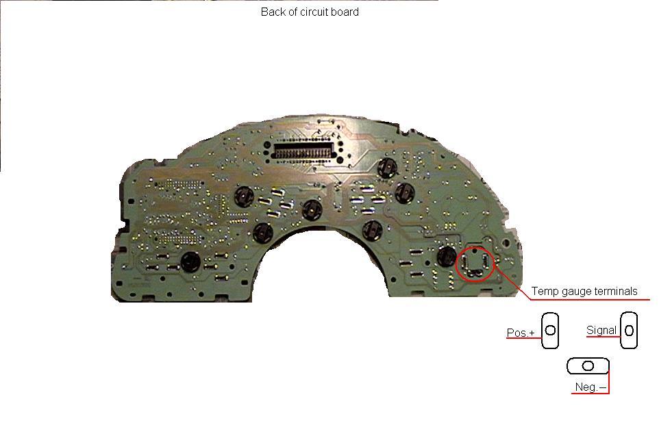
9.Cut another length of wire and put an insulated male plug on one end, and the other end gets soldered to the gauge cluster circuit board.
10.Take out the two torx screws that hold the back cover on, and pull the back cover off.
11.Take out the one torx scre by the plug pack terminals that's holding the circuit board on. Very carefully pull the circuit board off. (You need to go around the edges and gently pull up with your fingers while unsnapping the tabs.)
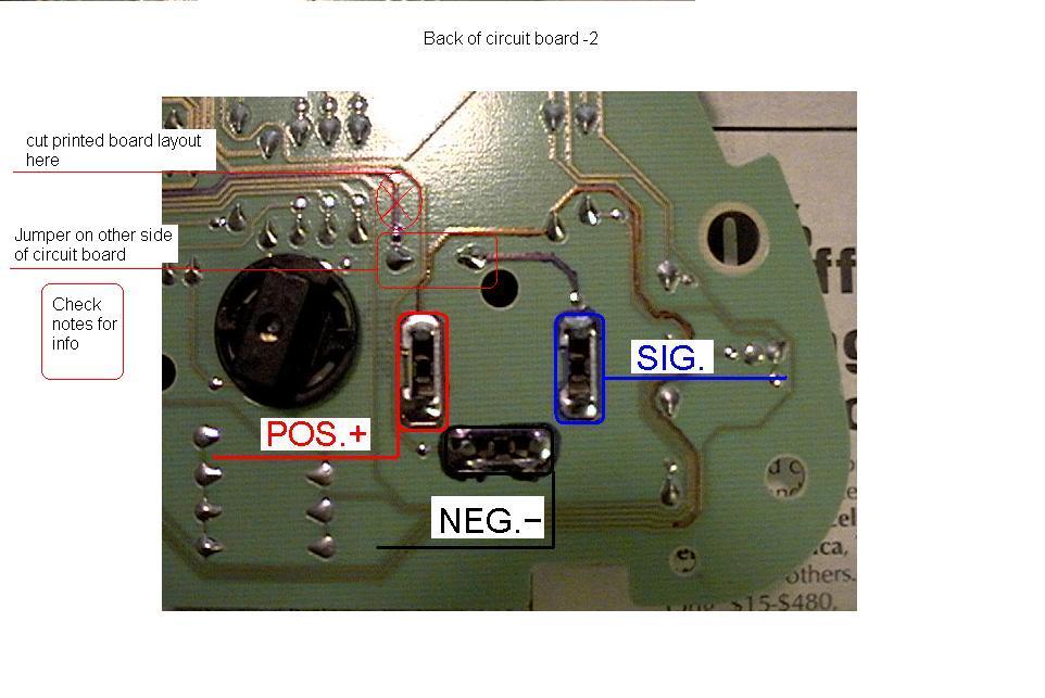
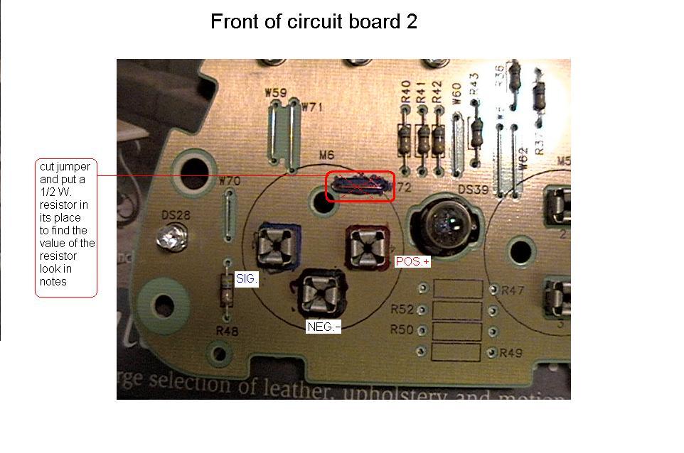
12.Take a razor and on the back of the circuit board (the pic shows where), make a cut next to the jumper solder joint on the printed circuit layout, and make another cut about 1/8 of an inch down from the first cut on the printed circuit layout so that a 1/8 inch piece of the printed circuit layout can be pulled off.
13.De-solder the jumper, and replace it with a resistor that will calibrate the temp gauge. (We will figure out the resistor's value next.)
14.Take the end of the wire that is to be soldered, and solder it into the solder joint that you cut the piece of layout out and pulled the jumper out.
15.Take a 5K.Ohm rheostat and hook it between the new wires coming from the dash and the gauge cluster, with the 200 ohms resistor hooked into terminals 'A' and 'C' of the sensor plug. Turn the ignition on, and turn the rheostat till the gauge reads what it did the first time you read the gauge with the 200 ohm resistor in the sensor plug.
16.Read the resistance of the rheostat, and that is the value of resistor to solder in the place of the jumper you took out earlier.
17.Put everything back together and test.
18.AutoTap or some type of scan tool would verify the accuracy of the temperature gauge after the mod.