You must be logged in to rate content!
9 minute read
Install headlight relays - A4 B5 1.8T
Compliments of BaseDrifter @ www.audiforums.com
Audi has done a lot of great work and a lot of us love our B5s. Unfortunately Audi's design of the B5 headlight switch was not so stellar.
No relays were used and the full current draw of both headlights passes through the small plastic contact of the headlight switch. Over time this can cause the plastic to heat up and melt, when the contact housing melts it pulls the metal contact away from the switch which results in the loss of both headlights and fog lights.
The solution is to install the relays that Audi should have from the factory. There are a few threads about installing headlight relays, however most involve installing the relays some place under the hood. This never appealed to me both for aesthetic reasons and for the simplicity of wiring. Instead I chose to install two OEM plugs and relays into the factory relay panel and wire them through the fuse box. I harvested the plugs and relays from a car at a pick n pull for a few dollars.
It is always a good idea to have an understanding of the circuitry before you start cutting into the factory harness. Make sure you know what wire you are cutting, where it goes, where it comes from, and why you are cutting it. Could you repair this cut if you make a mistake? (Don't clip a wire at the base of the pin, you won't be able to resolder the wire if you made a mistake.)
The headlight circuit is pretty straight forward.
We'll pick up the circuit as power flows into the headlight switch from the starter switch.
1. Switched power from the starter switch enters headlight switch at pin 2 through a yellow/black wire.
2. When the headlight switch is turned into the on position (2 clicks up) power flows out from pin 8 into a two yellow wires (it will split into four, but we are only concerned with two.)
3. From the headlight switch power flows into the fuse panel. Fuse 20 (10A) is for the passenger side low beam, fuse 21 (10A) is for the driver's low beam. This is where we will pick up the signal and reroute it to the relays. From here on out we have two circuits, one for each headlight.
On the passenger's side, the white/yellow wire coming off the other side of the fuse goes directly to the low beam. On the driver's side, it is the black/yellow wire that goes to the low beam.
We want to keep the stock fuses in place, so we will be tapping into the wires after the fuse, white/yellow and black/yellow. The advantage of splicing into the wires here is that both wires are in the same location. The harness splits further towards the front of the car and you may be having to trace the harness, cut into it, pull wire out...not fun. There is room to work in the fuse box area.
Alright now time for some pictures and instruction.
1. Start by gathering the relays and plugs you will need. While it would be possible to install a single relay for both headlights, it would be wise to keep the circuits separate and run each light off its own relay. I found a nifty double relay plug that works great for this, though there is no reason you can't use two individual plugs.
Here is the plug I got.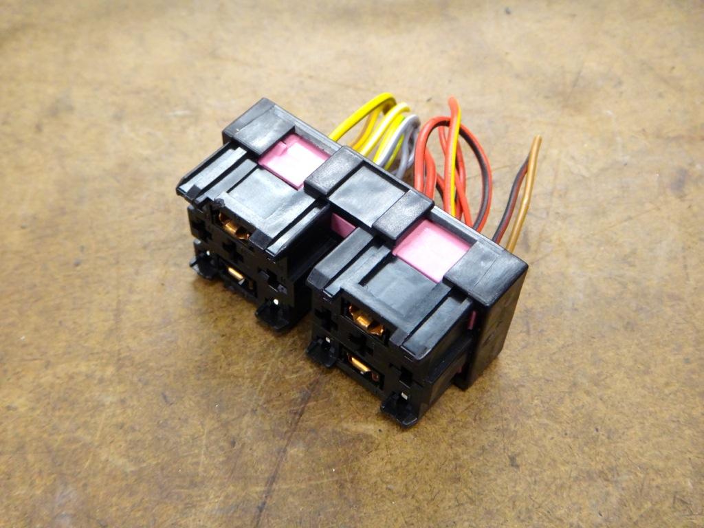
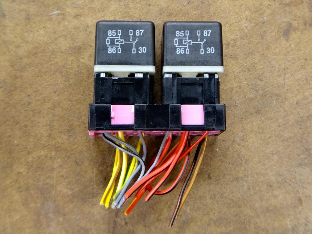
With relays.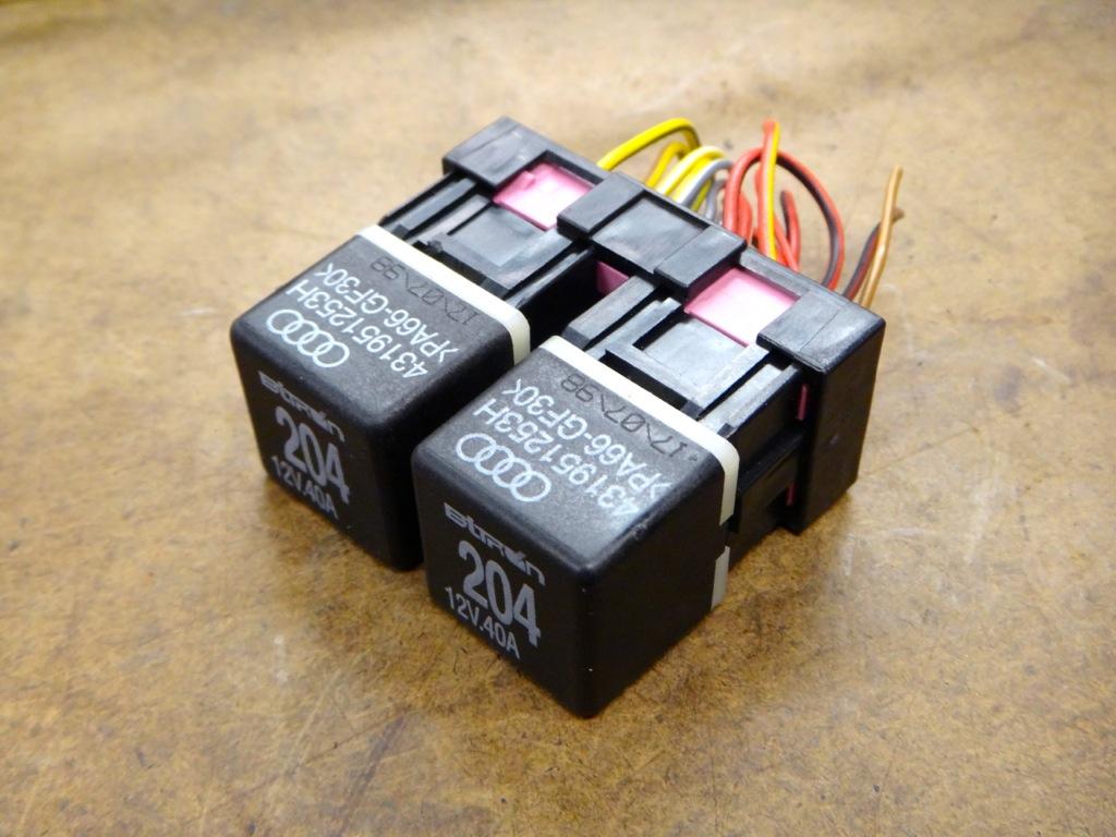
We will only be using four wires per relay, so we can remove the majority of the pins in the plug. Removing the pins can be a headache. Each pin has two locking tabs on the top and bottom, both must be depressed to pull the pin out. I made two "pokers" out of a piece of flatstock brass. Once you get the hang of it they go easy, you'll be cursing at the first few though.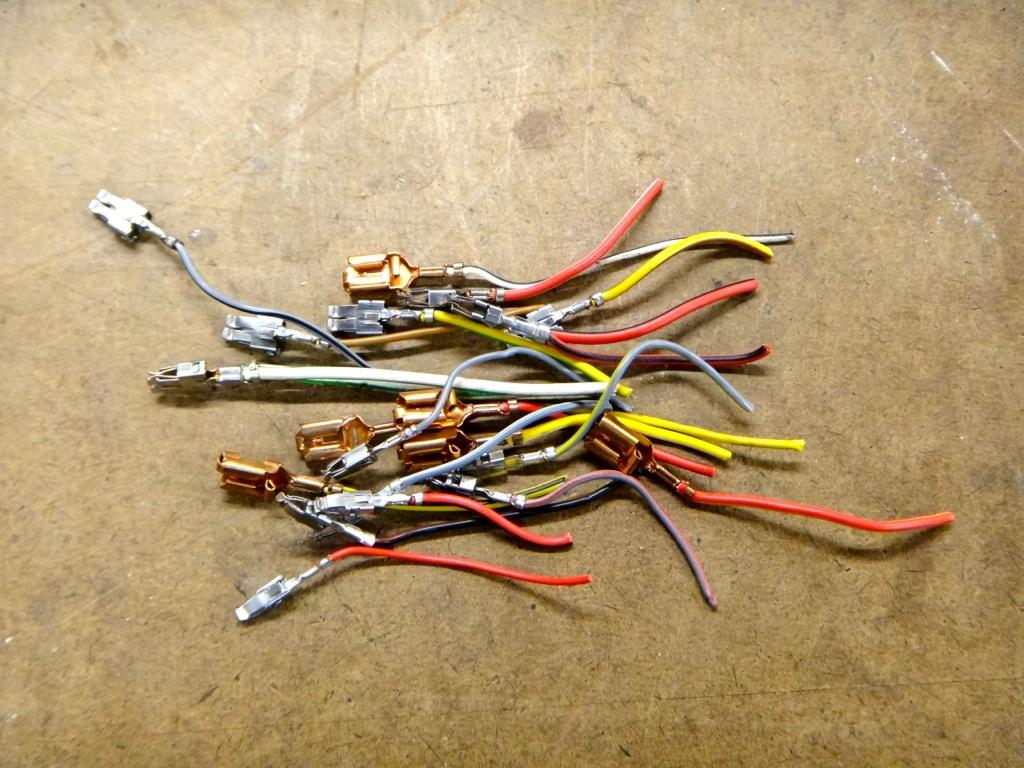
Empty plug.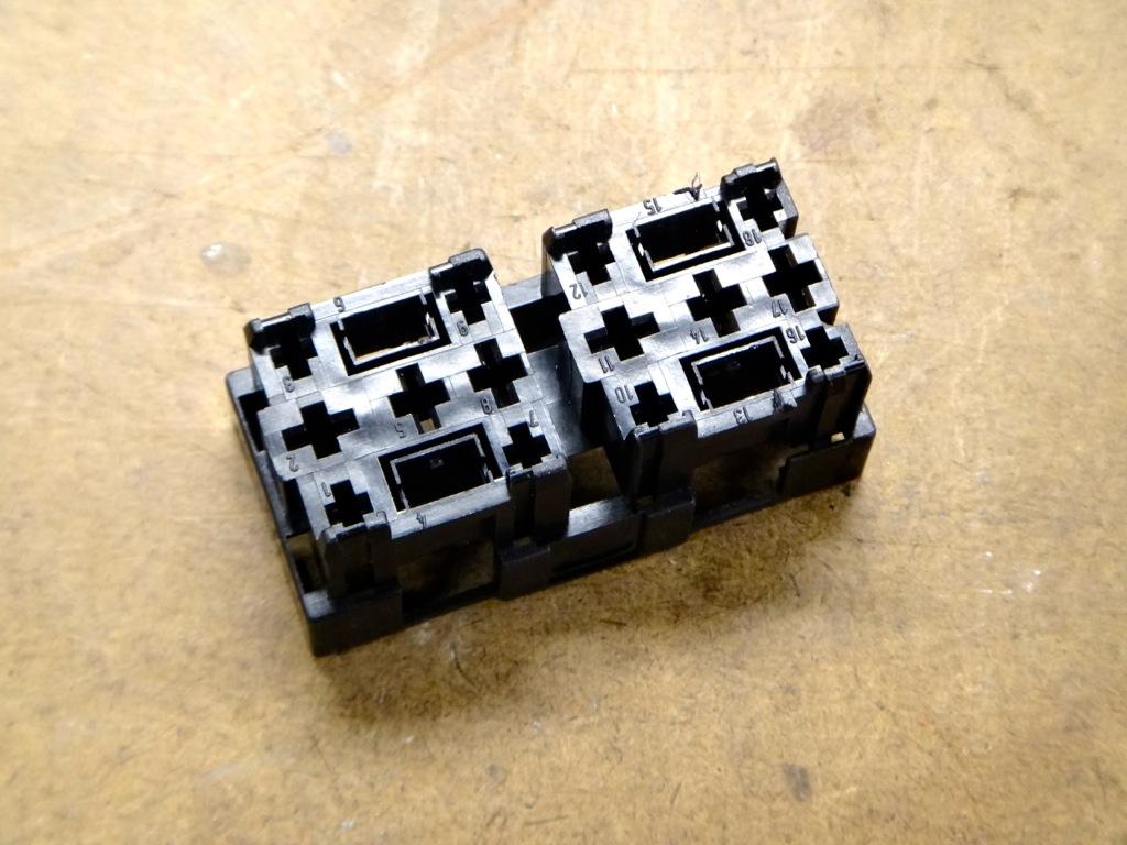
2. Next you'll want to remove the knee bolster, it is held in place with 3 8mm bolts hidden behind cover panels. Make sure to disconnect the VAG COM hookup before pulling the cover away. Disconnect the floor light if you have one as well.
3. Remove the fuse box from it's cage. It is secured with two 8mm bolts and two clips. Remove the bolts, pop the clips, and work the fusebox downwards until it is clear of the metal frame. Two clips on the side of the fusebox keep it closed, pop those clips open. You'll see the wires we are interested in at the top outermost corner, nice and easy to get to!
Here you can see the bolster removed and fuse box pulled down. (Don't worry about the missing steering wheel and cluster, those were removed for another project and aren't necessary to remove for this project.)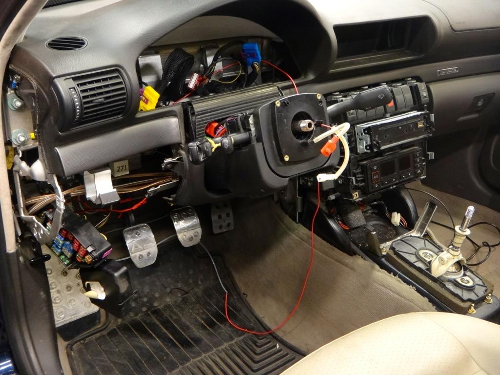
4. With the fusebox pulled down and the cover popped open you should be able to see the wires we are looking for. Make sure you have the correct wires. One white/yellow and one black/yellow. Cut them about halfway from the fuse to where they enter the harness. Leave enough room to do your soldering.
5. Take some measurements/estimates of length and start wiring up the relay wiring harness. I actually harvested some OEM white/yellow and black/yellow wire from a donor car to complete the wiring harness. Any color of the proper gauge may be used. For cleanliness and ease of problem solving later, sticking to the same color is highly recommended. Use electrical tape on some yellow wire if you can't get OEM wiring.
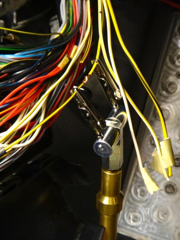
Here I have soldered on new wire to the pins for the harness.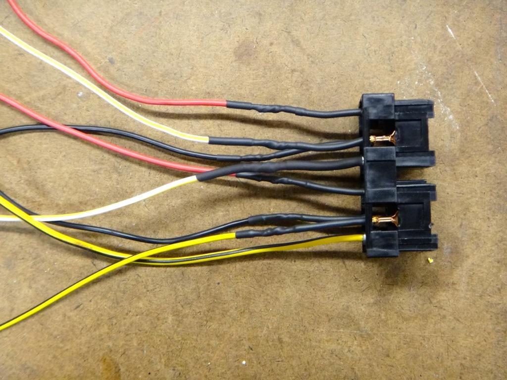
I guess I should talk about wiring the relay now. The relay has 4 contacts. A signal input, a power input, a power output, and a ground.
- Pin 85 is the ground.
- Pin 86 is the signal input
- Pin 30 is the power input
- Pin 87 is the power output.
In our case, we are taking the input from the headlight switch to trigger the relay to send power out to the headlights. So pin 86 receives a signal from the headlight switch to close the contact between pin 30 and pin 87, sending power to the headlight.
Here is my finished harness. The two red wires go to a fused power distribution block hooked up to the switched 75x post under the dash. The two black wires are the grounds, and the two yellow/white and two yellow/black wires are the inputs and outputs for each light.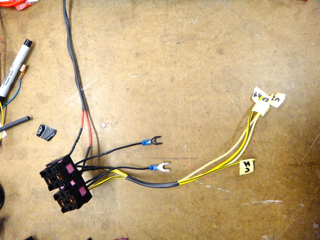
Here are the plugs installed into the relay panel. I chose the two slots at the left most position since it is closest to the fuse box.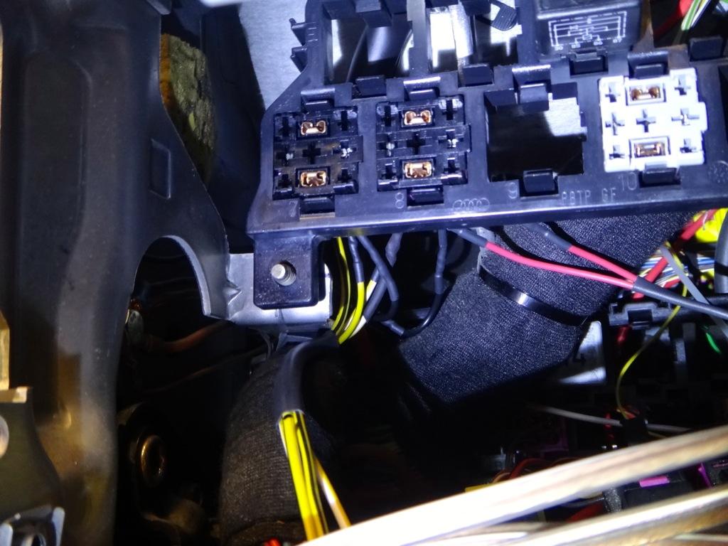
Relays installed.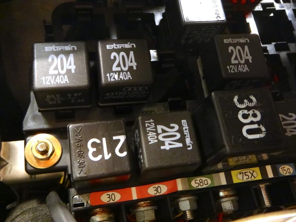
6. Once you are sure you have the proper wire lengths, you can start to solder the harness in place.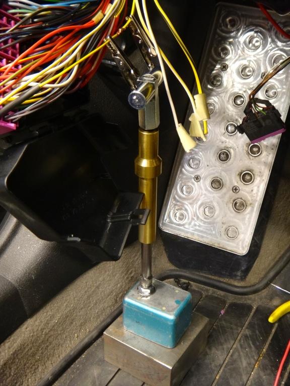
A little hard to see, but here are the final connections spliced into place.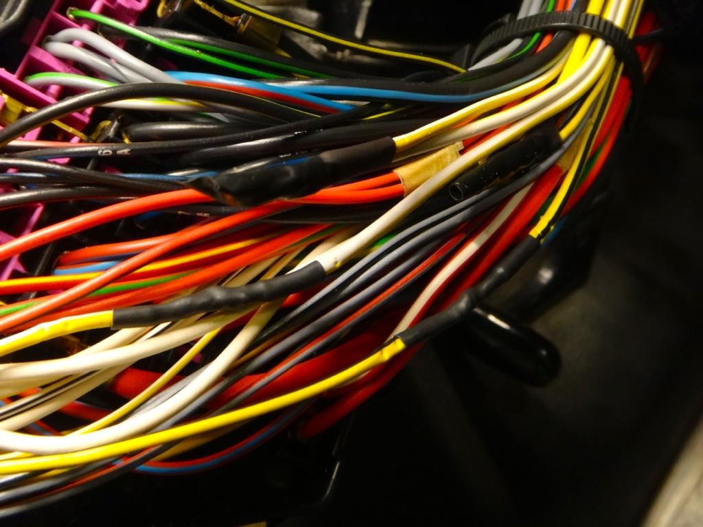
Directly to the left of the relay panel is a factory grounding location. I ran both relays over to this ground.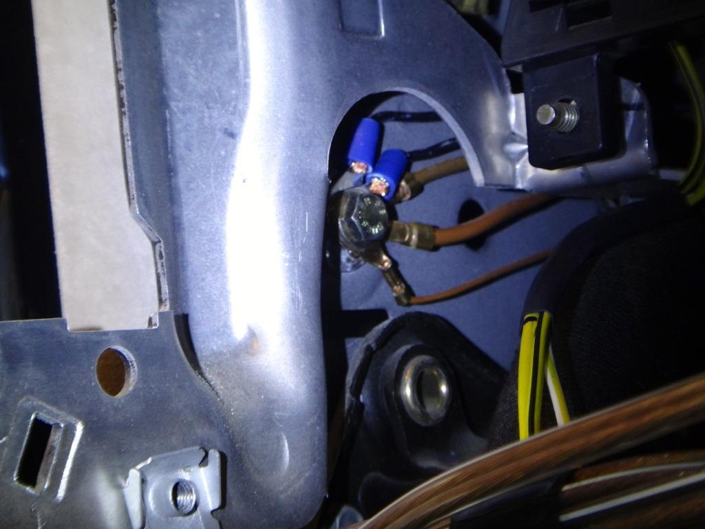
The last piece of the puzzle is getting a new power supply to the relays. I chose to install a fused power distro block which is secured to the knee bolster frame with zip ties. The block is connected to post 75x so the relays will only receive power if the key is in the on position.
Here is the block installed.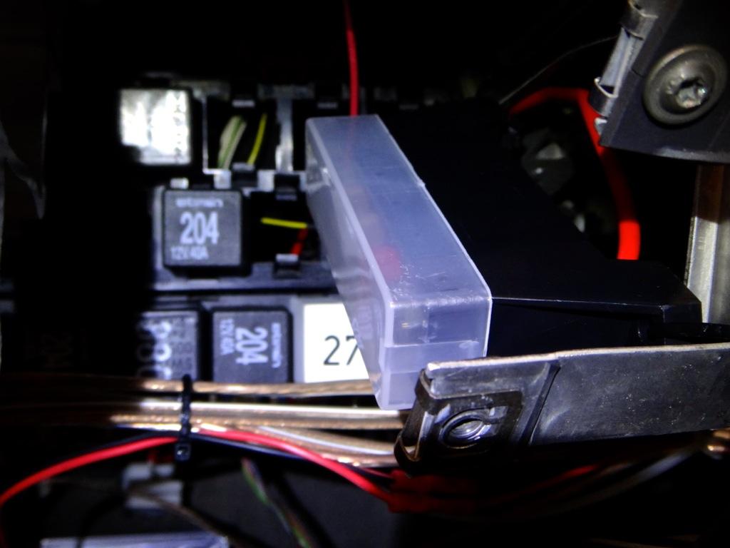
The relays are hooked up to 3rd and 4th slots. Both are running through 5amp fuses.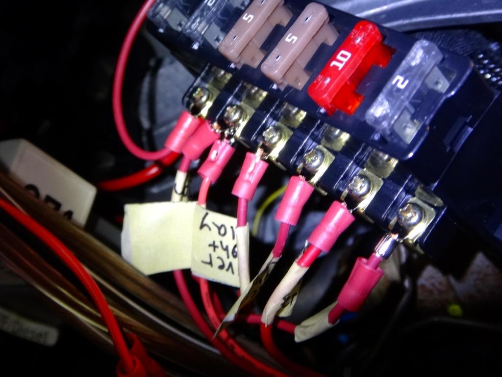
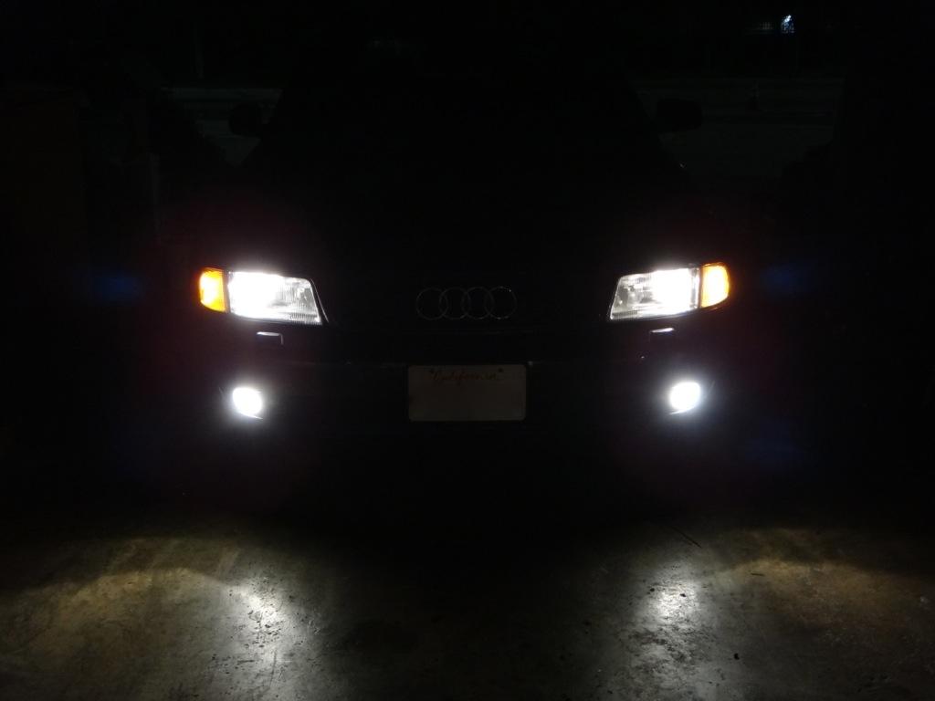
That's it! You headlights should now be running off the relays and you should never have to worry about melting your headlight switch again. If you are interested in having independent fog lights, this is a splendid time to tackle that project while you have everything apart. (http://www.audiforums.com/forum/b5-m...lights-198479/)