You must be logged in to rate content!
24 minute read

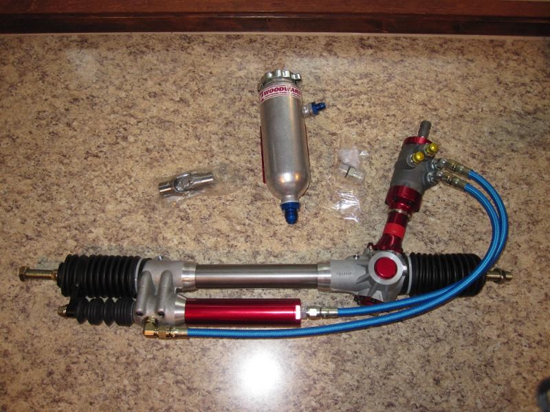
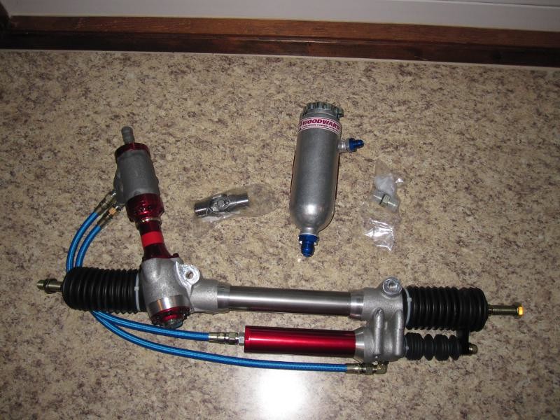
Woodward power steering project
Compliments of JMortensen @ http://forums.hybridz.org
12-17-2010
I haven't actually started on this yet, but I did talk to Tony Woodward and learned some interesting things, and I thought I'd put them down here for the benefit of everybody. So the plan for my car is to run the rear FA slicks all around. That's a 15x14 wheel with a 15x12 or 15x13 tire, both tires are designed for the 14" wheel, it's not a hellaflush stretch thing. I eyeballed it at 5" of scrub, which is A LOT, and I figured there was no way in hell I was going to do this without ps. I've been casually looking into the Subaru and other ps options for a while, and hearing things like the pump can't keep up, and the rack feels dead and steering feels numb, etc. I finally got interested enough to call Woodward steering, and got Tony Woodward on the phone. This guy is awesome, knows his stuff backwards and forwards, and really went through every one of my questions and answered them all.
So here is what I found out:
Do not buy an 18" race steering rack and put longer ends on it. Too much lever hanging out unsupported. He was pretty clear that this is a bad idea, was going off on people getting bad advice, etc.
Woodward racks come with a 6"Â stroke, Z comes with a 5"Â stroke. I just went and measured the Z rack at 1.8125 inches per turn of the wheel. The Woodwards come in a wide variety of ratios, but I was looking at a 3.14 in per turn rack, which would be VERY fast, about 1.75x as fast as stock. Now I'm thinking I might go slower, maybe a 2.5 or so inch per turn. Even that would probably be pretty twitchy for a street car, but should be great for autoxing, and since it doesn't require shorter steer knuckles, doesn't have an adverse effect on Ackerman. Some sort of steering stop will need to be devised. When I called Tony I had measured the rack travel wrong and thought I had 6 3/4" of rack movement because I measured at the wrong place, so I didn't ask about this, but the tech info on their website seems to indicate that what fixes this is using a housing that is 1" longer than the rack itself. Basically then the tie rod runs into the housing, preventing it from using the last bit of available rack gears.
Tony suggested a 950-1 servo and a 210 torsion bar and said that would give very light effort. He said if you put this rack on a new Mustang you could steer it with one finger. Effort can be adjusted later with a heavier torsion bar (spring that returns the wheel to center) or a smaller servo.
I gave him the center to center control arm pivot distance of 23.44"Â and he suggested that I use an off the shelf 23.25"Â wide rack measured from center of monoball to center of monoball. He said if the tie rod is shorter than the control arm, you'll get toe in on bump which is bad, and with the 23.25"Â rack it will be close enough to dial out bumpsteer to the point where the difference would not be noticeable. He said they could do a 23.44 rack if I wanted, but he would go with the shorter one just to be sure.
He suggested the high load option based on the scrub, and also said that 5"Â of scrub was nothing compared to what some modified stock cars run. This made me feel like I wasn't a complete idiot for considering running 5"Â of scrub. His opinion was that it wasn't going to affect the handling negatively, it would just make it nearly impossible to drive without ps. If you have ps, no problem.
He said Woodward is the only company that makes their own valves inside the rack, and that every other manufacturer was using smaller valves, and the restricted orifices cause the "damping" on a factory rack.. No damping on a Woodward rack, but you will have damping on any other rack, race or not.
Said the rack needs 2.6 gpm @ flow controlled rpm. Once you get up above a certain rpm, the rack still only puts out x gpm. He estimated most pumps put out about 3 gpm at their flow controlled rate, which was going to be achieved by about 1200 (pump) rpm. Also said that it would be likely that I would have a 5" pulley on the crank and a 6"Â pulley on the pump, so I would have .8x rpm on the pump vs at the crank. So basically, he didn't think pump volume was going to be a problem, even with a stock pump. Also said pump bearings are submerged in the ps fluid, so they can handle very high rpms with no trouble whatsoever
He suggested moving the rack back, and I told him that I already did that looking for Ackerman. He was impressed. The cost of the rack is $1560. As soon as I finish typing, I'll go back to rubbing some nickels together.
There is some really good tech info on Ackerman and a bunch of other stuff on their website, www.woodwardsteering.com
12-21-2010
I've dealt with Brian before, he is a good guy. Curious, how does the ps get the car speed? Sensor on the driveshaft? What was the cost? I guess another option would be a 1.5:1 steering quickener and the electric setup, but still have worries about feel and space might also be a concern. Not sure how much power you can get with the electric setup as well. If I'm adding a buttload of scrub and a quickener, will it keep up?
12-23-2010
I was talking to a guy who has a Woodward rack on a BMW, and I'm pretty convinced I'm going that way. Reason? I don't want to literally tear the stock rack apart. I'm going to be putting a lot of strain on the rack due to the crazy tire size and scrub. He was telling me that the Woodward rack is a lot beefier than any stock rack he's seen and that the loads that it can put up with are pretty tremendous.
4-25-2011
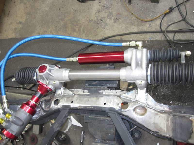
Ordered my rack today. Ended up with part number HLM266CC-2325/2475 950-1/210. So this is an HL rack with monoballs, high load, 23.25" rack with 24.75" housing 950-1/210. The housing being 1.5" longer than the rack limits the travel by 1.5", so it will have 4.5" of stroke vs the stock 5". I had previous issues with the tires hitting the TC rods, and although the new TC rods are in a slightly different location, I figured it wouldn't hurt to cut the travel back. I used my Ackerman charts and this brings my max angle on the outside wheel from about 33 degrees to about 30 degrees, so I don't think it will have a very dramatic effect on turning radius. Also ordered a KRC pump.
Will take pics when the rack is received.
5-9-2011
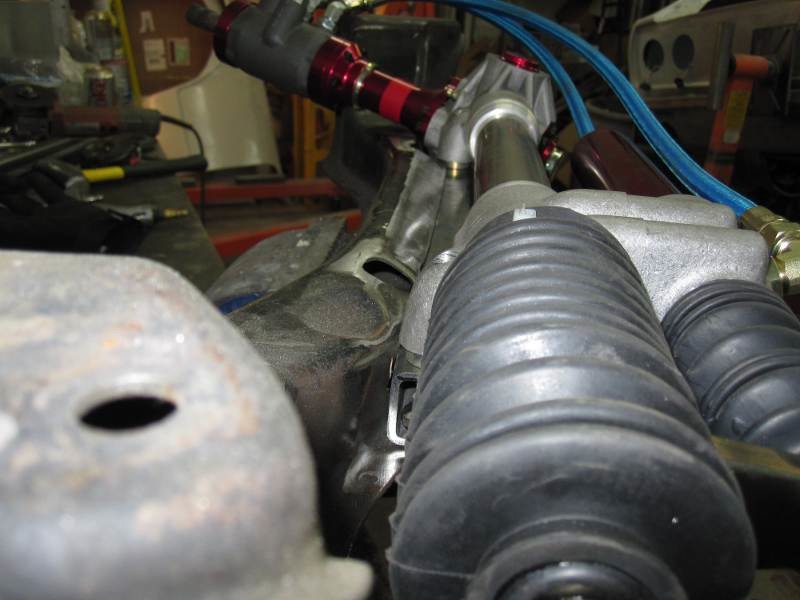
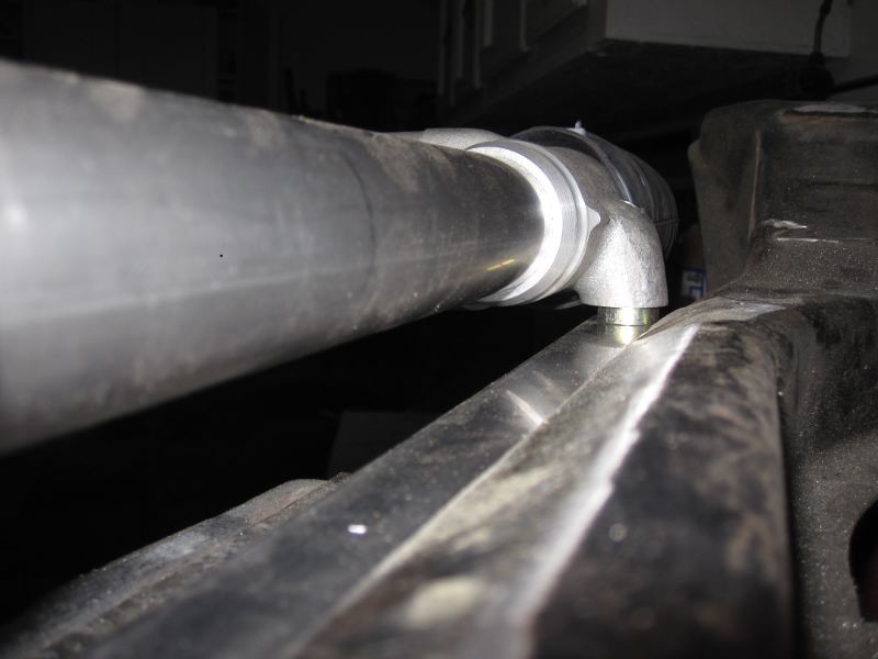
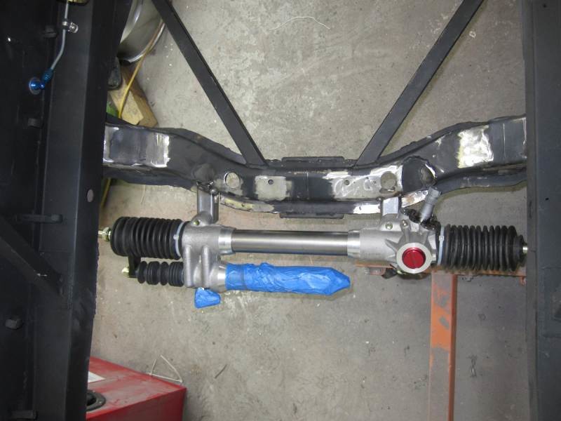
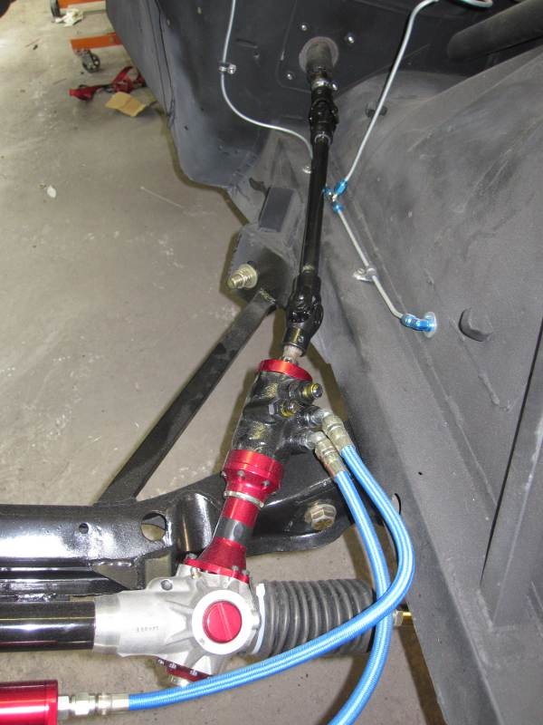
Got the rack today. Looks good. Now I just have to figure out how to install it. I thought this thing would have your typical circle track rack type of setup where the rack attached with three screws on each end. Looks like it attaches with one big ass bolt. I haven't measured, but I think it's 7/16", and there is a machined flat spot on the bottom of the rack where whatever mount is used will sit. I see this as good in that you can adjust bumpsteer out with shims fairly easily. It also appears that the pinion doesn't have much vertical angle to it, so that leads me to believe the rack will have to be mounted pretty high for the pinion to clear the crossmember. I could tilt the mounts, but then the hydraulic cylinder would be hanging down lower than the crossmember, which is already going to be pretty low. Don't want that. I guess the other option is to move the rack forward again, and that might unfortunately be the only solution. At least now after having looked at the Ackerman issue in detail I realize that I wouldn't be giving up much to move it forward a little bit.
I guess I'll just have to start playing with it and see what works, my biggest fear is that I can't get it in without redesigning the crossmember. Not that this would be a huge project in comparison to some of the others I've done, but it's just one more thing to do, and I need less of those.
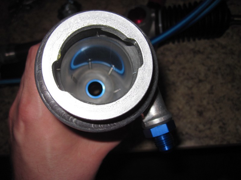
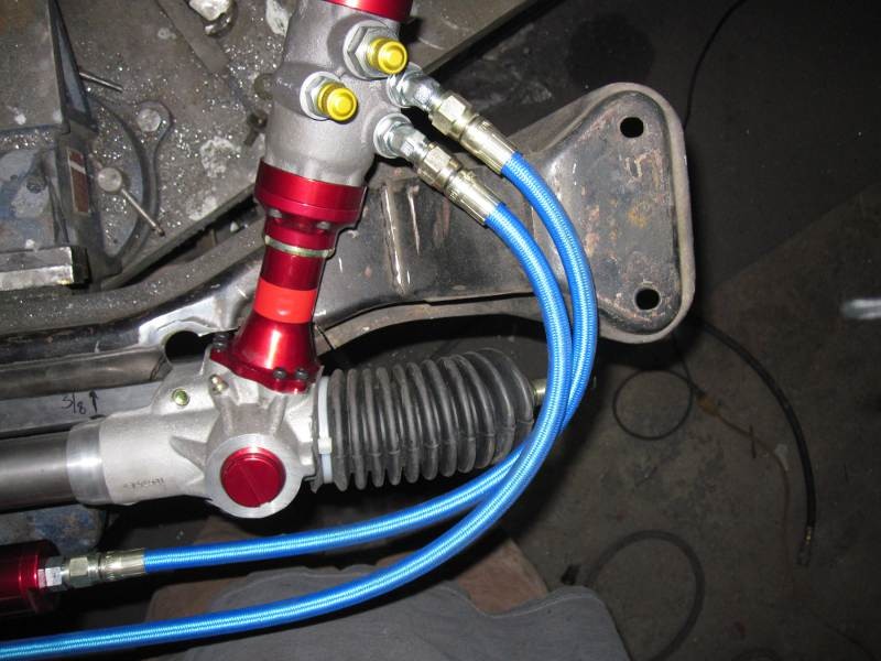
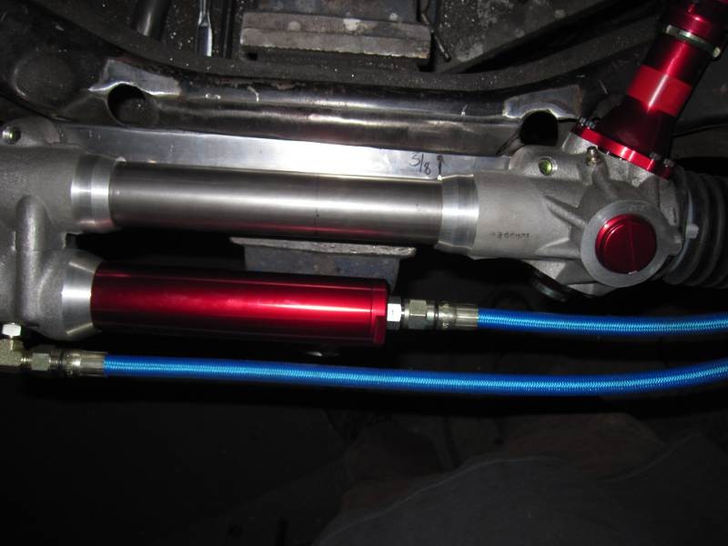
The reservoir for the ps fluid is a two layered can where the feed to the pump is at the bottom of the center can and the return dumps into the outer shell. There are perforated holes about 3/16" in diameter in the inner can to keep aeration to a minimum, and the can is nice and tall to keep any bubbles that make it through at the top. Came with a nice bracket as well.
Tony warned me that the rack would be so much more powerful that I should beef up the frame rails to deal with the additional strain. I had already done some strengthening of the frame rails, but the Z crossmember is not the strongest looking thing and I don't really see a good way to increase its rigidity.
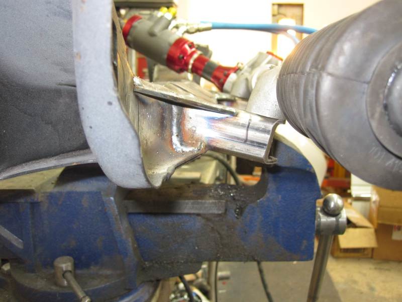
Just playing around with the rack and an old crossmember I figured out that the old 6 cylinder engine mount towers had to come off, so those got cut. No biggee as I need to fab mounts for the L33 V8 anyway. Then I realized that the horns that stick off the front that hold the stock rack had to get cut back just to get the rack in position, so I did that. At this point I was able to get the rack positioned essentially in the stock position, but about 1/4" higher. Moving the rack back to the stock position fore/aft negates the work I did to move the rack back, but after graphing it out on the Ackerman thread, the difference will be minimal, so I'm not worried about it.
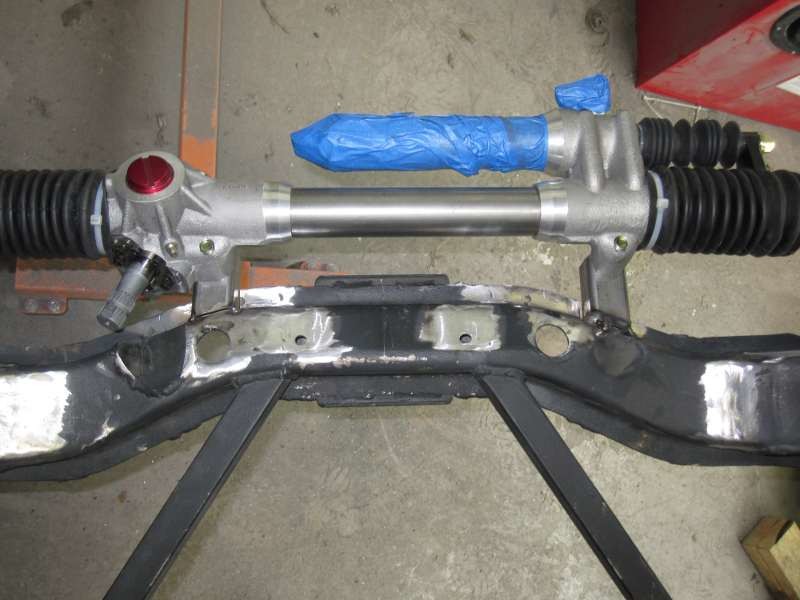
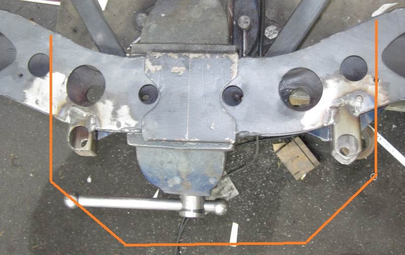
The rack mount is my biggest dilemma right now. I think the most logical way to mount the rack is to weld two pieces of angle iron to the front of the crossmember so that the flat part of the rack sits right on them. This may improve the rigidity a bit over the long unsupported saddles that the stock rack used, but they're not exactly what I would call "overbuilt". I thought of using a long piece of angle iron all the way across the front and I think that would be sturdier, but then there really wouldn't be a good way to put the bolts in, unless I drilled a big hole in the bottom of the crossmember, although that's sounding like it will be the best option at this point.
About the only thing I can think to do with regards to the crossmember would be to add a folded sheet metal gusset like a taco gusset between the crossmember and the frame rail, so that the lateral loads imparted into the frame go through two sides of the frame rail, instead of just the bottom. If anyone has any other ideas or previous experience, I'm all ears.
5-23-2011
Cary came up with a very good idea for rack mounting, which is basically 1.5" square tube with a 7/16" hole drilled in the top and a large hole in the bottom so the bolts can be inserted and a socket used to tighten them up. I checked it out on the crossmember and it looked like it was going to work pretty well, and the fab work actually looked pretty easy. Basically just cut the top of the crossmember so that the tubing rests on the bottom skid plate, and then weld it in across the top (presumably with a gusset. To follow Tony's recommendation, I'll double up the mount points so that they are 1/4" thick.
I've been slammed with the differential business, which is now really up and running (still nothing for Z cars aside from a couple seals, oil and LSD additive). I did have to order 1.5" square tubing and I got it in a couple days ago, but just haven't been able to make it out to the shop. I think with the way I'm planning on tying in the tube to the crossmember it will be OK, but I guess I'll have to put it together to test it out and see how it holds up. I'm finally getting back to normal on the work side of things, so I'm going to try and get out to the shop maybe tomorrow. I don't think the mount will be that hard to fab up, so I might be able to get it at least on the crossmember in the next couple days.
I did figure out that the rack mounting holes are not centered, so I probably didn't need to cut the engine mount towers off. Oops. I think I'll have to take a look and see whether I want to run the stock towers or make my own mounts from the motor to the frame rails, and that will determine whether I leave the crossmember that is in the car in it, or if I switch them out, which will be slightly more of a pain in the ass seeing as how I welded the crossmember in.
When I get it running and have run a few local races under me just to make sure that I'm comfortable that I've worked out the bugs, then I'm going to run every autox I can, so I'll probably be headed out your way, wheelman. I think it's going to be next season. I was doing really good over the winter, but this spring I haven't really done anything at all due to the new business coming together. Unless something changes, I think it's going to be on and off like this for a while.
5-25-2011
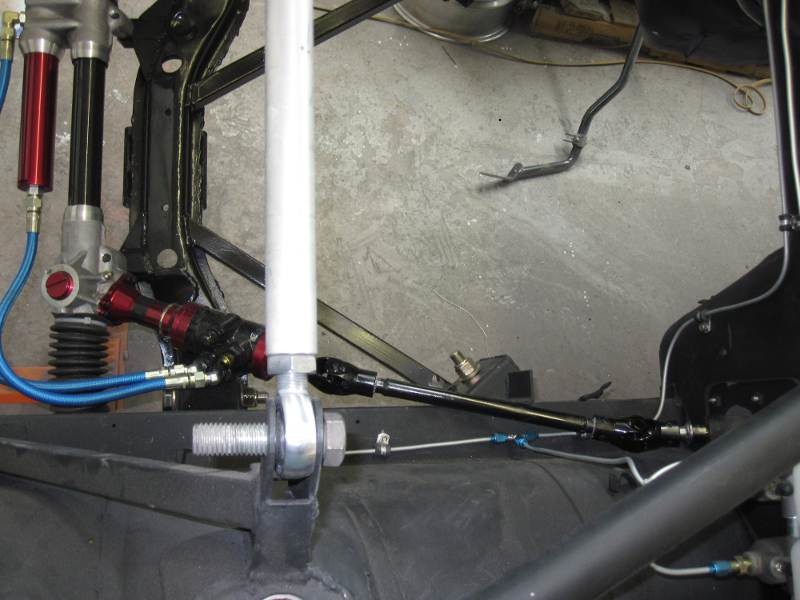
I made some progress and actually got the rack into the position the old rack was in after I moved it back, but now I'm at a point where I am a little worried about the position of the rack vs the crank pulley. I'm not using John's Cars mounts, but my main concern is whether I will be able to move the motor far enough back for the crank pulley to clear. I was planning on setting the motor back as far as possible, but I'm not sure how much room I have to work with. The top of the rack is exactly 1.5" taller than the crossmember with it sitting on 1/4" bumpsteer spacers. It will actually be 1/8" lower than that, so figure a total height from the crossmember to the top of the rack of 1 3/8". The stock crossmember has a raised section that is 2" wide from front to back. The rear part of my rack is 2 1/8" from the back of the raised portion of the rack.
In retrospect, the engine mount towers really did need to come off, so that wasn't wasted motion...
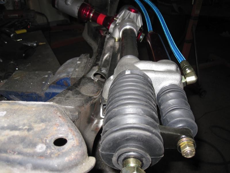
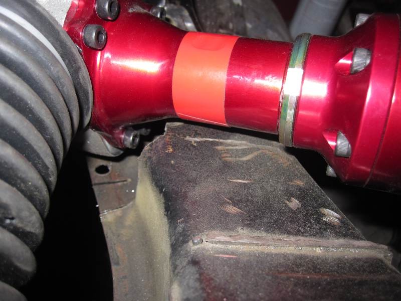
The C channel raised part of the crossmember has been cut and the plan is to weld the tube to it and the bottom of the crossmember. Sounds like it's going to be too far back though. I could start over with the other crossmember and move the rack forward again. A 1" change in the rack position forward really won't change steering angles much at all and would actually be 1/8" forward from stock. The problem is that the center tube on this rack is a lot thicker than the Datsun part, so I'll probably be RIGHT UP against the firewall if I do that. I guess the other option is cutting the firewall to clear the head. If you cut (or hammered) yours just enough to move the engine back 1" from where it currently sits, would you have to modify both sides, or just one? Can I get a pic of the firewall where the interference would likely be?
Thanks.
11-14-2012
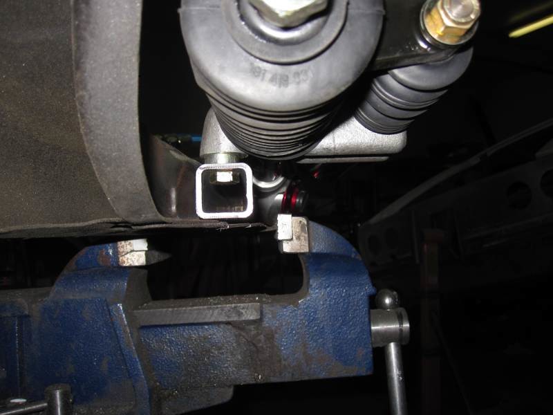
Back on this one. If there is one part of my build that has held me up more than anything, this is it. Stared at the mount that I had been planning on using for about a day and then cut it in half and decided to make two posts that stick out off of the front of the crossmember like the stock horns. The Woodward rack isn't symmetrical, so there was much hemming and hawing getting the thing centered on the crossmember. Finally just tacked a couple of 3/4" by 1/8" straps to the crossmember just to get the positioning correct. Once that was done I took a couple 1.25" square tubes and tacked them on to see what it looks like when it is all done.
Moved the rack forward to make more clearance for the crank pulley. After having an argument about Ackerman with Leon I charted out the Ackerman and found that at full lock moving the rack as far back as possible made about 1 degree of difference. Not worth the hassle. This position moves the rack to parallel with the steer knuckles, so gives parallel steer. I'll just run a buttload of toe out. After seeing how little difference it made, making room for the pulley was a bigger concern than maximizing the tiny amount of Ackerman I could get.
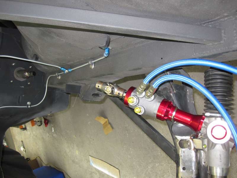
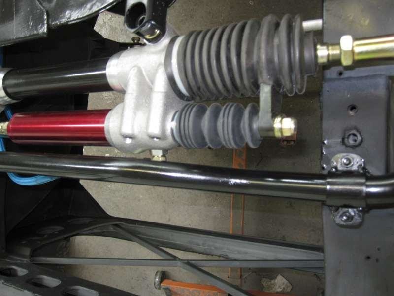
I didn't think I was going to be able to use the attached servo on the rack, but detaching it and getting the rack situated it looks like it will fit, just barely. Might have to notch the frame rail for clearance for the steering shaft. Other option is to run the servo remote and have 2 shafts. Trying to avoid that as it is yet more fabrication.
Looks like my pinion housing will be about 3/4" below the crossmember, and the front of the hyd cylinder will be at about the crossmember height. Question now is what to do about that. Thinking about building the crossmember lower and making a skid plate to protect the cylinder. I'd hate to ruin a rack because I drove over a curb at the track and smacked it on the ground, and this car will be low.
11-16-2012
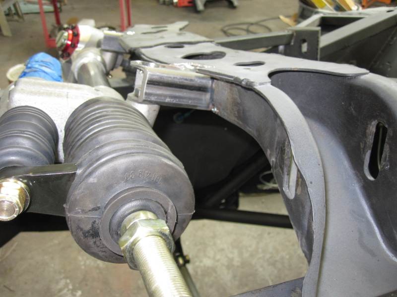
Got the rack mounting done, welded and gusseted and ready to rock. Still not sure about the skid plate idea. It looks like the aluminum housing that holds the hydraulic cylinder is also hanging down about 1/4", same as the rack mounting square tubing. That pinion housing is about 3/4" down. Still considering whether or not to do a skid plate.
I have a bunch of 1" square tube, so I could build a little frame and then weld a 1/8" plate to it and that would give clearance. Biggest problem is that the plate is heavy. I could just weld a section of square tube to the bottom of the crossmember on each side and then hope that the hyd cyl doesn't get whacked before the crossmember bottoms. Or I could have the square tubes sticking out off of the front like a spear. At least that way I could have them extend under the cylinder to give more protection without gaining all that weight...
11-17-2012
I called Woodward and talked to Tony, and that's what I ended up with. Cobramatt also has a Woodward rack in his crazy roadrace car. Not sure what process he went through to pick one, but I believe he has the same thing I do. Just looking at the catalog, it appears that the MR isn't made in a ratio as fast as I wanted, and I remember talking to Tony about the 13" wide front wheels and autoxing and he thought I needed the high load rack because of the stresses.
I'm not seeing a real clear description of how it mounts, but I think it's going to be similar. My real problem was that I was trying to move the rack as far back as possible which was going to cause issues with the crank pulley and I had my mounting tube in the wrong orientation. Once I figured that out it wasn't that bad, just one of those measure 47 times, weld once sorts of deals.
11-18-2012
Yeah, that's it. 5" of scrub and a lot of caster means a lot of lifting, and the quicker rack means you can load it one way and then the other faster, which I'm likely to do with an autox car.
11-29-2012
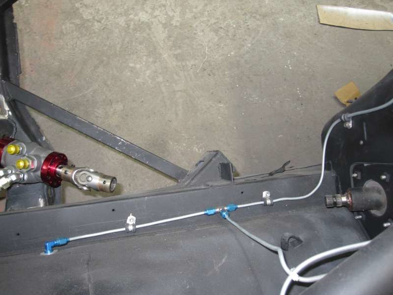
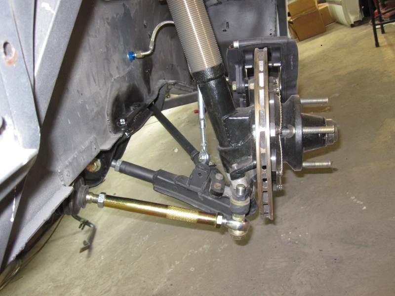
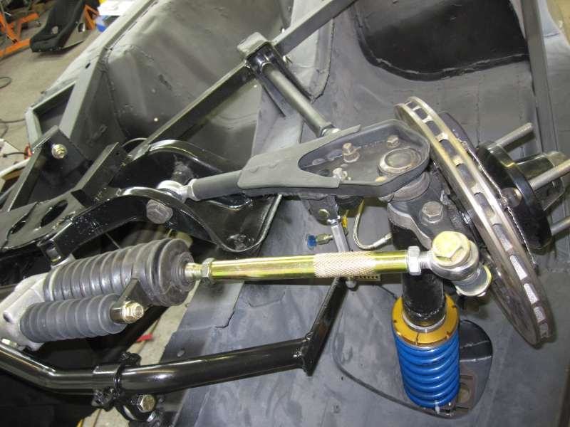
Got the linkage and everything done, so yay for that. Turns out the steering shaft fit without having to notch the frame rail. Steering linkage is all done. Still need to mount the ps pump and get hoses made for it, and do a quick release for the wheel, but the hard stuff is done.
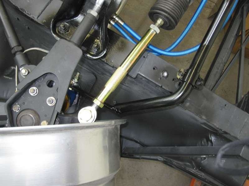
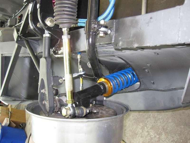
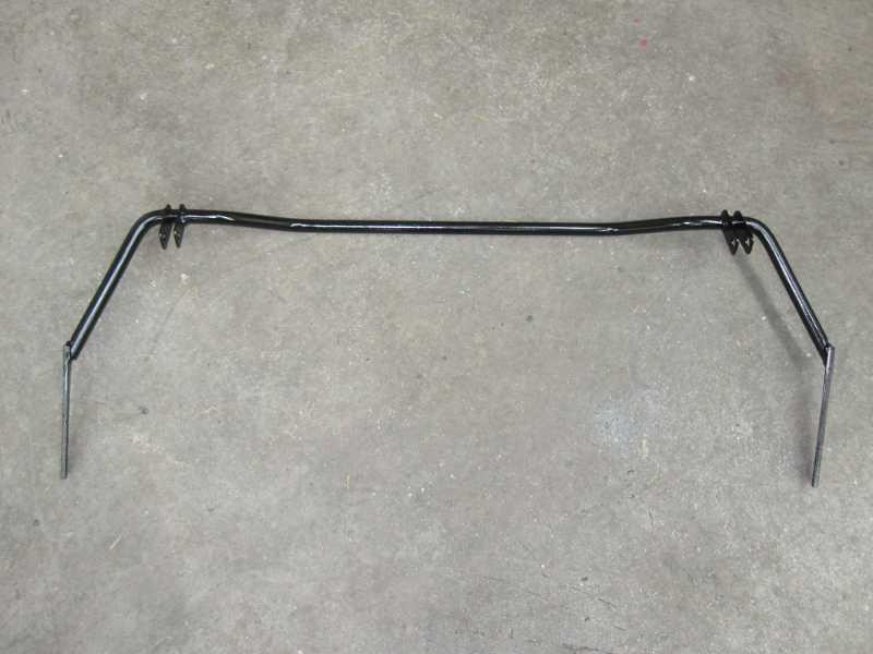
Then went to bolt up the sway bar. Boo. Turns out the hydraulic cylinder hits the bar when I turn right. Will have to relocate the sway bar mount forward and lengthen the arms which will make the bar weaker. Shouldn't be too hard. I have the sway attached to a rod end, so I made a new tube to weld through the frame with a nut on the end to thread the rod end into.
The end of the bar also hit my droop limiters, so will probably figure a way to limit droop with the sway bar as well. Got a bar from a 280Z that I bought earlier this year, so I'll have 2 bars to fit up and make work.
On the plus side, looks like this setup gives a lot of room for exhaust.
12-6-2012
Maybe you can come watch it autox next year. You might even get a ride if I get around to putting a passenger seat in it (planning on it but don't have a 2nd seat yet and have a lot more stuff to buy, so it's down the list a ways).
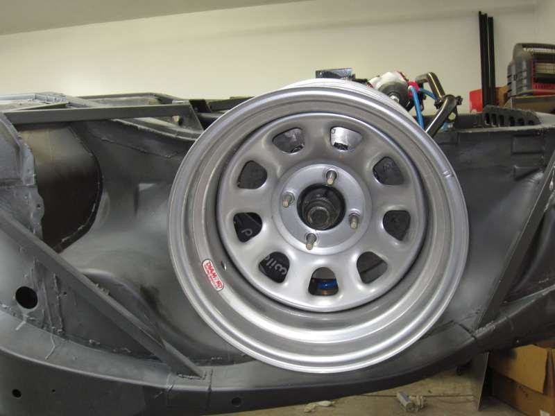
So here's the update on the sway bar(s). I got the stock 280 bar modded and had to cut the ends off of my old 1" bar to make it fit in the new location also. Serious PITA. Got it all in and checked for clearances. This diamond wheel is really the wrong offset. It's 3.75" offset and should be more like 4". Still there is about 5/8" of space between the wheel and the tire. I think that will be OK because the tires will be pretty narrow for the wheel width, 13" tread on a 14" wheel, so I don't think the sidewall will pooch out too far. If it does I may have to add rack limiters or wheel spacers. Hoping that it clears with no more hassle.
In getting the thing all together I realized that my brand new inner tie rod on the LH side is loose and has about 1/8" slop in it. That's not cool. Have to check with Woodward and see if they'll help me out or if I just need to buy another one.
The suspension is sitting on the bumpstops in the pics. You can see how little ground clearance there is going to be. I might actually have to run a longer external bumpstop to keep the splitter off the ground. We'll see.
Well, I learned something today! Inner tie rods are adjustable. Just back off the locknut, turn the main nut down until the slack is gone, and tighten up the locknut again. Good to go.