You must be logged in to rate content!
12 minute read
DRL Wiring For Pre-'13 Z's
Compliments of Dave N @ www.the370z.com
7-31-2013
First off, I want to give credit to TheW3r3w0lf and Fountainhead for information they provided in this thread: Daytime Running Lights + Switchback LEDs Their info was very instrumental with the development of these instructions.
This DIY will allow you to wire up a set of switchback LEDs for use as DTRL on pre-2013 Z's. The DTRLs will be active when the ignition switch is in the "ON" position but they will deactivate when the running lights or headlights are turned on (whether the headlights are set to auto or manually turned on). This set up can utilize the existing dual filament bulb or switchback LEDs (wiring differences will be detailed in the body of the DIY).
OBLIGATORY DISCLAIMER:You are doing this modification at your own risk and, as such, will take on any responsibilities for this installation successful or otherwise. Please read all the way though this DIY at least once to be sure you fully understand the steps before starting this project
The modification does not require significant electrical skills (no soldering required), however basic mechanical skills are needed to do this DIY.
Items required:
Tools:
Wire stripper/crimper
Small flat blade screwdriver
10mm socket/wrench
Heat gun (required if using heat shrink tubing)
Jack and jack stands
21mm socket for tire removal (preferably 1/2" drive, or use the tire wrench in the spare tire tool kit)
Materials:
Automotive grade relay (typically 12V/40 Amp rating) - must be "Normally Closed" (you can find these at electronics supply stores and some automotive supply stores - they may be combo Normally Open/Normally Closed relays).
Here is an example available through Autozone
Here is an example available through Radio Shack *Since specifications change, and photos of the products used on websites aren't always accurate, be sure to verify with the seller that the relay will support a "normally closed" circuit before you purchase it.
5 Pin socket w/leads for the relay - must match the pin pattern on the relay. Here is an example available through Radio Shack
16 or 18 gauge wire in colors of your choice (2 colors were used in my installation: blue for connecting the power leads to the lights/relay and black for ground connections
Ring connectors Here is an example available through Autozone
Butt splices
Inline splices
Heat shrink tubing (or electrical tape).
Step one:
Disconnect the battery positive (+) terminal
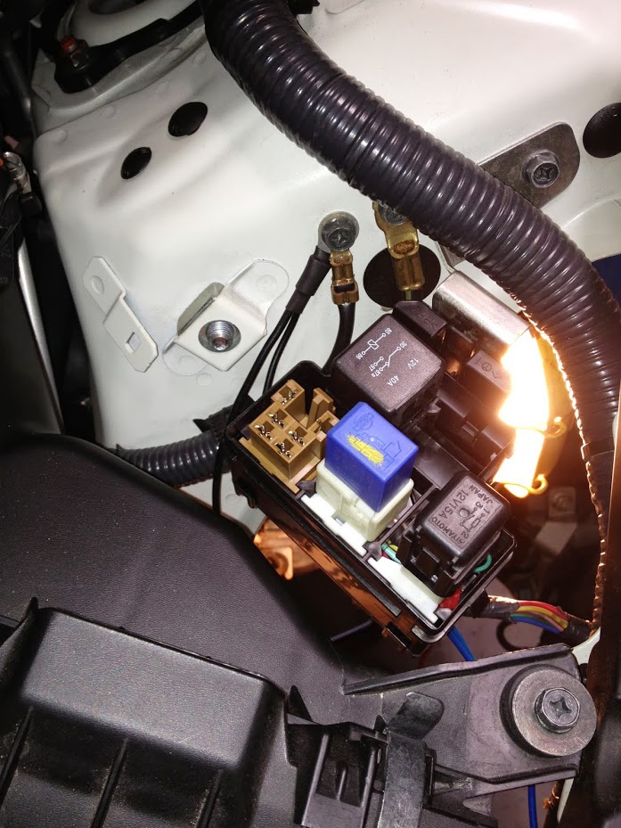
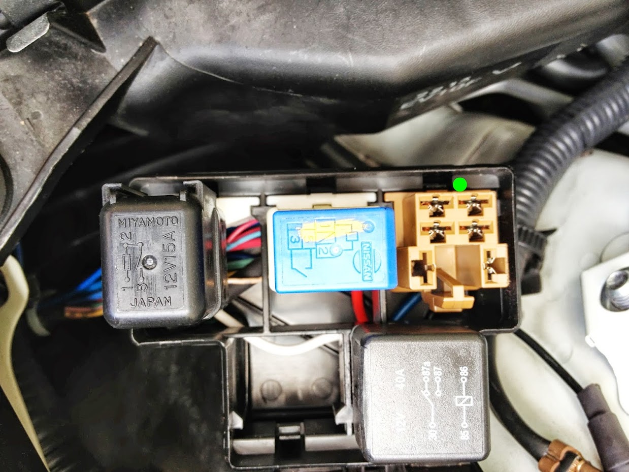
Next, locate the relay box on the driver's side - just forward of the strut tower:
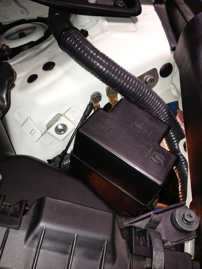
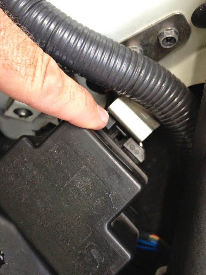
Depress the lock tab that secures it to the bracket and slide it upwards until it is out of the bracket.
Turn the relay box upside down and remove the bottom cover by releasing the snap-tabs (yellow dots).
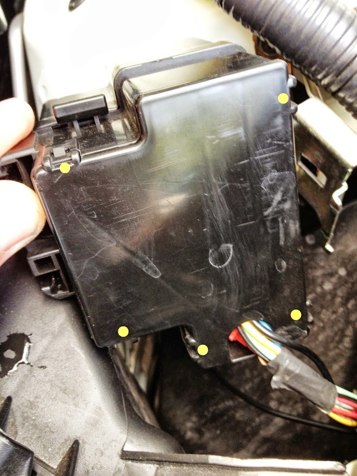
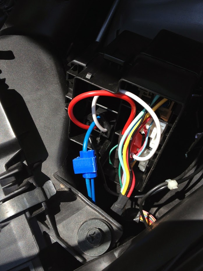
Remove the cover and locate the DTRL RELAY using the diagram on the cover.
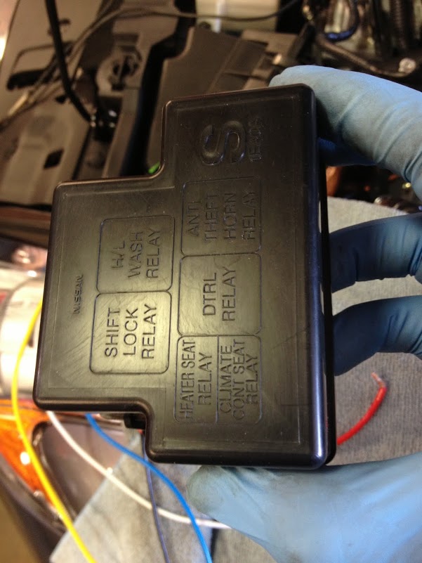
The DTRL relay is the blue relay mounted to the white connector base (note: this photo shows the new relay (black) already installed).
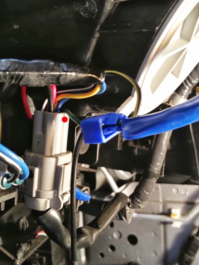
Using a small flat blade screwdriver, depress the lock tab (left of red dot) to remove the relay and its connector from the black enclosure (it will slide up towards you).
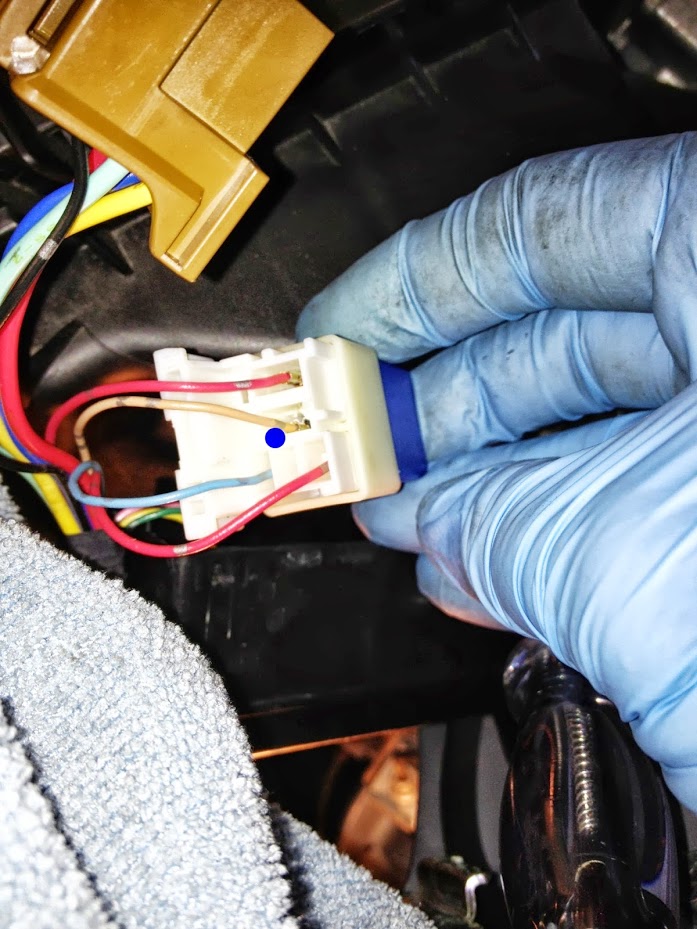
With the DTRL relay free from its mount, turn it over and locate the light brown (see blue dot in photo below).
Referring to the attached wiring schematic (courtesy of Fountainhead)
Look at the relay you purchased and note the connection diagram on the top of the relay (note: look for this info when buying the relay - it should either be printed/embossed on the relay or printed on the packaging).
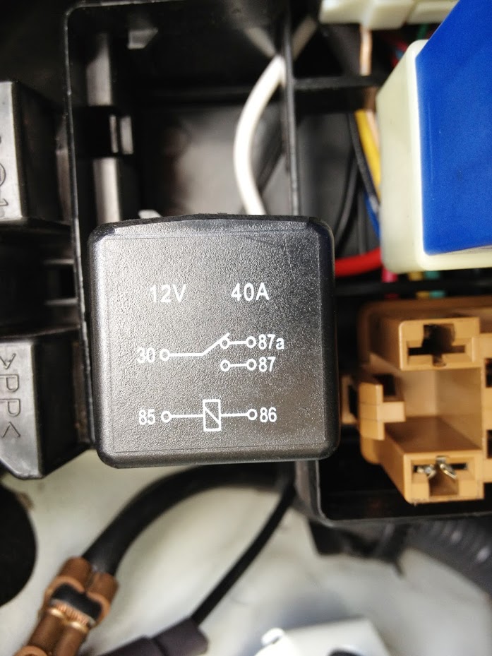
For the relay I used, I noted the pin numbers on Fountainhead's wiring diagram as shown below:
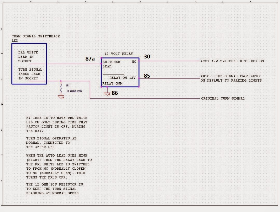
Please note that the relay you have may show different pin numbers. The important thing to do is to associate the pin numbers (if different) with the same positions on the relay diagram in the picture.
When making the following connections, you can clean up the installation by cutting the wires to be just long enough to reach the adjacent connectors. This will make it much easier to tuck these wires into place when reinstalling the bottom cover for the relay box.
Splice the wire for relay pin 85 (the relay connector should have numbers embossed in the housing to identify which wire connects to the relay) to the light brown wire on the DTRL relay by using an in-line splice (sample image of in-line splice shown below).
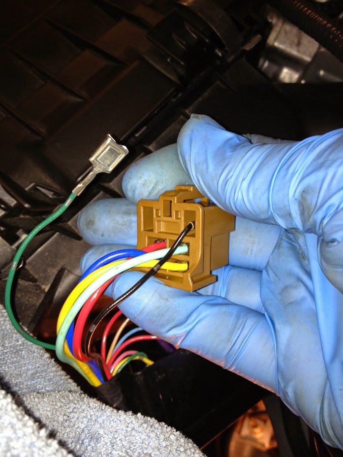
After the splice is made, you can replace the DTRL relay into the relay housing base and remove the brown relay connector (green dot):
Remove the green wire (I chose to remove the terminal from the connector, but you can simply cut the wire as close to the base as possible if preferred).
Cut off the terminal from the wire and strip approximately 1/4" of insulation from the end. If using heat shrink tubing to seal the splice, cut approximately 1-1/4" ~ 1-1/2" of heat shrink tubing and slide it onto one of the wires BEFORE making the splice. Using a butt-splice, connect the green wire to the wire for pin 30* of the relay. After crimping the butt-splice, slide the heat shrink tubing over the splice and use a heat gun to shrink the tubing. Be careful not to use too high of a heat setting otherwise you may melt the tubing or wire insulation. If electrical tape is being used, it can be applied after crimping the butt-splice.
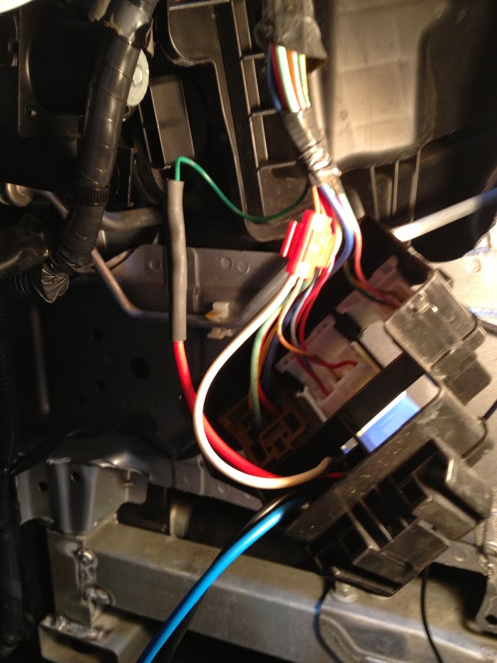
Crimp a ring connector to the wire for pin 86. For my installation, I combined this wire with the ground connection for the driver side load resistor:
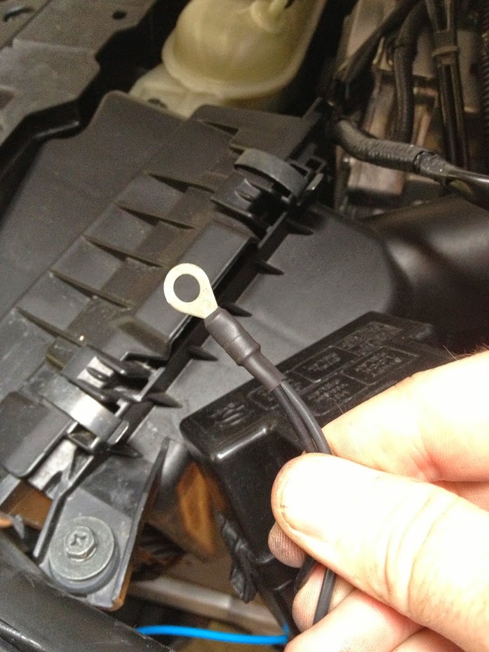
...and connected them to the chassis ground adjacent to the relay box:
Do not install the bottom cover yet. This will be done at the end after you recheck all the connections and test the system.
Step two:
Carefully jack up the front end and place it on jack stands
Remove both front tires
Remove the plastic clips securing fender liners on the driver and passenger sides.
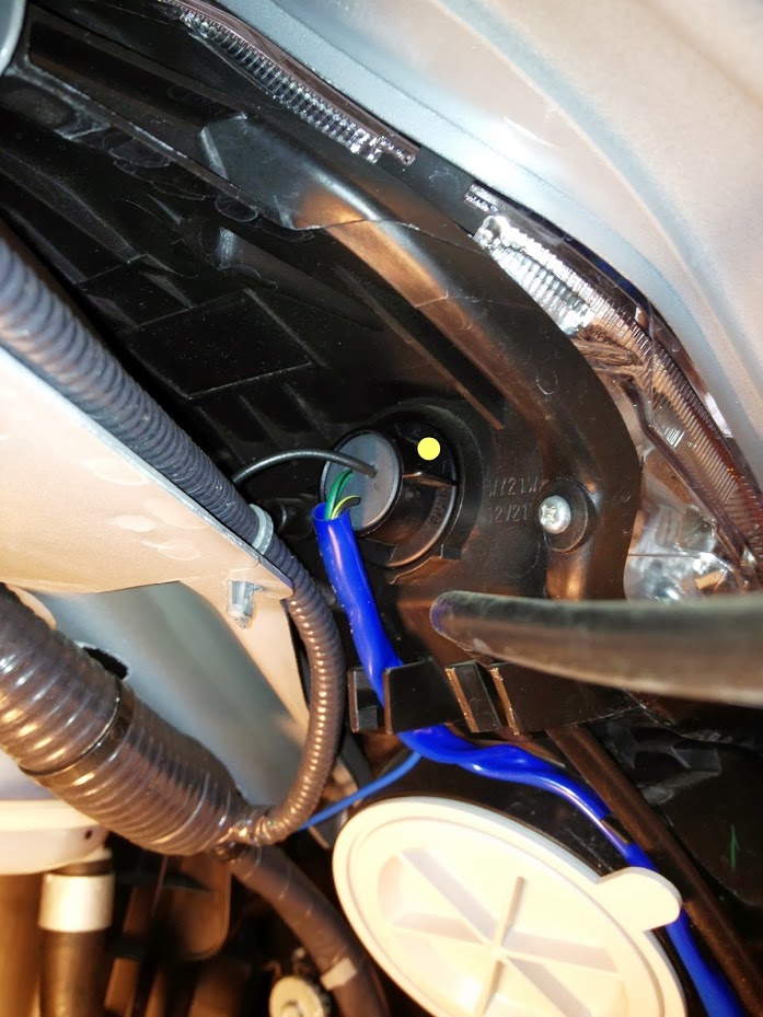
Locate the parking light socket and twist the socket to the left to remove from the headlight housing (yellow dot; passenger side shown in the photo below - left side is similar):
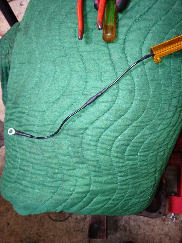
Take the black wire and pull it out of the blue sleeve. Cut off the black shrink tube that is sealing the end of the wire and strip approximately 1/4" of insulation off the end of this wire. Take a butt-splice and a piece of heat-shrink tubing, slide the heat-shrink tubing onto the black wire, and then crimp the butt-splice to it. Next, run a length of wire (avoiding sharp metal edges or moving parts) from the relay box to the headlight area and crimp this wire into the other end of the butt-splice. Slide the heat-shrink tubing in place and shrink it (or wrap with electrical tape). At the relay box, connect this wire to pin 87a of the relay connector using a butt-splice and heat-shrink tubing. When doing this for the passenger side, you will need to run the wire over to the relay box on the driver side fender well and connect it to the wire for pin 87a using a butt-splice. Be careful when routing this wire to avoid contact with moving parts or sharp edges. For my installation, I routed the wire along the front of the radiator area by removing the black plastic cover on the front core support.
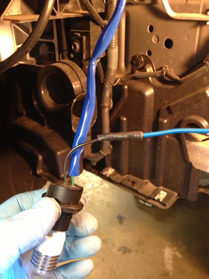
Here is a picture of the in-line splice connecting the passenger side wire to the relay connector.
**
FOR SWITCHBACK LEDs, PERFORM THE NEXT STEP TO INSTALL THE LOAD RESISTOR. IF USING THE OEM DUAL-FILAMENT BULBS, SKIP THE LOAD RESISTOR INSTALLATION.
**
Two load resistors should be supplied with the switchback LEDs. One will be needed for each LED installation.
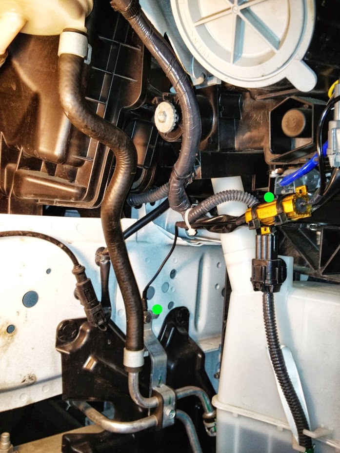
Locate the grey connector attached to the headlight housing and find the wire that is green with a black stripe on it. Attach an in-line splice to connect one lead on the load resistor with the green/black stripe wire (the blue sleeve may need to be trimmed back a little).
On the other resistor lead, attach a length of wire suitable to reach a grounding point on the car. Use a butt-splice and heat-shrink tubing (or electrical tape) for this connection. Install a ring connector on the opposite end of the wire.
Attach the ring connector to chassis ground and secure the resistor to prevent it from rattling or bouncing around (green dot; passenger side example shown in photo below):
Repeat the above steps for the opposite side.
Step Three:
Recheck all electrical connections to be sure they are securely crimped and per the relay wiring diagram. Make any corrections if needed. Once everything is checked, reconnect the positive terminal on the battery. Turn the ignition switch to "ON" and check that both LEDs illuminate in white:
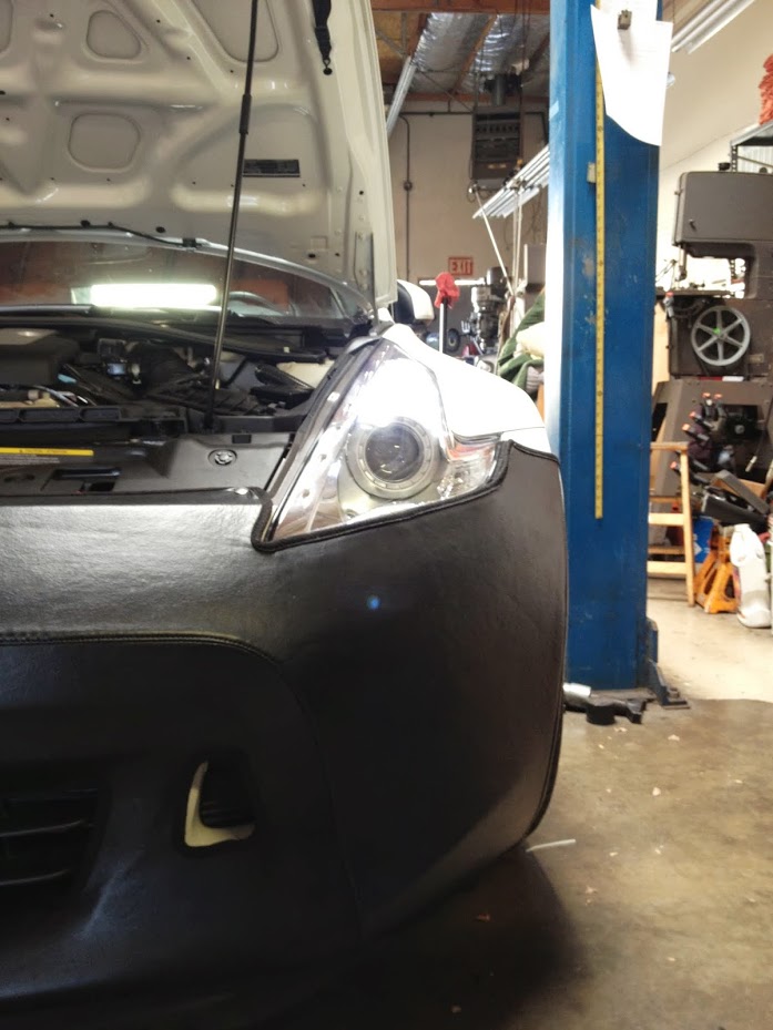
Next, check each turn signal operates correctly and illuminates in amber (this photo is a little washed out from the overhead lights):
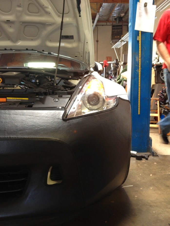
If the turn signal flashes quickly (hyperflash), recheck the connections to the load resistor to be sure there are no bad crimps or bad ground connections. Note: if checking the turn signals using the hazard switch, you may not find the hyperflash problem - you must check the turn signals individually.
Finally, turn the parking or headlights on and confirm the DRLs turn off.
Turn the ignition switch off and pat yourself on the back for a job well done.
Now that everything checks out OK, make sure all wire installations are secured and routed away from anything that could damage them.
Reinstall the following items:
Fender liners
Wheels
Bottom and top covers for the relay box
Relay box on the inner fender
Anything else that was removed for the installation
Don't hesitate to PM me if anything isn't clear from these instructions.
This completes the DIY. Enjoy!
**No fuses were harmed during the creation of this DIY** ;-)
8-5-2013
There are one or two references in the DRL post I linked at the beginning of the DIY. To avoid a lengthy search and click exercise, here is the info I gleaned from that post:
One person posted this link: 7441 Dual Color No Error High Power Projector LED Turn Lights Resistors 7W 68C | eBay, however I had two failures out of four bulbs that came from Kaizenmotor on eBay (and so far I have not been able to locate their contact info for a refund). Here is my post describing the problem with the Kaizenmotor LEDs. I'd stay away from these for now.
Here is the link to TheW3r3W0lf's post on sourcing LEDS: Daytime Running Lights + Switchback LED’s
I have not researched these bulbs yet so I can't say if these are any better than the first ones I tried.
Good luck, I hope this helps.