You must be logged in to rate content!
20 minute read
Disassemble the OEM Shortblock
Compliments of STI Sibb @ www.iwsti.com
6-2-2009
***This will take a while so don't attempt anything listed below. It is subject to a lot of change.***
Scope:
The following process is based on the 07 WRX / STI Service Manual and is intended to help you disassemble your OEM shortblock.
Service Manual Reference:
2007 > Impreza (WRX & STI) > Service Manual > Engine Section (H4DOTC) (Part1) > Mechanical (H4DOTC) > Cylinder Block
http://techinfo.subaru.com/html/ixSe...%29&pid=267755
Disclaimer:
When in doubt, have a qualified technician or shop repair your engine for you. The following procedure contains guidelines for disassembling the 2007 STI OEM shortblock and may not accurately reflect your particular car's engine. Read your Service Manual first when disassembling the OEM shortblock.
Safety:
Wear mechanics gloves, longsleeves, and safety glasses when disassembling the OEM shortblock. Gloves and longsleeves protect against abrasions and cuts from sharp metal. The shortblock has several razor sharp edges where the aluminum has been machined. The shortblock may contain coolant, oil, and liquid gasket. The shortblock weighs ~135 lbs when packaged for shipping. Make sure it sits on a workbench that can support this weight in addition to any forces you place on it.
Tools:
3/8" Drive Ratchet
1/2" Drive Breaker Bar
1/2" to 3/8" Drive Adapater
3/8" Drive Swivel Adapter
Socket Extension
10mm 6 Point Socket (short)
12mm 6 Point Socket (short)
12mm 12 Point Socket
22mm or 7/8" Socket
#3 Phillips Head Socket
4mm Hex Bit Socket - http://www.harborfreight.com/cpi/cta...emnumber=98229
14mm Hex Bit Socket - http://www.harborfreight.com/cpi/cta...emnumber=98229
Nylon Pry Bars - http://www.harborfreight.com/cpi/cta...emnumber=67021
Telescoping Magnet
Utility Knife
Needle Nose Pliers
OEM Jack
Flashlight
Hammer
Adjustable Wrench
Shop Rags
Long & Thin Flat Head Screw Driver (at least 8" long)
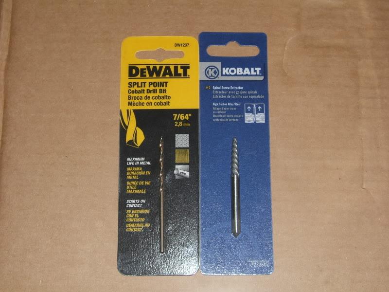
Power Drill
7/64" Drill Bit
#2 Easy Out
Crank Pulley Bolt - Subaru Part #12369AA011
Special Tools:
The following tools can be purchased from Subaru to ease the process of disassembly. These tools can not be purchased directly from the dealership, but several aftermarket parts companies are willing to supply them. They are expensive. As such, I have not used any of these in this DIY. Some of the helpful links at the bottom of this post demonstrate fabricated tools.
499097700 - Piston Pin Remover
Materials:
Electrical Tape
Packing Wrap
Cardboard
Ziploc Bags
Sharpie Pen
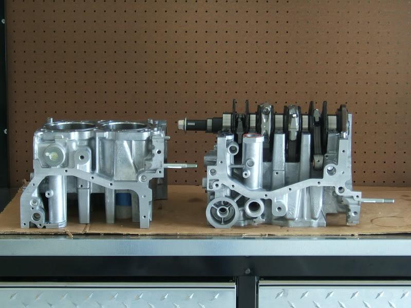
Overview:
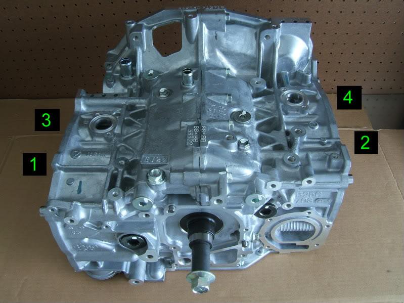
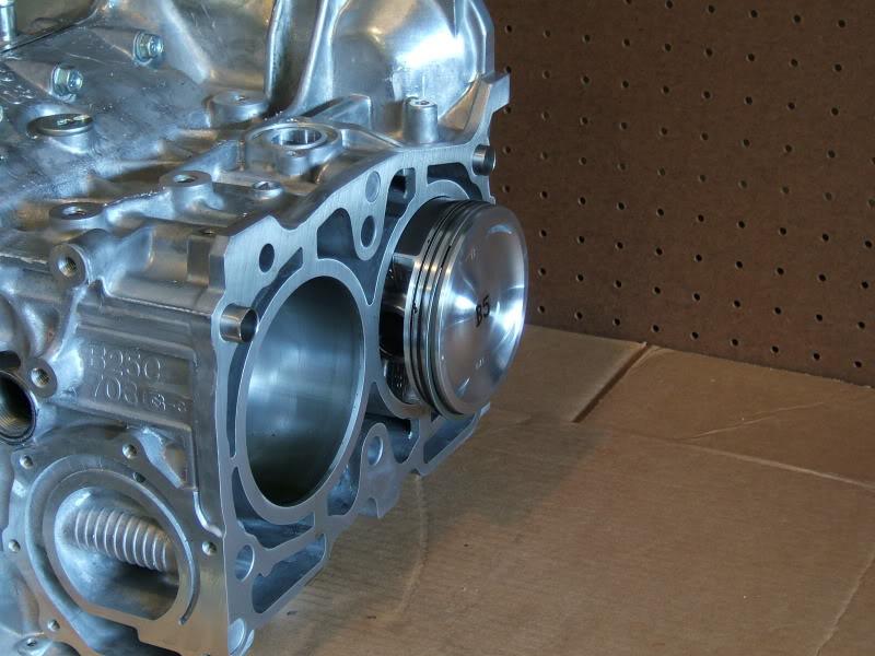
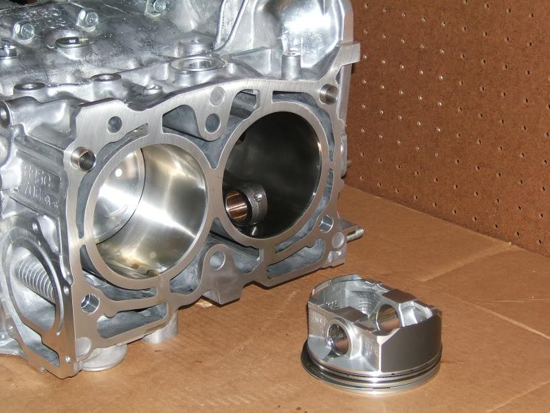
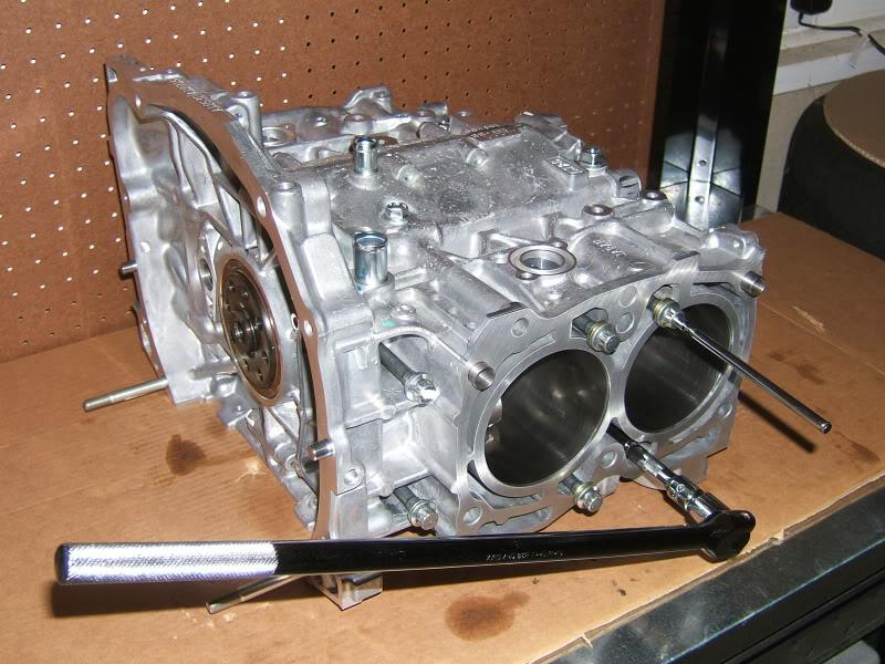
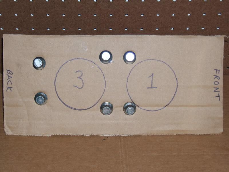
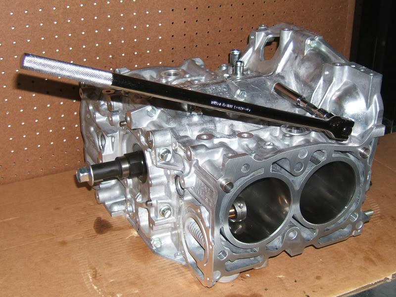
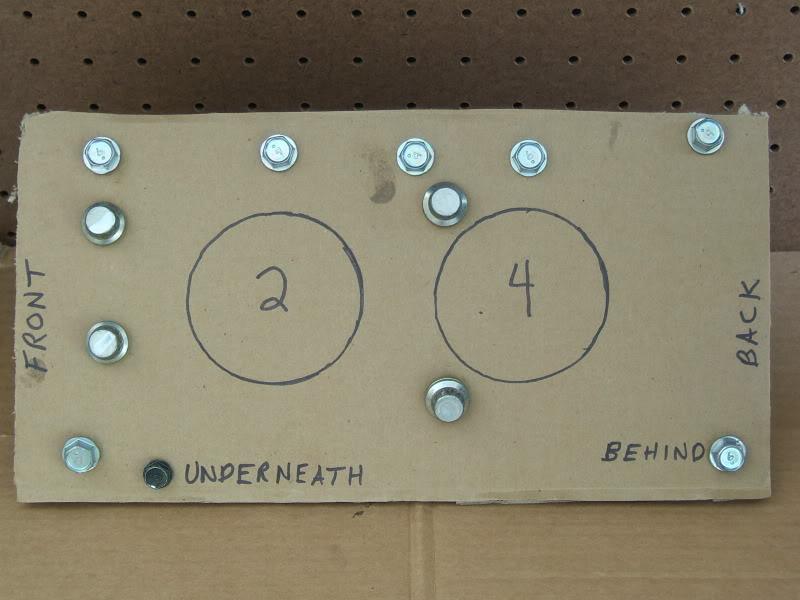
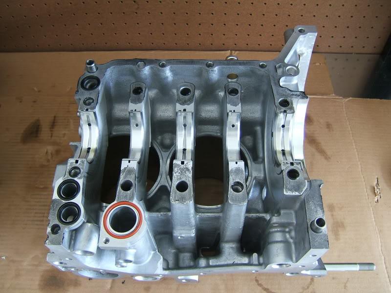
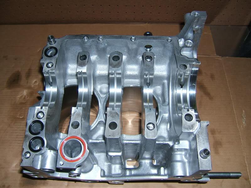
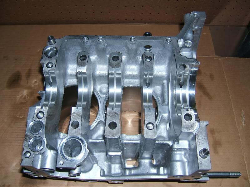
The OEM shortblock is composed of two aluminum cast sections that are held together with bolts and liquid gasket. A forged crankshaft is sandwiched between bearings in the center and is connected to the rods, piston pins, and pistons. The OEM shortblock comes with cast pistons and rods. There are passages built into the block for the movement of oil and coolant. Gaskets, O-rings, and liquid gasket are used to keep theses fluids inside the motor during operation. The 4 cylinder positions are shown in the photo below. Refer to these positions for all instructions.
Procurement:
It is not necessary to buy a new OEM or built shortblock depending on the condition of the one you take out of the vehicle. Many times the block can be reworked by an engine builder and sized for new pistons and bearings. If the block is in bad condition, an OEM or built shortblock can be purchased from several vendors listed on IWSTI. It's important to search for a block based on the price, reviews, and vendor reputation. An OEM shortblock will cost at least $2,000 from most vendors. Aftermarket vendors will typically beat the price of any dealerships. If you browse through the aftermarket websites, they can give you an idea of the products they offer, but it is better to call them to find out exactly what they have. The vendor should ask for identification of the vehicle which may include the year, make, model, VIN, and Engine Code. These items can be found on a nameplate under the hood. Keep in mind that replacing a shortblock may involve work to the heads such as resurfacing. It will involve replacing the head gaskets and possibly other seals. It may also involve replacement of the water pump, oil pump, oil cooler, pulleys, and timing belt. The cost of replacing the shortblock can go up quickly so be prepared prior to starting. I'd like to give a quick thanks to P&L Motorsports for processing my shortblock order.
Preparation:
Read the Service Manual instructions for disassembling the OEM shortblock. Read or watch DIY's to help fill in the gaps or find alternate means to accomplish the same task. Prior to starting, acquire a sturdy workbench and some shelving to store parts. Prior to working on the shortblock, put down 2 or 3 large pieces of cardboard on the workbench top to help protect the machined surfaces from damage. Damaged surfaces do not seal well and may require repair.
Helpful Links:
Some of these are directly related while others deal with STI engines in general.
Nasioc - STI Engine Compendium - http://forums.nasioc.com/forums/show....php?t=1431376
Nasioc - STI Shortblock Disassembly - http://forums.nasioc.com/forums/show....php?t=1435733
Youtube - STI Shortblock Piston Removal - http://www.youtube.com/watch?v=xmlNI...eature=related
Youtube - STI Shortblock Rebuild - http://www.youtube.com/watch?v=byfNt-0iP6U
Youtube - STI Shortblock Honing - http://www.youtube.com/watch?v=f6CEkkG-j8s&feature=fvw
Youtube - STI Shortblock Sleeving - http://www.youtube.com/watch?v=SIgq2...eature=channel
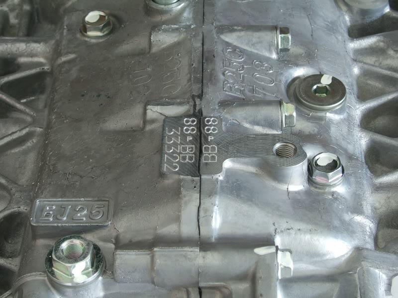
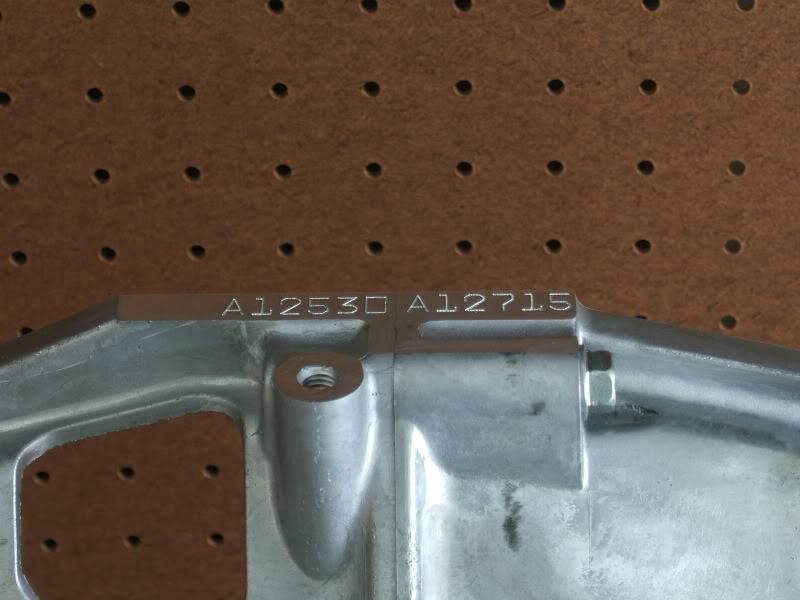
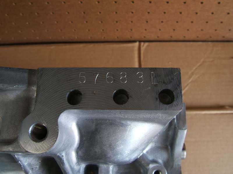
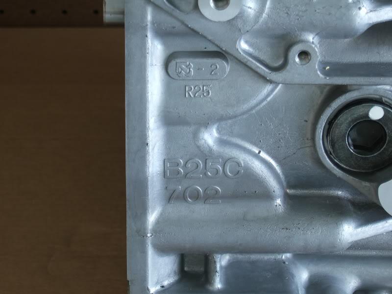
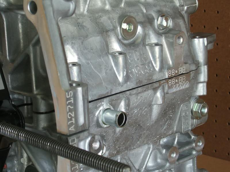
OEM Shortblock Markings:
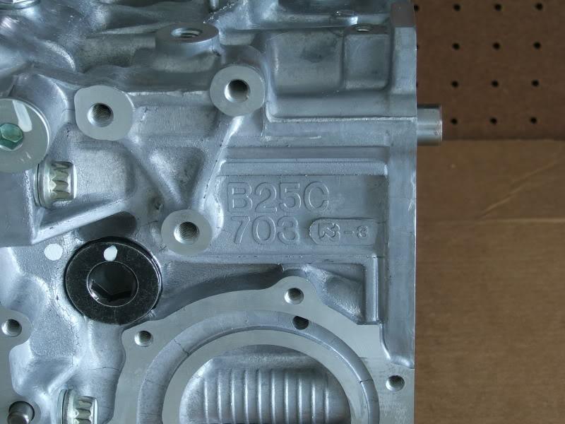
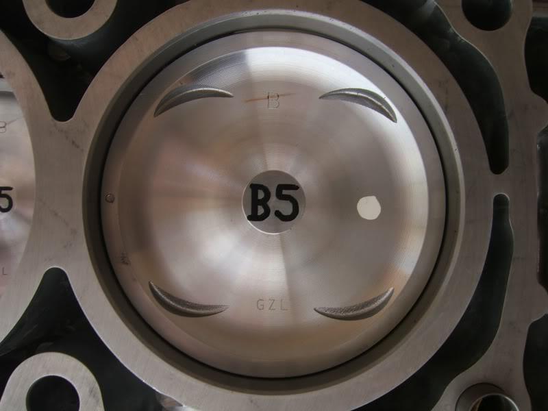
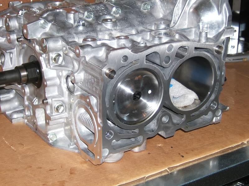
1. The "BBBB" in pic #1 of your 2nd post refers to the cylinder bore sizes and which size piston they used (one letter for each cylinder). There's A and B bores from my understanding (most blocks are a mix of A's and B's). That's the only marking I know pictured. -Deuce Cam
2.
3.
4.
5.
6.
7.
Removing the Pistons:
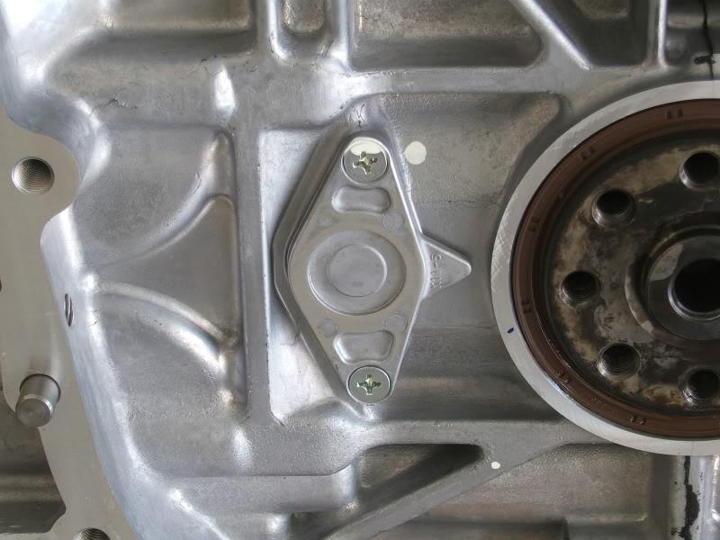
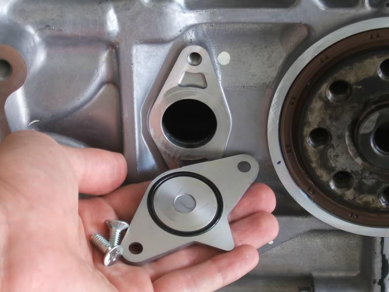
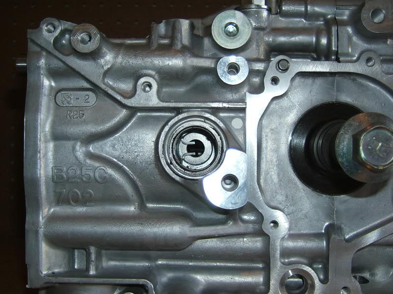
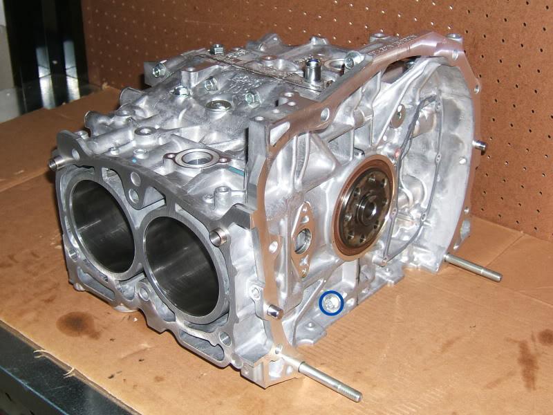
1. Remove the rear service hole cover. It is held on by 2 screws which require a #3 Phillips head socket (or screwdriver) to remove. When removing these screws, press in on the ratchet to prevent the bit from slipping out of the screw's head. If you end up stripping the head, use a drill bit and an easy out as described in step 2 to remove the screws. Note that the rear service hole cover uses an O-ring to create a seal against the shortblock housing (Picture 2).
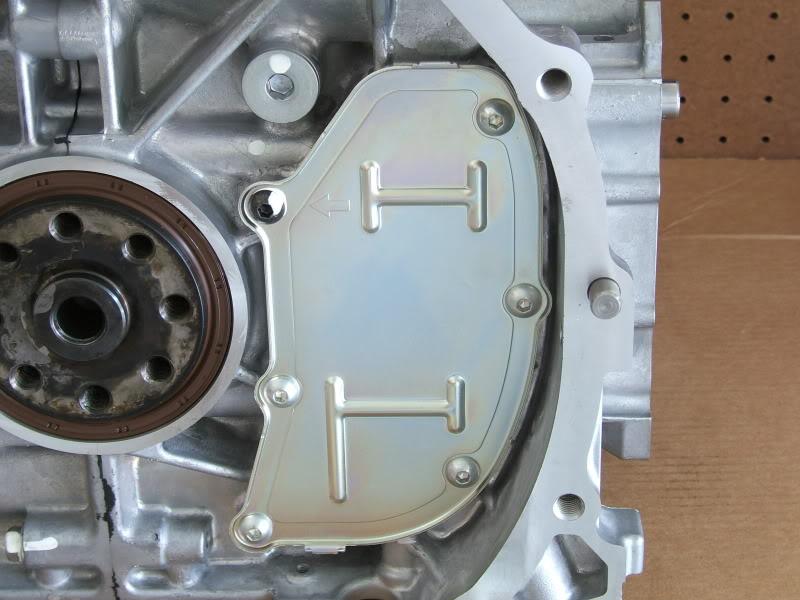
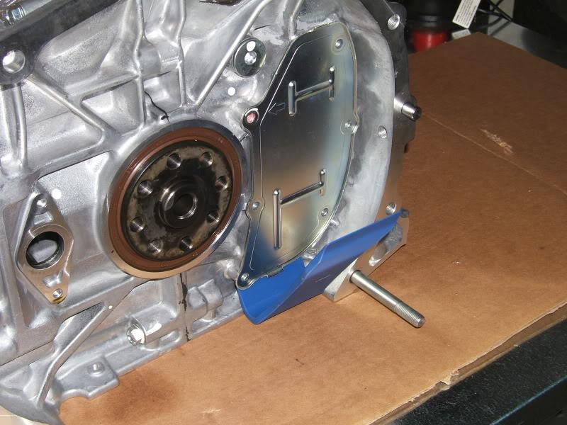
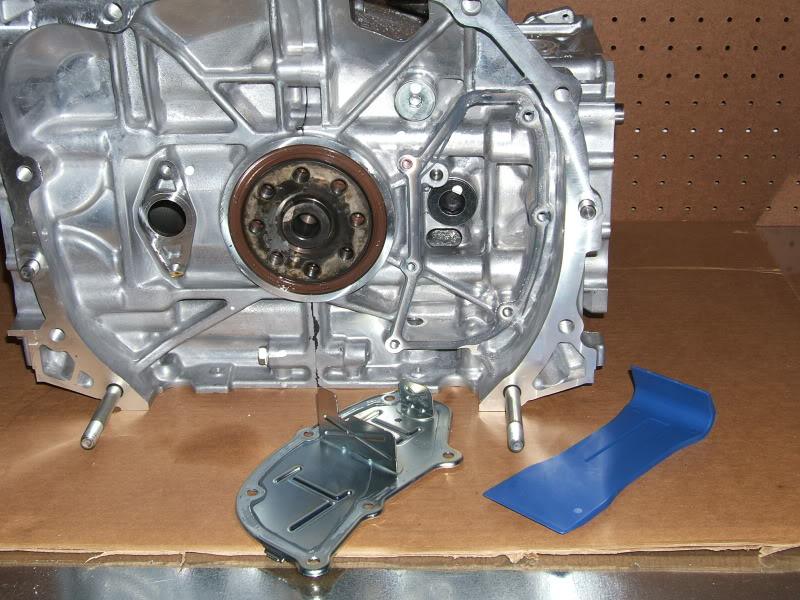
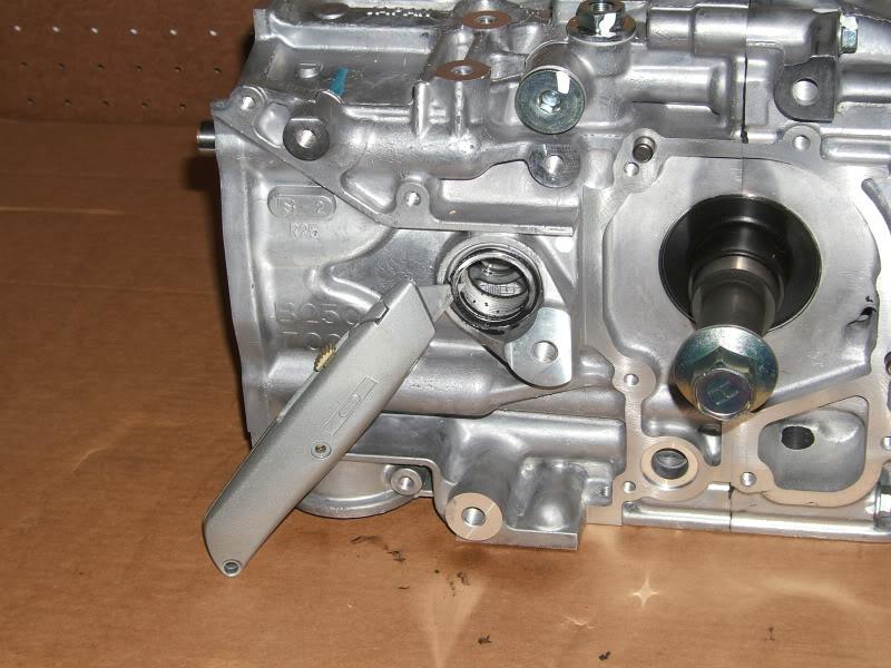
2. Remove the rear pan cover. It is held on by 6 screws which require a 4mm hexbit socket (or Allen wrench) to remove. If the screw head strips, drill a 1/4" deep hole through the center of the screw with a 7/64" drill bit. Use a #2 easy out and an adjustable wrench to remove the screw. To get the easy out to bite into the screw, gently tap it with a hammer from behind before applying any torque with the wrench. The pan itself is held on tightly by liquid gasket, but will come off easily with the right leverage. I used a nylon pry bar to remove the pan without damaging it (Picture 2). Once the pan is removed, you have access to the service hole plug for cylinder #3. (Picture 3).
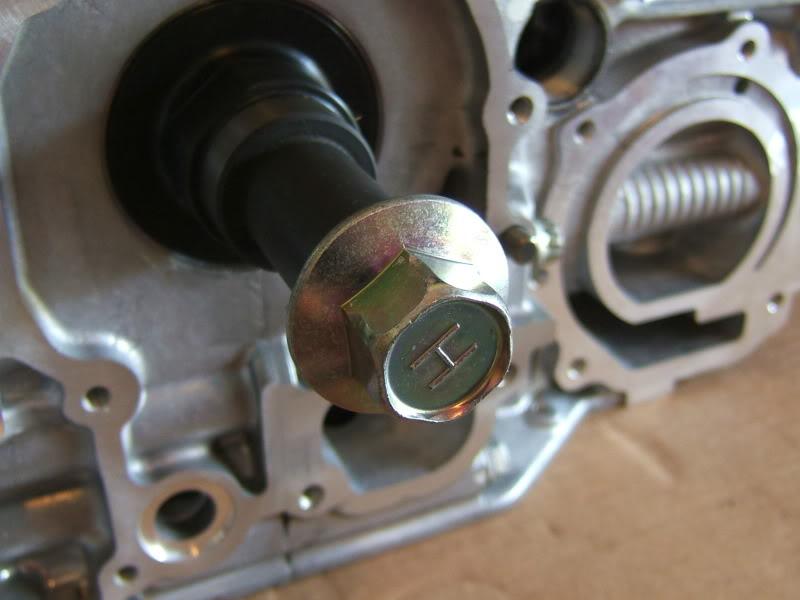
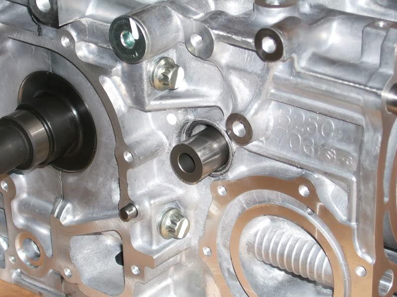
3. Remove the 3 service hole plugs with a 1/2" drive breaker bar and a 14mm hex bit socket. Lean on the opposite side of the block that you are pulling from as these plugs are difficult to loosen. Note that these plugs are assembled with liquid gasket and a steel ring gasket. Use a putty knife or razor blade to gently remove the steel ring gasket if it is stuck to the shortblock (Picture 2).
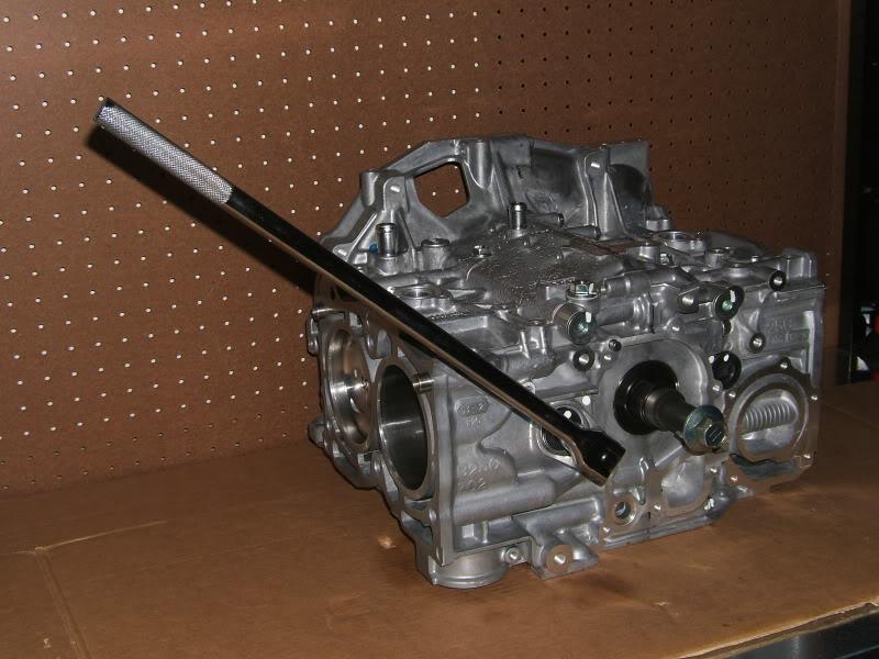
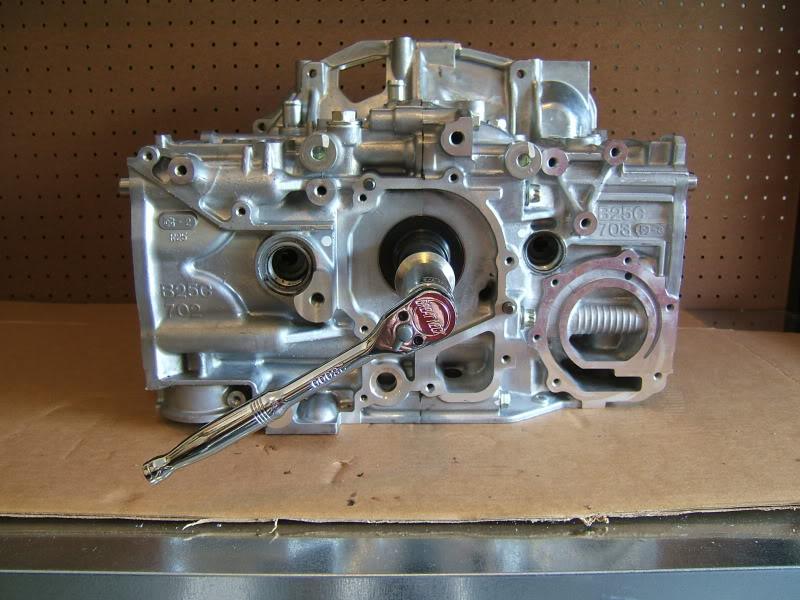
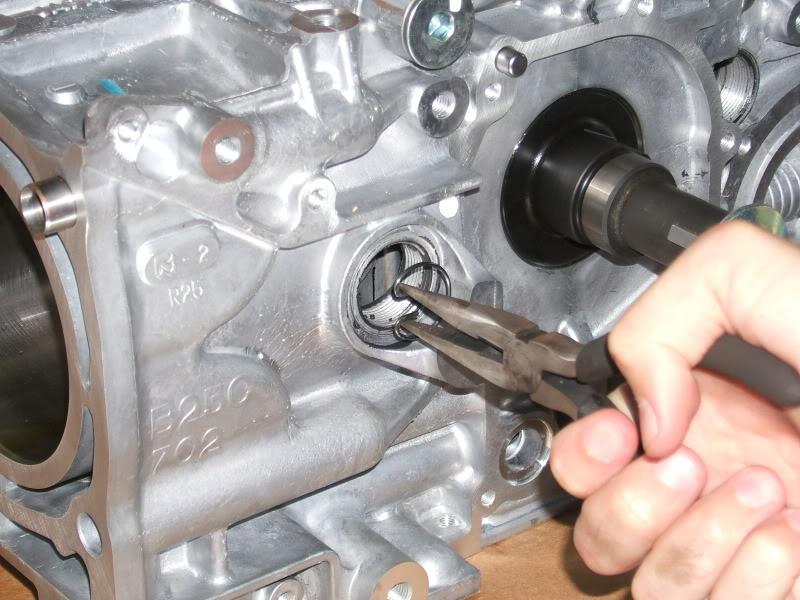
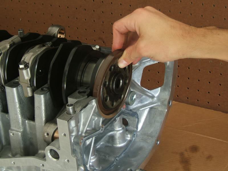
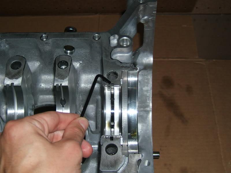
4. Rotate the crankshaft clockwise with a 3/8" drive ratchet and a 22mm (or 7/8") socket until the piston pins are visible through the #1 and #2 service holes at the front (Picture 2). Remove the retaining clips with a pair of needle nose pliers (Picture 3). Be careful and make sure you have them held securely before removing them. If they fling off your pliers while inside the block, you'll be fishing them out before proceeding.
5. Here is where methods can vary. The 07 STI Service Manual says to remove the piston pins from service holes #1 and #2 using the piston pin remover (Special Tool 499097700). Repeat step 4 again for the rear service holes. Then remove the piston pins from service holes #3 and #4 using the piston pin remover. The helpful links in the first post of this DIY show some fabricated tools that can be used instead of the piston pin remover. The pistons should remain in their cylinders so long as you do not rotate the crankshaft a full rotation after removing piston pins #1 and #2. The 07 Service Manual states that the pistons should remain in the cylinders when the block is separated. I'm going to use an alternate method starting in step 6. You might encounter some of the problems I encountered even if you follow the Service Manual, but steps 6,7, 8, and 9 will help you solve them.
6. Take a long and thin flat head screw driver and put a piece of electrical tape over the tip. This will help protect the shortblock components from scratches. Guide the screw driver through service holes #3 and #4 to reach the back of pins #1 and #2. Make sure that the flat tip of the screwdriver is seated securely against the piston pin and not the retaining clip. Tap the back of the screwdriver with the palm of your hand to force the pins out the other side. If the rods prevent you from guiding the screwdriver through, you may need to turn the crankshaft. Double check that the pins you are removing are still lined up with the service hole if you turn the crankshaft. Also, turn the crankshaft slowly if you've already removed a pin because that rod will be touching the cylinder wall. If you feel that it is binding, rotate it gently counterclockwise. Don't force the crankshaft if it doesn't want to move. Once pins #1 and #2 are out, repeat the same process for pins #3 and #4 after removing retaining clips #3 and #4. Mark the pins with a sharpie so that you know which cylinder/piston they came from. Depending on how you do this, you may run into a few issues and find that pistons start popping out and need to be removed. I removed all 4 of my pistons before separating the block, but this is not absolutely necessary. Steps 7, 8, and 9 cover the different scenarios you may or may not encounter when removing the pistons.
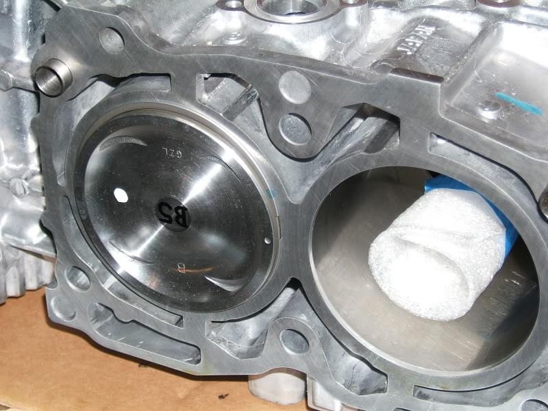
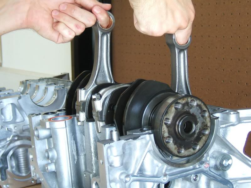
7. When the crankshaft is rotated during step 6, pistons may start popping out. This happens if the rods catch the piston after the pin was removed. Carefully pull the piston out if this happens (Picture 2). Mark the piston with a sharpie to identify which cylinder it came from. Wrap the tip of the rod with packing material to protect the cylinder walls as you rotate the crankshaft (Picture 3). If you wrap the rod too far up, it may pull into the crankshaft and feel like it is binding.
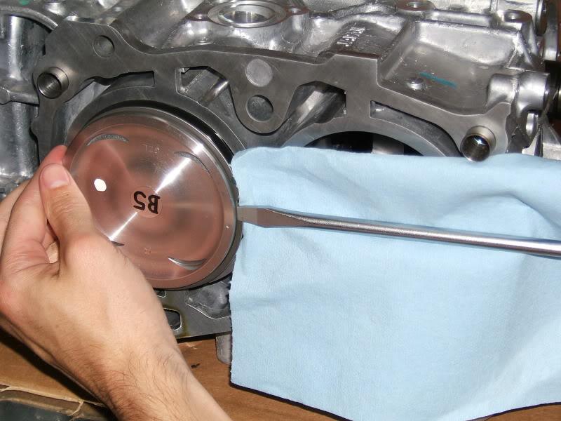
8. You might encounter a problematic piston. This one was sticking out enough to allow the ring to protrude. However, it was tightly fit to the bore and it was not exposed enough to allow me to pull it out by hand. I tried to rotate it slightly so that the rod could push it out the rest of the way, but this didn't work either. I finally resorted to inserting a flat headed screwdriver tip into the top ringland gap while supporting the piston with my hand on the opposite side. I also put a rag between the screwdriver and the shortblock surface to prevent any scraping or damage to this surface. I very carefully and slowly maneuvered the piston out with leverage. Step 9 shows a better way to remove a piston like this.
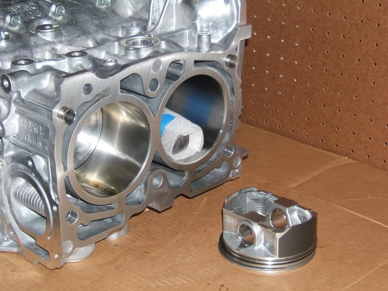
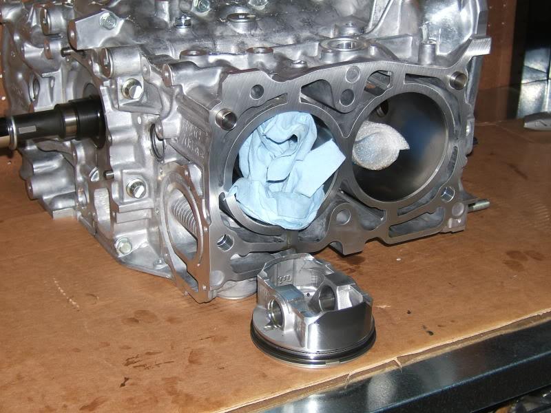
9. You might encounter a piston that does not want to come out at all. In this case, the rod and piston align so well that the rod will not push the piston out when the crankshaft is turned. To remedy this, take a rag or cloth and clean the service hole for this piston. Then take 2 to 3 rags and wind them up so that they can fit into the service hole. Stuff 2 to 3 rags in the service hole towards the back of the piston and then turn the crank. The rod can't align with the piston when the rags are in the way and it will force the piston out.
Separating the Block:
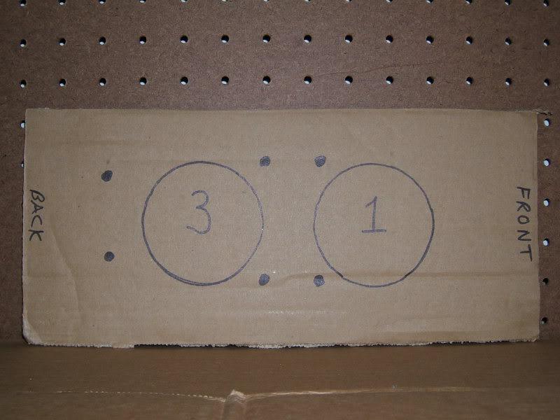
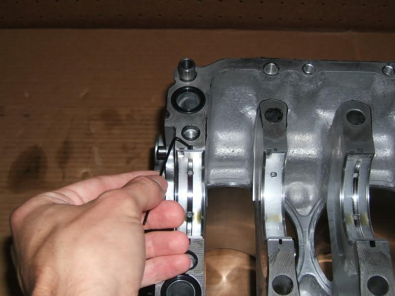
1. Make a cardboard template of the bolt pattern for the side with cylinders #1 and #3. The service manual calls this the RH or right hand side. Prepunch the holes with a Phillips head screwdriver. The template will make reassembly easier. Remove the 6 bolts (Picture 2) with a 1/2" drive breaker bar, 1/2" to 3/8" drive adapter, socket extension, and 12 point 12mm socket. Make sure the extension and socket are long enough to give the breaker bar good clearance to the machined surface. The bolts are not easy to reach and remove once they are loose. Use a telescoping magnet to pull them out (Picture 3). As you remove the bolts, punch them through the template (Picture 4).
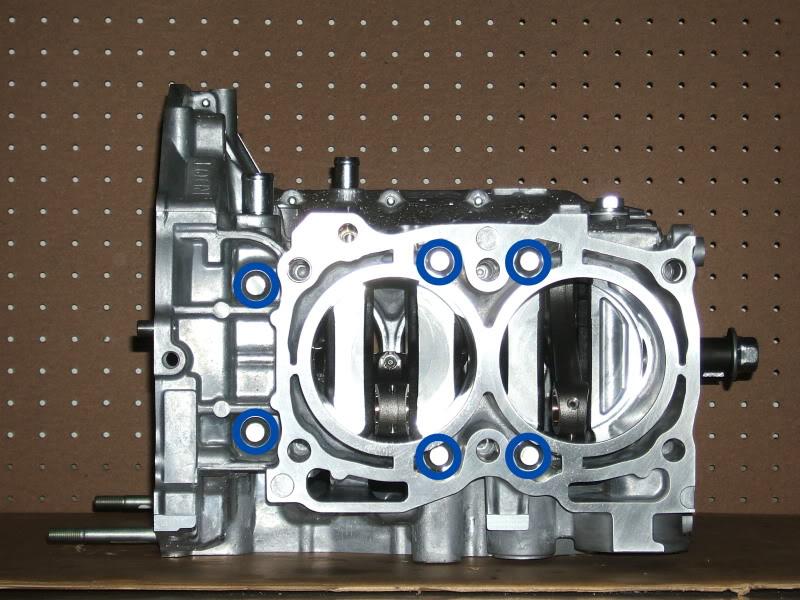
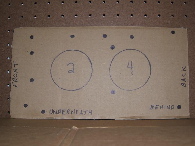
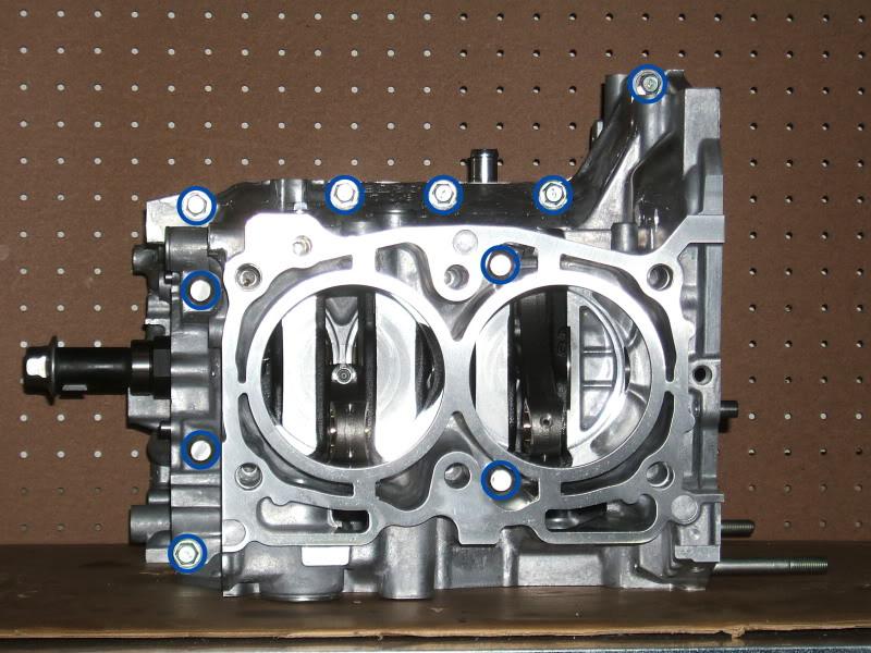
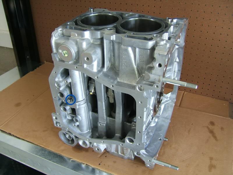
2. Make a cardboard template of the bolt pattern for the side with cylinders #2 and #4. Add the "Underneath" and "Behind" locations to the template. The service manual calls this the LH or left hand side. Prepunch the holes with a Phillips head screwdriver. The template will make reassembly easier. Loosen the 10 bolts (Picture 2) with a 1/2" drive breaker bar, 1/2" to 3/8" drive adapter, socket extension, and 12 point 12mm socket (Picture 3). On the bottom left bolt, I recommend using a 6 point 12mm socket instead of the 12 point since it gives you more contact surface. Make sure the extension and socket are long enough to give the breaker bar good clearance to the machined surface. Do not loosen the bolts more than 1 turn. Do not remove these bolts.
3.
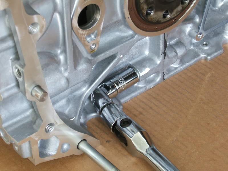
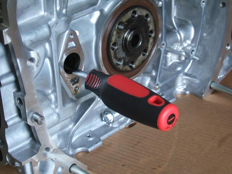
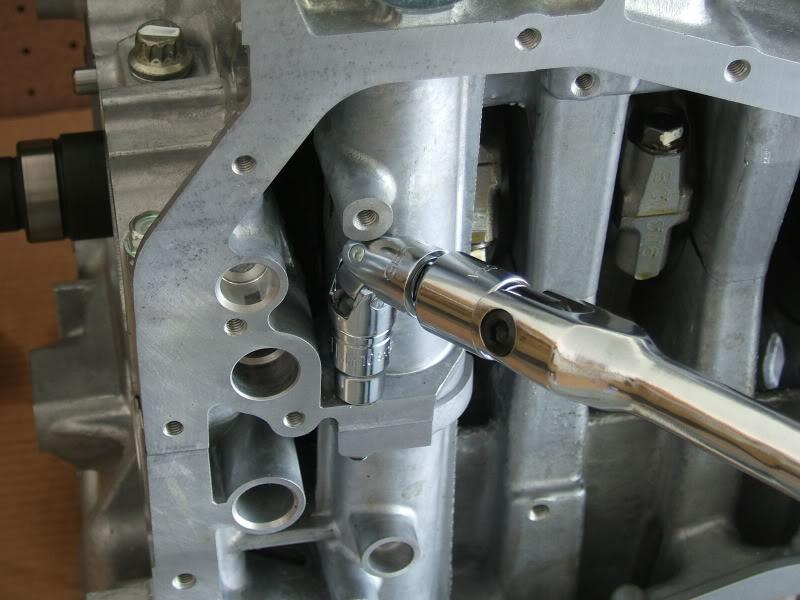
4. Turn the shortblock on its side with cylinders #2 and #4 facing up. Locate the screw underneath and remove it with a breaker bar, swivel adapter, and ...
5.
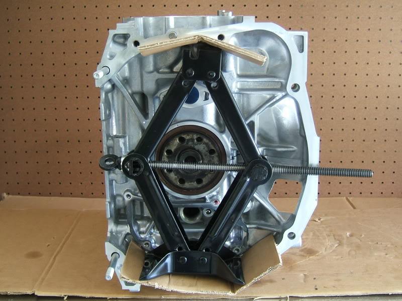
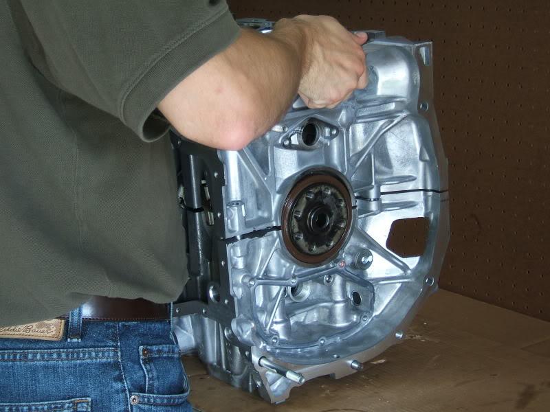
6. Place a couple pieces of cardboard on the inside of the shortblock so that the jack base and crown will not damage the aluminum surface. Use the OEM jack to separate the 2 case halves. WARNING: You only want to start the separation. Do not continue turning the jack screw once you see a thin gap between the metal. Once you have this thin gap, take a rubber mallet and tap the metal near the seam at the front of the two case halves to help loosen the liquid gasket. Be careful not to hit or damage any machined surfaces. Optionally, place cardboard against the metal to dampen the blow of the mallet. Then remove the jack.
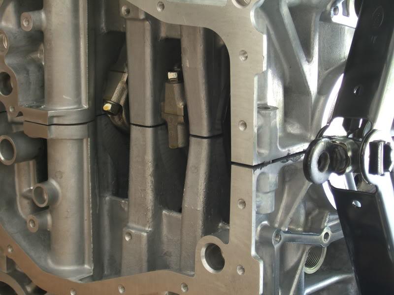
7. Separate the two case halves by lifting straight up on one side. If you start lifting and the case halves get ****ed to one side, push them back together and try again. You can take some precaution here and have a friend place some cardboard against the metal where the rods are going to fall. I let mine fall and they were fine, but it's still a good idea to protect the surfaces.
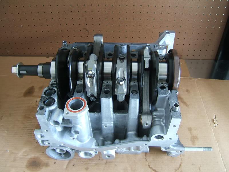
Remove the Crankshaft, Bearings, and O-rings:
1.
2. 1.5mm Allen, 3mm Allen
3.
8-21-2009
Remove the Rods from the Crankshaft:
Top of the 2's on the ring faces the front. 4's on the rods face back.

Nice details
Posted by Diggymart on 10/12/21 @ 2:09:23 PM