You must be logged in to rate content!
15 minute read

Install a remote start car alarm in an sti
Compliments of thundercamel @ iwsti.com
2-8-2009
Ya hey der! I just installed a Viper 5900 on my 05 sti, and took a few pictures along the way. This is mainly to show you where the wires are in the car that you need. iwsti has given me so much information in the last year, and I’d like to return what I can help with. If you have a different year, or different alarm, you will have some differences of course.
I got the viper 5900 just before the 5901 came out. The only difference is the remote I believe. I got it from here, but it was $195 plus $13.63 shipping. Do a google shopping search.
Also:
Trunk release solenoid
Vehicle tilt sensor
Glass break audio sensor
Remote start bypass (leaves immobilizer intact, only activates for the remote start.)
Tools:
Screwdrivers
Socket set
Soldering iron
Wire strippers (see note below)
Electrical tape (good stuff, like scotch super 33+)
Digital multi-meter
Zip ties
Diagonal cutters
Electronics knowledge. If you burn something out on your own car, it’s your own fault.
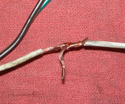
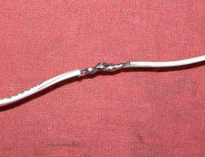
I like these wire strippers:

They fit in tight places, and strip the factory wire easily, without cutting it. Then you just wrap your wire around it, solder, and tape. The brand is Garden Bender I believe, and I got them from Menards.
Here’s someone else’s picture, of just making a butt splice.
Time estimate: A long weekend, if you have all of your connections planned out with electrical diagrams ahead of time, and you’ve done a remote start car alarm before. I did this in my cold garage, with a propane heater pointed at the open driver door. I was really slow, making sure I did everything perfectly.
Use the wiring diagrams to find all the wires you’ll need to connect to. I used these basic ones, which have 90% of what you’ll need to know.
These links used to work, but the source has gone away.
Download 2005 STI diagrams here
The full diagrams are in the service manual, here:
http://www.iwsti.com/forums/2133157-post15.html
They are huge, slow, and confusing at first. Make sure for the engine controls part, you are in the sti section, not the normally aspirated or turbo section. These diagrams showed me the rear defogger, and which pins on the ecu was for the tach and neutral safety wire. The find function helped a lot.
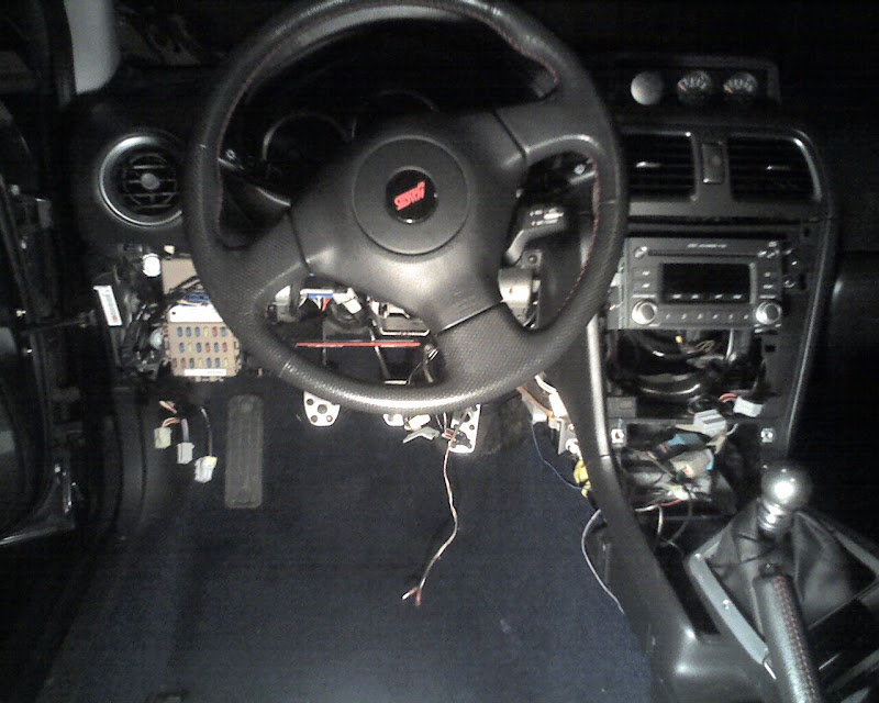
Where did I start? With the drivers seat. There’s a 14mm bolt at each corner, with plastic covers over the rear two. The rear inboard bolt is bigger than the rest, and I think the rears have big washers, while the fronts don’t. Under the seat is a clip for the seatbelt dinger, and one for the airbag. The airbag one is not so fun. Use a skinny flat head to push the green slider in. After the seat was out, I put down the two end pillows from my couch on either side of that metal hump, so I could lie down and work under the dash upside-down. It was actually kind of comfy.
Take off the under-dash trim. This guy shows it well:
http://www.iwsti.com/forums/how-inst...ory-alarm.html
but basically, it’s a screw at the left and right bottom corner, and pull the top towards you. Unplug the wires. There’s also a metal plate, with two 10mm bolts.
I mounted the control unit, immobilizer bypass, and sensors under the stereo behind the HVAC, so I took off the shifter and HVAC trim also. Shifter trim just pulls up from the rear, and there's a snap in the leather around the shift knob. HVAC trim has two screws on the bottom, and pulls forward at the top.
Time for wiring. Double check all of your connection points with a meter, to confirm that they are the wires you’re looking for. For example, the door switch wire should show 12 volts until a door is opened. Start with the heavy gauge wires. Why? Because they’re large and in charge.
High current power in: White
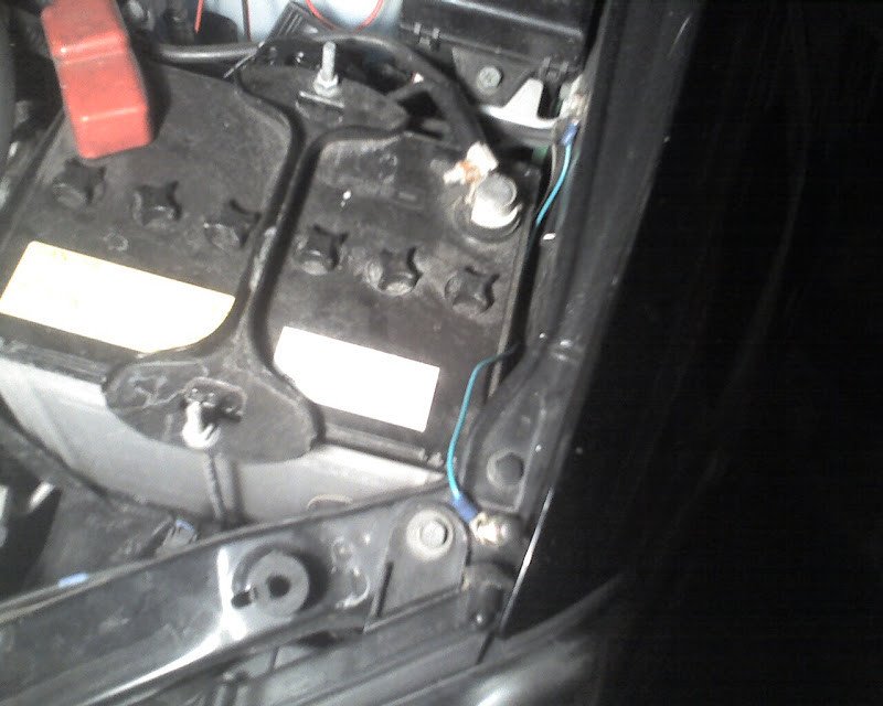
There’s a fat white 50amp wire that drives the key switch. Lucky for us, there’s a parallel branch that goes to the bottom of the relay holder. It feeds a little 10amp fuse there, for part of the ABS system. I taped off the white wire there, behind the relay holder. I also used this to the constant power in to the control unit.
Starter output: Yellow
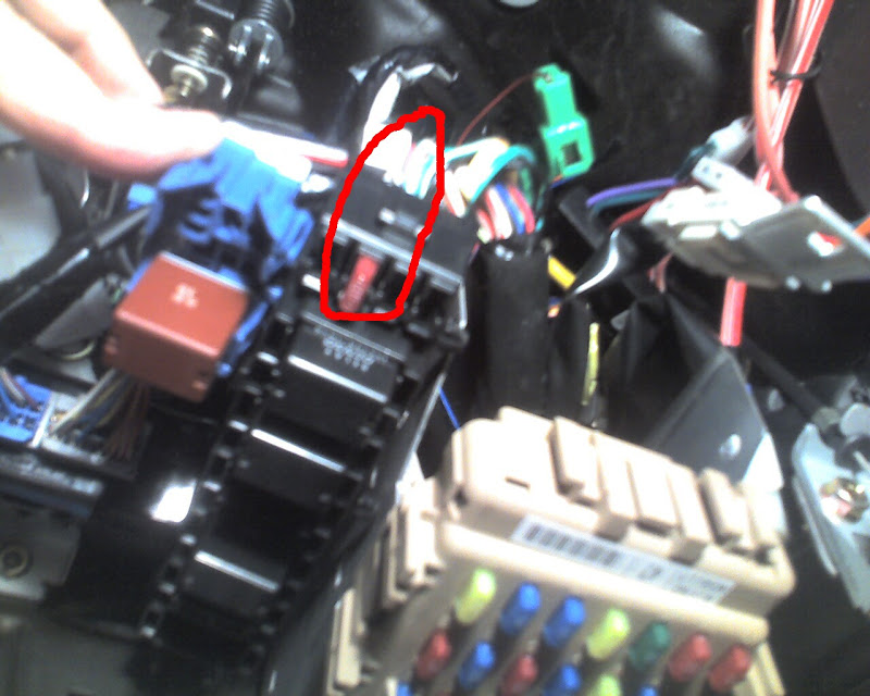
At first, things were looking tough, because of the starter interlock relay. The key switch feeds the positive side of the coil, and the clutch switch feeds the negative side of the coil. Once I found out that this relay is in the same relay holder next to the fuse box, things were easy. The best way to do this is to connect directly to the interlock relay’s output to the starter. It’s a thick yellow wire towards the top of the relay holder. This is the only factory wire that you actually cut, for the starter kill and anti-grind to work. The alarm has a starter output to starter, and a starter input from ignition for each side of the wire you cut to go to.
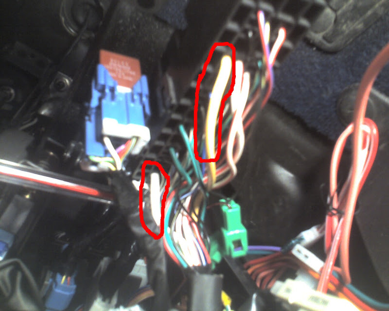
In the picture, the bottom circle is the white constant power in.
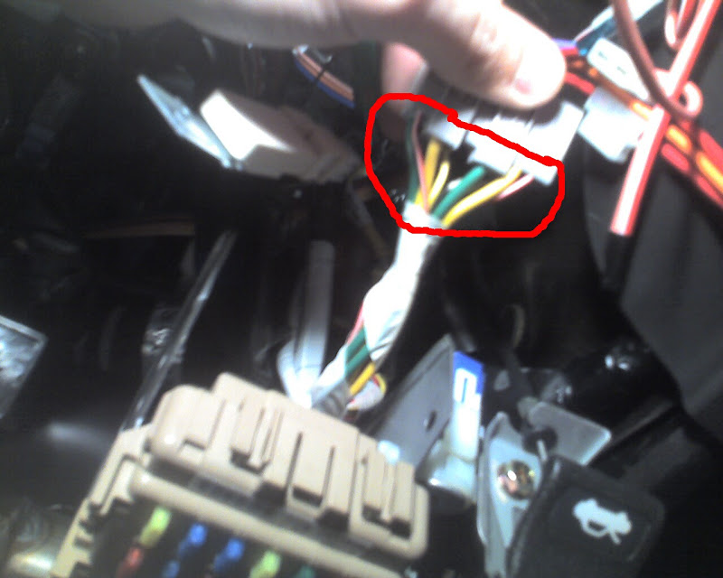
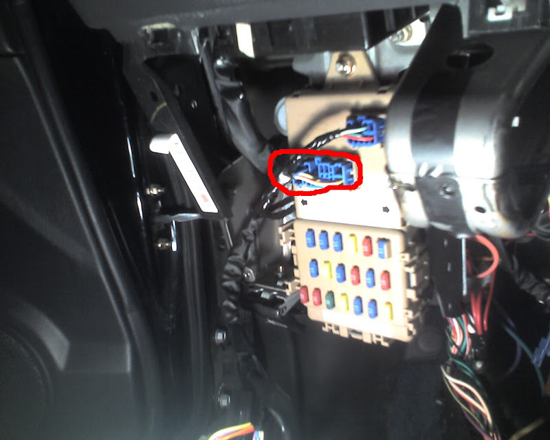
Accessory output: Yellow
Next to the relay holder, is the fuse box. At the bottom of the fuse box, is it’s input, which comes from the ignition switch. Unplug the input, and either of the yellow wires (they’re in parallel) is what you connect to.
Ignition output: Green
Same thing, but either of the green wires.
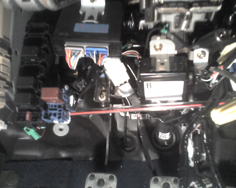
The viper uses a satellite relay box for the heavy gauge wires. I zip tied it to a bundle of wires up behind the hood release handle. All of my wires were no more than 6 inches to their destinations. Now for the rest of the wires, 80% of the wires I needed were already at the keyless entry unit. It’s the black box above the fuse box. Run your harness nicely over to it, and pull back wires one at a time that go somewhere else. I did mine up over the steel bar in the dash.
Side note: Some of the wires that you use at the keyless entry unit also run to the integrated unit. Don’t bother with the integrated unit, because any of the wires you could use there, also run to the keyless entry unit, plus more.
Ground input: Black
I taped off the ground going to the cigarette lighter. This one you might want to run a wire from the lighter, and have a wire nut in a easy access location during the install. More things later will need ground; solder it when you’re done.
Trunk input (-): Yellow with red stripe
At the keyless entry unit. The door unlock is the same color, so confirm with the meter that you have the wire you want.
Door trigger input (-): Yellow
At the keyless entry unit. If you look at the diagrams, this is the wire for all the doors except the drivers door. If you look at the diagrams closer, you’ll see that both wires run to the indicator in the gauge cluster that show when the door’s open. The drivers door is separated by a diode, and pulls the yellow wire low when it’s open anyways. In the end, this wires shows low when any door is open.
Domelight supervision output:
Not needed! When you hook up the lock to the keyless entry unit, that goes to the integrated unit, the integrated unit drives the locks and the dome light already.
Light flash output (+): Light green with black stripe, and black with green stripe
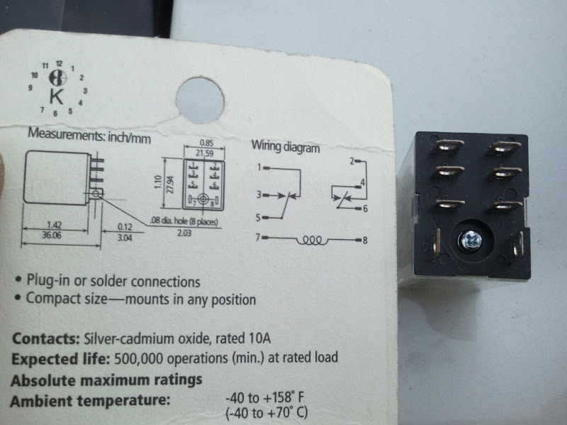
On this one, you have a decision to make. The stock keyless entry unit flashes the turn signals, not the parking light. Most alarms are connected to the parking lights, but I decided to keep using the turn signals because it looks cool, and I didn’t have to go looking for the parking lights wire then. To use the turn signals, you will need a double pole double throw relay. If you don’t want to use one, use the diagrams, and hook it up to the parking lights.
The two wire colors I mentioned above are for the left and right turn signal. To keep them separate, you will need a DPDT relay; refer to the schematic below. Connect the 2 normally opens (terminals 3 & 4), to the left and right turn signal output wires, one wire for each terminal keeping them seperate. Connect the 2 common terminals (5 & 6) together, to the light flash output from the alarm unit, and also to one side of the coil (7). The other side of the coil (8) goes to ground.
Side note: I don’t think the turn signal bulbs are meant to be run more than 50% duty cycle, they might get kind of warm. When the viper is remote started, the lights are on most of the time, but they do flash about every 2 seconds, and I think they’re off long enough to let the filaments cool down.
Second unlock output (-): Yellow with red stripe
At the keyless entry unit. The trunk input is the same color, so confirm with the meter that you have the wire you want. This is for progressive door locks, like the stock keyless entry system. On the viper, the second unlock output is what triggers the second time you press the button. Connect this to the yellow/red wire, which unlocks all the doors.
Unlock output (-): Orange with black stripe
At the keyless entry unit. This wire runs only from the keyless entry unit, to the integrated unit, to unlock the drivers door only.
Lock output (-): Red with white stripe
At the keyless entry unit. The integrated unit drives the locks, so you don’t have to worry about this being a high current wire.
Horn (-): Red with green stripe
At the keyless entry unit. This drives the relay that drives the horn, so it is not high current.
Brake shutdown input (+): White with black stripe
At the brake pedal.
Hood pin input (-):
I found a hole already here, and connected the ground to the grounding point, so I didn’t have to sand the paint off. It’s kind of visible from outside though, so you might want to move it inwards if you’re that worried about security.
To get the wires through the firewall, there's an awesome rubber plug between the clutch and brake pedal. Once you push the wires through, you have to go under the car to pull them from the engine compartment side.
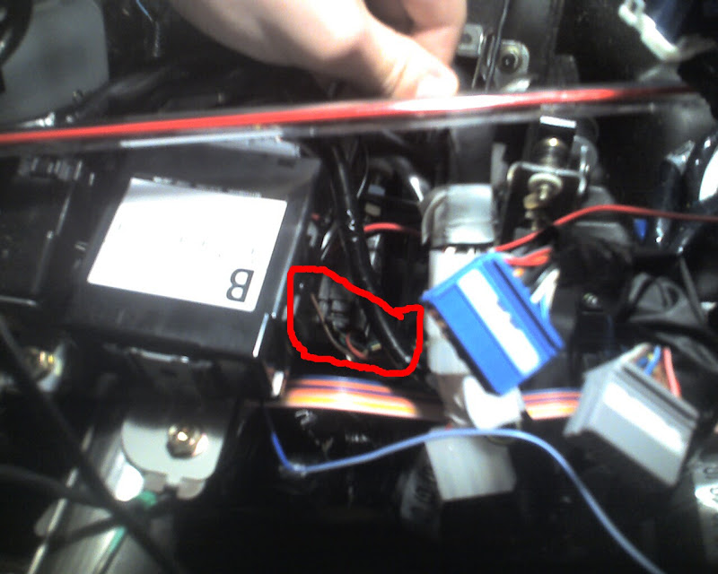
Rear defogger output (-): Blue
The relay for the rear defogger is inside of the fuse box. There’s a plug on the front top with a blue wire that drives the coil of the relay.
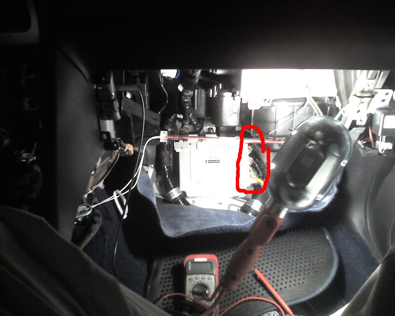
Tachometer input (ac): Green
This is on the ECU, that goes to the tach on the dash. If you search the service manual diagram for “b134” you will find that’s the bottom connector on the ecu. It will also show a pinout of the plug. The ECU is located under the passenger kick panel.
Neutral safety input (-): Green with black stripe
This is on connector b137 at the top of the ECU. I think the 04 (which I thankfully don’t have) has the logic reversed, and you need a relay to flip it.
.
Factory beeper (-): Red with yellow stripe
At the keyless entry unit.
An extra thing I did in this install, was to keep the factory keyless entry beeper working like normal. I wanted the lock/unlock to chirp the beeper, but when the alarm goes off, have it switch to the siren, and pulse the horn. If there was a way to get the viper to chirp the horn, without chirping the siren, this would have only required one relay. As it turns out, I used two SPDT relays and a diode. Here’s the diagram, courtesy of mspaint:
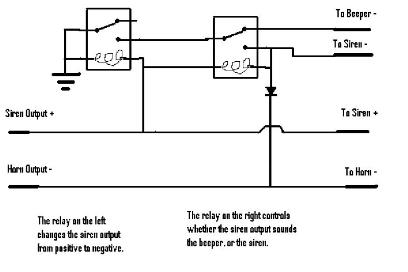
The first relay is just to get a low output whenever the siren output from the alarm chirps, because the beeper requires a negative trigger.
The second relay switches from driving the beeper to driving the siren. It’s triggered whenever both the alarm’s siren and horn output are on. It also latches when it’s triggered, and stays latched until the siren output turns off.
The diode is so once the relay’s latched, it won’t keep the horn on constantly. The alarm will keep pulsing it.
In the end, it worked exactly like I wanted it to. The only thing I wish, is that it had a variable duration for the chirp of the siren output, like it does for the horn output. It’s a much quicker beep than the factory system.
The factory immobilizer bypass 556u / 556uw was required for the RFID key. Everybody mentions that you’ll need this, but no one ever said what exactly on it you’ll need to hook up! All it needed was power/ground, the status output from the alarm, which engages it when you remote start, and the antenna output ring. Don’t bother trying to wire this into the factory antenna, and don’t over do this antenna mounting either. It fits great over the whole cylinder with the plastic lighted cover. Just slide it back far enough to be behind the steering column plastic shroud cover, and you won’t ever see it, or have problems with it not being in range. It’s directly on top of the factory antenna at that point there. The bypass module did not need the key sense input, or the true ignition input, though I’ll admit that I haven’t tried this yet with 2 rfid keys, since I only have one. Will fork up the cash for a dealer copy later, and I can only start my car with the remote till then J and have a plain copy for the ignition.
I put the led in the left blank by the IC spray button, and my antenna behind the mirror, with the wire tucked behind the roof and a-pillar trim.
I also did the glass break audio sensor, and the tilt sensor. The trunk pop solenoid I’ll do when it’s warmer outside.
If you have any questions, post them up instead of pm’ing me, so others may learn!