You must be logged in to rate content!
19 minute read
Electric power steering
Compliments of Ae95/4agze @ toymods.org
5-15-2013
At request I post my how to electric power steering conversion. This was done on my 1992 corolla all-trac wagon. Why some ask? Well the car recieved a engine upgrade. 4agze from a 89 aw11 mr2 and flogging a sc14. Anyone fimilar with this engine know the supercharger sits where the powersteering pump was. While my past 91 corolla with a "z" engine i just drove it pump removed. I found after picking up the wagon that i would liked having power steering. So began one of the stupid little projects we get are selves into.
I originally post this modification/upgrade in my build over at the alltracwagon.net forum. 4agze build - All-Trac Wagon Network
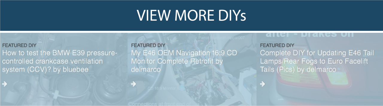
This is the EPS (electric power steering). First off there are two types of EPS i have encounter over the years. First is the style that use a electric hydraulic pump. These i have seen on sw20 2nd gen mr2 and mini coopers.
This is a pump from a sw20.
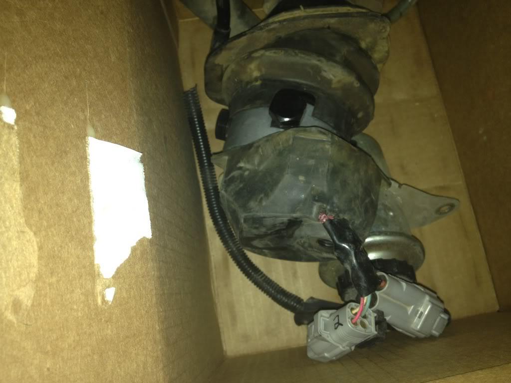
This the ecu for the sw20. I should note i have this setup for sale if any one in the U.S. what it.
The second type is full ellectric. Where the electric motor is attached to either the steering column or steering rack. While there are many different versions of these. I will only cover the 2004 and new toyota prius and 2006 toyota yaris. I will note that this conversion can be done completely using parts from a 2006 toyota yaris. The most important part is the EPS ecu needs to come from a yaris that does NOT have abs. The one quirk is that the ecu looks for both the rpm signal and wheel speed signal from the can network. The eps ecu will not provide assit tell it see the either one of these signal. I did look into reproducing the can signal but it would not be cost effective. This is where the NON ABS ecu provides a work around. The non abs ecu does not get its wheel speed signal from the can network. It get the signal from the instrument cluster in a standard 5v pulse. The only quirk with this is tell it see a pulse the ecu does not provide assit. Once it has see the speed signal it will continue to provide assit tell the ignition is cycled off. I did look it to building a small pulse generator and circuit has a work around but after driving the car with out the work around i found that it did not bother me enough to build the circuit. I find that when backing out of a parking stall the assit will start just after i need to start turning the wheel.
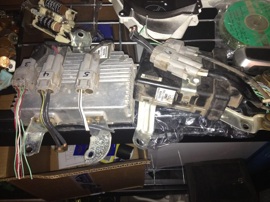
bottom is my stock steering column from a 1992 ae95 corolla alltrac wagon. The column is a tilt column.
The top is the EPS column from a 2004 toyota prius.
I started by disassembling my stock column.
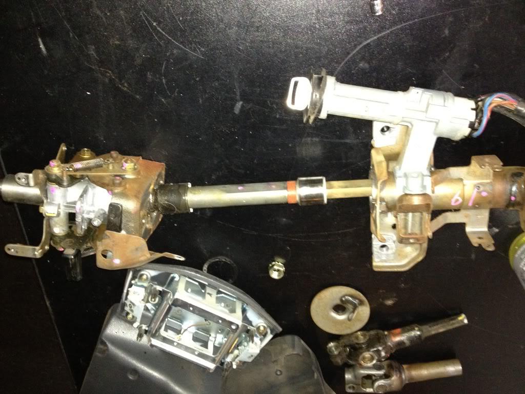
sorry my pic are not exact detail on tear down. But if you are attempt this conversion i would hope you would have the skills to figure out how the column comes apart.
The 2004 prius column has two parts, the top tube is slide over the tube that is attched to the motor housing. The outter tube is crimped to keep it from sliding apart. I cut the crimped part with a die grinder and then was able to slide it off. The above pic is the column still together and i should note the upper tube has the factory mounting brackets attached to it.
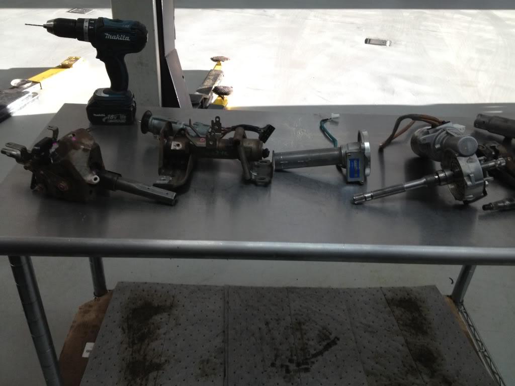
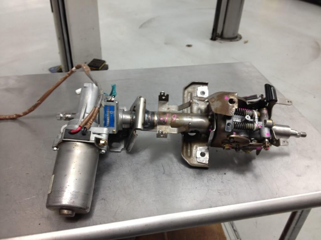
this pic is laying everthing out to work out how eveything will go together. The left part is the stock tilt mechanism, note the shaft sticking out. The next part is the main stock housing with the stock mounting brackets and ignition cylinder/switch. Then the prius part the first tube houses the torque sensor.(please take care to not damage this sensor.) the torque sensor is what to ecu uses to determine direction and amount of assit required. there is also a bearing in the housing. Next is the motor and gear housing. You will note this has a long shaft sticking out, this shaft hold the teeth that torque sensor looks for. On the other side is the output that will go the steering rack. The last part and not shown in the pic was the upper shaft from the prius, this shaft splines with the shaft coming out of the motor assembly. This shaft was measure ti figure out the length need, then the shaft coming off the original title mechanism. I had to finish removing the shaft from the mechanism. Once removed and measured out i cut the two shaft and wielded them together.
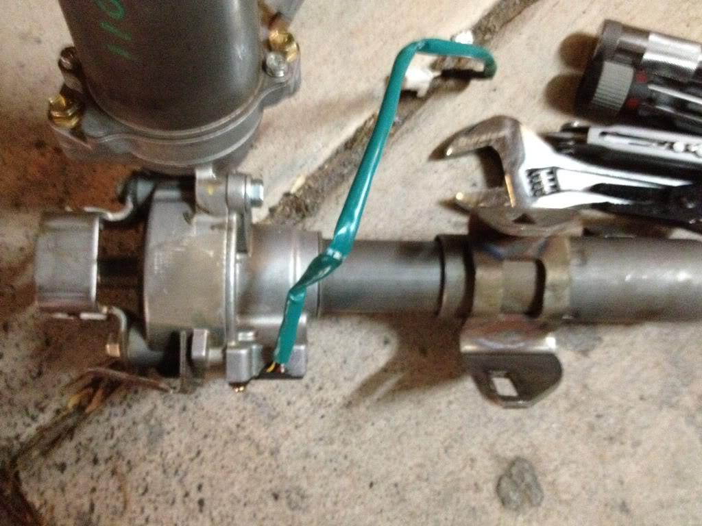
from the joint to the left is where the steering wheel mount. To the right of the joint first you will notice a collar with a notch. This notch is for the steering wheel lock when the key is out.
Necked is the housing which also was measued out cut and wielded together. But before it was wield i had to remove the torque sensor.
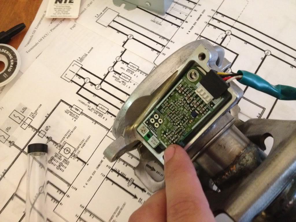
first i had to desoilder the circuit board. This is the four larger holes at the top of the circuit board above my finger.
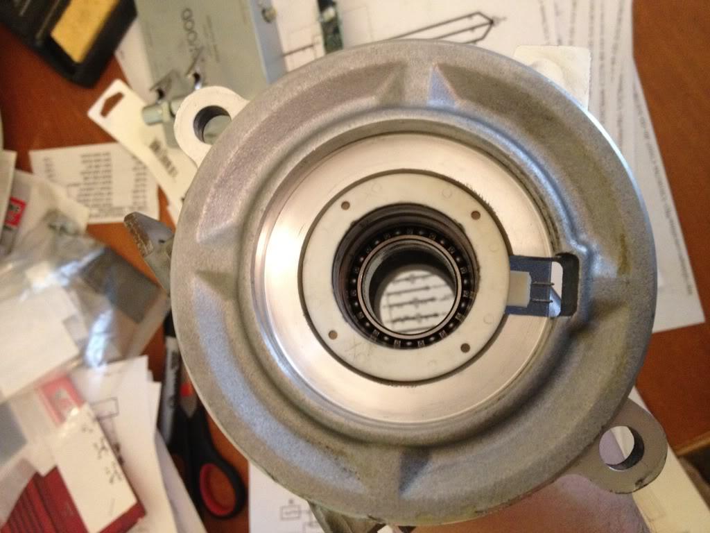
then carefully pulling the white cylinder plastic piece out. You can also see the bearing. This was left and seems to have servide the heat of wielding.

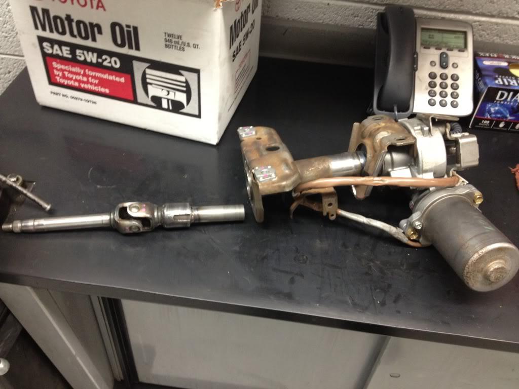
the housing all wielded up on the right side. I had to remove the lower mounting bracket and wield it back on with the EPS housing. Once wield i reinstalled the torque sensor and soilder the circuit board. Then install the upper shaft in the tilt mechanism and remounted the mechanism to the main housing.
All finished and ready to install in the car. I should note that make sure you test fit and measure to make sure the motor will not hit anything once installed.
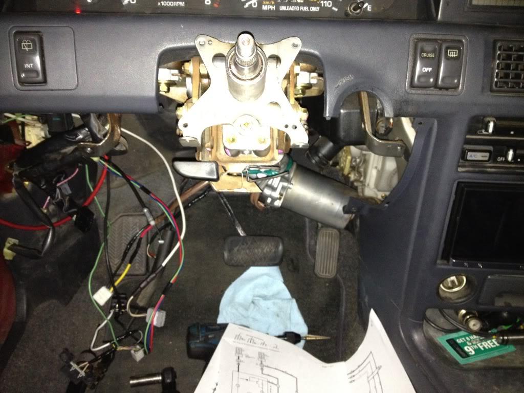
And here it is in the car.
Now that the easy part is done![]() on to the hard part wiring. I should note that when you order your ecu make sure to get the wiring harness pig tails and connectors. With out them you may have a fun time locating the connectors (i have already tried order in the connector from toyota and while i had the part number toyota could not order them in) or end up soildering the wires striaght to the ecu.
on to the hard part wiring. I should note that when you order your ecu make sure to get the wiring harness pig tails and connectors. With out them you may have a fun time locating the connectors (i have already tried order in the connector from toyota and while i had the part number toyota could not order them in) or end up soildering the wires striaght to the ecu.
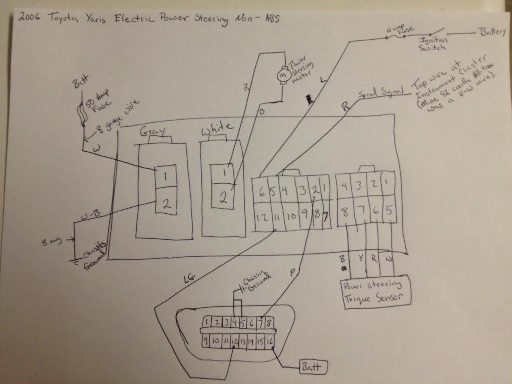
First you will need to locate a location to mount the ecu, which will need to be close to be able to plug the harness from the column. I mount mine to the dash main brace to the right of the steering column. Sorry i did not take a pic of it mounted. Next will be building a high amp circuit. For this i used car audio amplifier power wire of 8awg, and a 50 amp fuse. The ecu has four connectors, one for the main power which is 2pins, a second for the motor also a 2pin connector. Then the torque sensor connector and last the main connector. The connectors for both the torque sensor and motor should just need to be plugged in. The high power two pin and main 12 pin connectors will need to be wired up. The high power will be the ground and 50 amp fused wire. Note the ecu has its own high amp relay so the 50 amp wire does not need to be switched. On the main 12pin connector will use only 4 pins, they will be pins 2, 5, 6 and 11. Pin 6 is the switched 12v power with 10amp fuse, this needs to be switch from the ignition switch. Pin 5 is the speed sensor signal wire. This need to be tapped to a 5v pulse generated signal. My ae92 corolla all-trac has a speed sensor built into the instrument cluster. I should note my car produces a 12v pulse but the eps ecu has fuctioned find despite the higher voltages. If your car does not produce a speed signal then a google search for a speed sensor adapter for aftermarket cruise control should work. The last 2 pins may or may not need to be used. If you bought both your ecu and column from the same vehicle then the torque sensor should still be calibrated and it should be plug and play, also some mix matching of columns and ecu may still function with out a problem. If not or if down the road there is a problem and the torque sensor need recalibrating, then these two pin will be need along with a dlc 3 connector. Pin 2 is the "SIL" this is the serial communication wire to go between the scan tool and the ecu. Pin 11 is the "TS" and this is the ecu diag pin. When this pin see ground then the ecu will communicate with the scan tool. The dlc3 connector is only needed if you need to connect a scan tool.
6-26-2013
Ill look at doing this in the future to my GT4 (Celica Alltrac for you ![]() ).
).
It does make me wonder if the Yaris assist motor will be strong enough to handle the rather heavy steering on the GT4 though.
During my research i did come accrossed several people with stock corolla with eps that said they could under the right conditions get the system to hot, causing it to go into limp mode. Which is assist reduce to i bieleve 30% tell the ecu/motor cool back down. But from what i have found after i got mine up and running is a company in europe that makes little controlers that wire into the ecu so you can manually adjusted the amount of assist. (Welcome to the Rallywiz online store. - www.rallywiz.com - (Powered by CubeCart)) this way you can turn the assist down if you are racing. Has for my car i do not race it, i just want a little more power and i had the 4agze engine sitting around.
9-25-2013
The ecu I used is "89650-52140" it from a toyota yaris 2006 with out abs. I should note that this is usdm spec. The key during my research into this conversion is. First the ecu has to match the eps type. The first gen prius used the assist built into the steering rack. This type of ecu will not work the colmun style eps. The second is the ecu needs to have an analog speed sensor input. And not get its speed signal from the can network. The best would be to find an ecu colmun combo where the ecu powers up over a rpm signal.
My setup does not work when you start the car. But once it sees a speend signal then it powers on and works great tell i turn the car off. I have looked into build a small pulse generator device, That would come on when i first start the car to trick the ecu into powering up. But the more i have driven the car most times i bearly notice.
Feel free to ask any more questions. Also sorry if my explaination is confusing. I am writing this on my iphone on my lunch break. Also if you post wiring diagrams from the eps system you are looking at getting. I maybe able to determine if it will work.
12-18-2013
With the non abs ecu and the speed sesnor connected, watching the data list on a toyota scan tool i can see the system reduce assist has the speed increase. I do notice the speed is of by about 8 or 9 miles so the system reach the speed of lest assist earlier then if in a yaris. My only problems has been that it will not power up tell it see about two pulse from the speed sensor.
Which most of the time happens fast enough to not notice. But ever once in a while it does take long enough that it would be nice to have it just power up. My two ideas are, first to build a small pulse device that would create several pulse on start thus causing the sytem to power up. The second is to use and arduino can board, connected to a functioning yaris and record the can signal during start up the just replay the recording to the eps ecu can lines. This one might be a little more tricky. But from my reacher and undrrstanding of the toyota can system the eps ecu is just looking for the rpm signal from the engine ecm over the can network. Any ones thought on this would greatly help both me and anyone playing with this setup.
2-22-2014
First of MWP i am glade to see someone else taking on this custom setup!
Now i have been working on getting some way to duplicate the can network to get my setup to function at full capacity. While doing much research into this and greatly expand on my understanding on the can bus system. So to start i would like to explain a little about the can system. Robert bosch developed the can system back in the 80. By about 2004 most manufacturers adopt the can system. If you are looking into this mod i would suggest you do some research into and understand the can system.
The basic of the system setup is two communication wire twist together. Each end of both wires are terminated with a 120 ohm resistor. Then each of the ecu are wire has branch of the main.
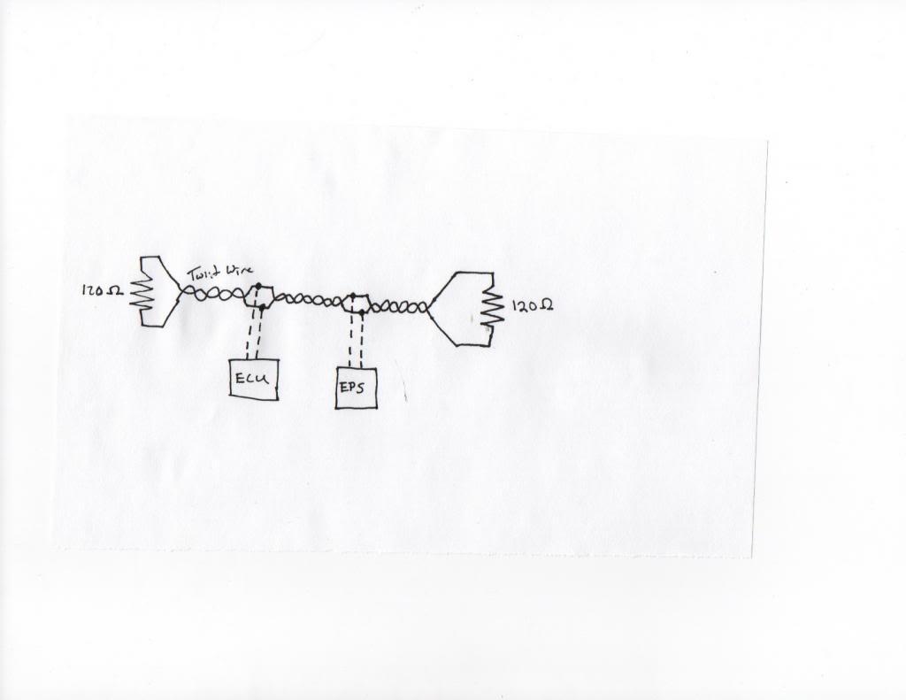
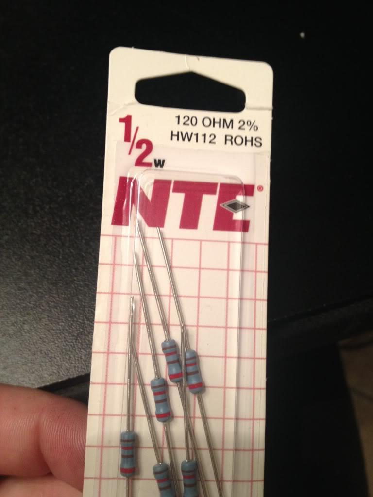
Sorry for my bad drawing. The 120 ohm resistor can be located on toyota vehicles in many location. Like a junction connector or even inside an ecu. The good thing is the yaris that my eps ecu is from, toyota put the resistor inside the eps ecu. So to wire mine up i only need a single 120 ohm resistor.
Make sure your resistor is after your wiring connection.
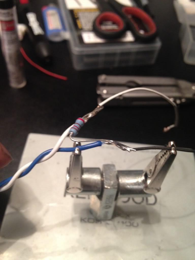
Then i heatshrinked over the resister and taped. There should not be much heat since its low voltage a wattage.
I did much research into how to duplicate the can network. My first direction was a arduino uno board with a can shield tranciever. The arduino uno i had and while researching which can shield to use i came acrossed a device from a company in england http://www.cananalyser.co.uk/candoauto.html
The cando auto unit spec looked to meet my needs and have software to boot. Which ment less time programing the ardunio.
So i order one. Getting it wired up and then started the fun part, programing it!
I found some great sites for information and one guy who actually had a youtube video of raw recorded can data from a yaris. http://fabiobaltieri.com/2013/07/23/...and-socketcan/
I going to jump in to technical which will make much more since once you research the can system. I was able to find the hex decimal code for engine rpm is 2C4 wheel speed is either 0B0 or 0B2. Since my setup non abs eps ecu has an analog wheel speed signal. I only needed the engine rpm on the can network so i will only go over how i programed the cando for this. The cando has 2 analog input that can be programed to then transmit a programable can data. It also can have ten static data points programed and continually repeted. When you get the software open there are four tabs. "Input view", "inut setup", "can transmit" and "can setup" first off we need to go to "can setup" and change the setting to 500kps to match the network speed of the can system. Then back to the tab "can transmit". Now has i said earlier the hex for rpm is 2C4. The data length is 11 bit. The dlc is 8. The information i used was ramdomly picked after much trial and error. Almost 3 pages of codes I tried. I could set a rpm in connect my scan tool and see the rpm but still now assist. After much frustration i finally realised that it was a setting i had wrong. It was how often i had it repetting the message. The end result looked something like this 2C4 8 06 8A 00 19 00 00 92 09 Repet rate 20 ms(milliseconds) . All this done and turned the car on and immediate assist. I still have not been able to drive the car and see if it feels bettter. Still working on some idle issues with the engine. I could however tell the assist was greater. Last thing to work on is connecting the can wiring to the dlc so i can see about changing the setting for the assist level at idle.
So more site with good information on can and it relation to toyota vehicles.
http://tucrrc.utulsa.edu/ToyotaCAN.html
https://www.scantool.net/forum/index.php?topic=5895.0
http://www.countermeasure2013.com/do...trol_Units.pdf
http://illmatics.com/car_hacking.pdf
http://fabiobaltieri.com/2013/07/23/...and-socketcan/
Hope this all help. Feel free to ask any questions. I will help where i can.
2-24-2014
Toyota has put the 120 ohm termianting resistor in several location, it all depends on the car. I have seen them in ecu, cluster and even inside a junction connector. The 2007 yaris eps ecu i used just happen to have the 120 ohm resistor. That resistor makes up one end of the can network. But the system needs both end terminated. And since i am not using the component that has the second resistor is why i wired in the second resistor. To complete the network. Then i wired the cando auto module in between the resistor and the eps ecu. With that done the system is now working. I can connect mr factory toyota master tech scan tool to the eps ecu and see the love data showing my fake rpm signal. The code for the failed can communication with engine ecm is gone.
You are correct that you need to keep the spar of the main can line has short has possible.