You must be logged in to rate content!
17 minute read
Using stock seat heater switches for generic toggle switches
Compliments of XCELR8 @ www.supraforums.com
10-24-2009
This is a project I am doing that is currently in progress and will probably take about another month or so to finish. I will add to this thread over time to document the project.
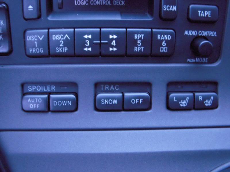
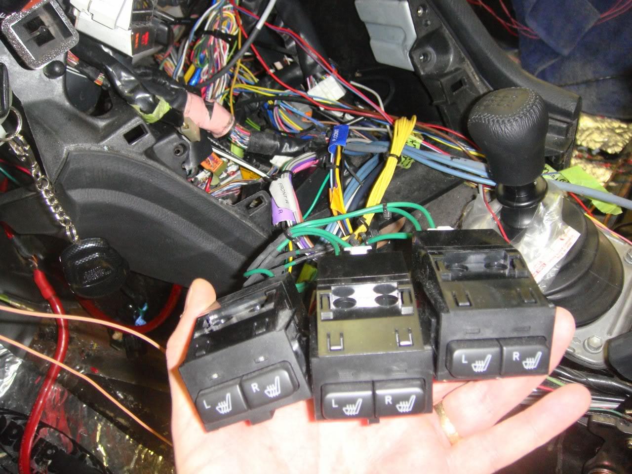
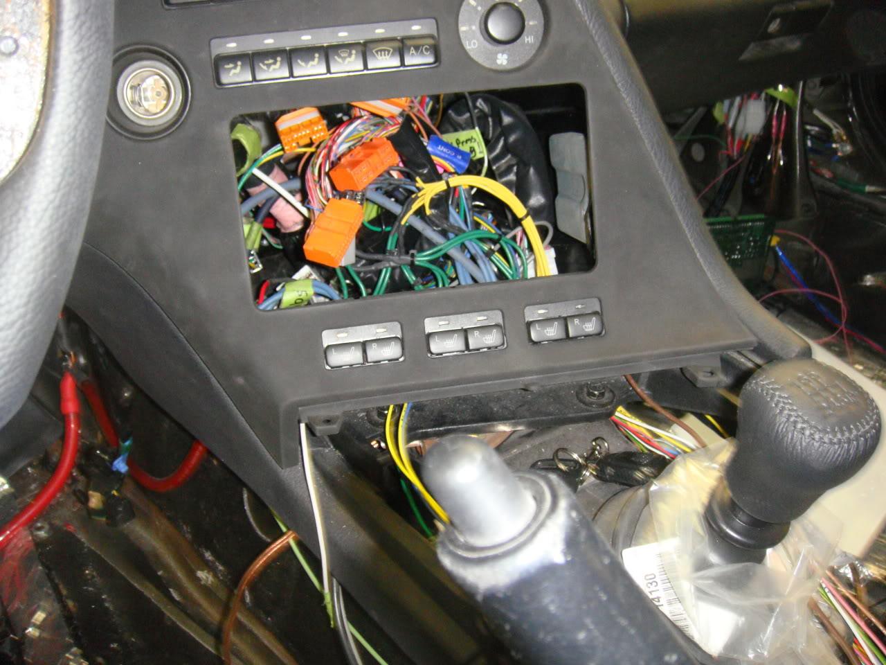
I have lots of toggle switches in my supra to do things like arm the nitrous system, switch on/off the meth system, switch on/off my shift light, etc. I've been mounting these toggle switches in the center console area but have to keep expanding with more and more. So, ever since I saw a picture of the stock seat heater switches (available standard on Canadian supras but you can order them at any Toyota parts department) I've been thinking about using them as my toggle switches because you can get 6 of them across the bottom of the instrument console and the layout looks clean. The picture below shows the seat heater switch module in the right position, but you can actually mount the module with a little adaptation into the left and center positions too. What I really like about these switches is that an LED comes on when the switch is pushed in.
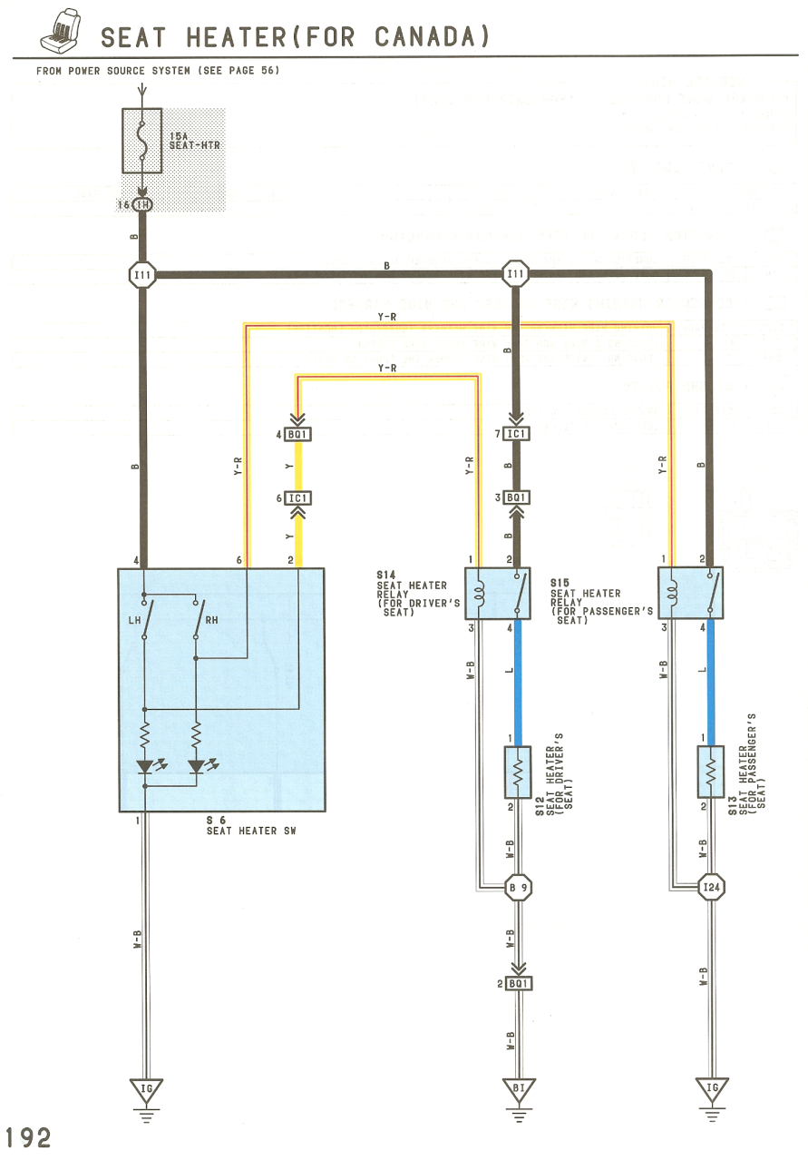
Now, these heater switches can't actually just be used like normal switches. Below is the wiring diagram from the supra manuals. What Toyota does is use a heater switch to control the coil on a relay. So, you need a relay for each heater switch in order to actually do any switching.
When I first thought about how I was going to wire this up I thought we could put some relays and fuses on a breadboard and do it ad-hoc. But, since I am doing this for my show car first (red supra will come later), I thought it would be cleaner to design a printed circuit board. So, I looked online and saw quite a few places that charge reasonable rates to do low quantities of PCBs. Great, now all I have to do is learn how to use one of these site's free schematic entry/PCB layout tools. I chose to go with http://www.4pcb.com . They have a pretty good combined schematic/PCB tool and it wasn't that hard to use. After a couple weeks of going through the tutorials I was off and running.
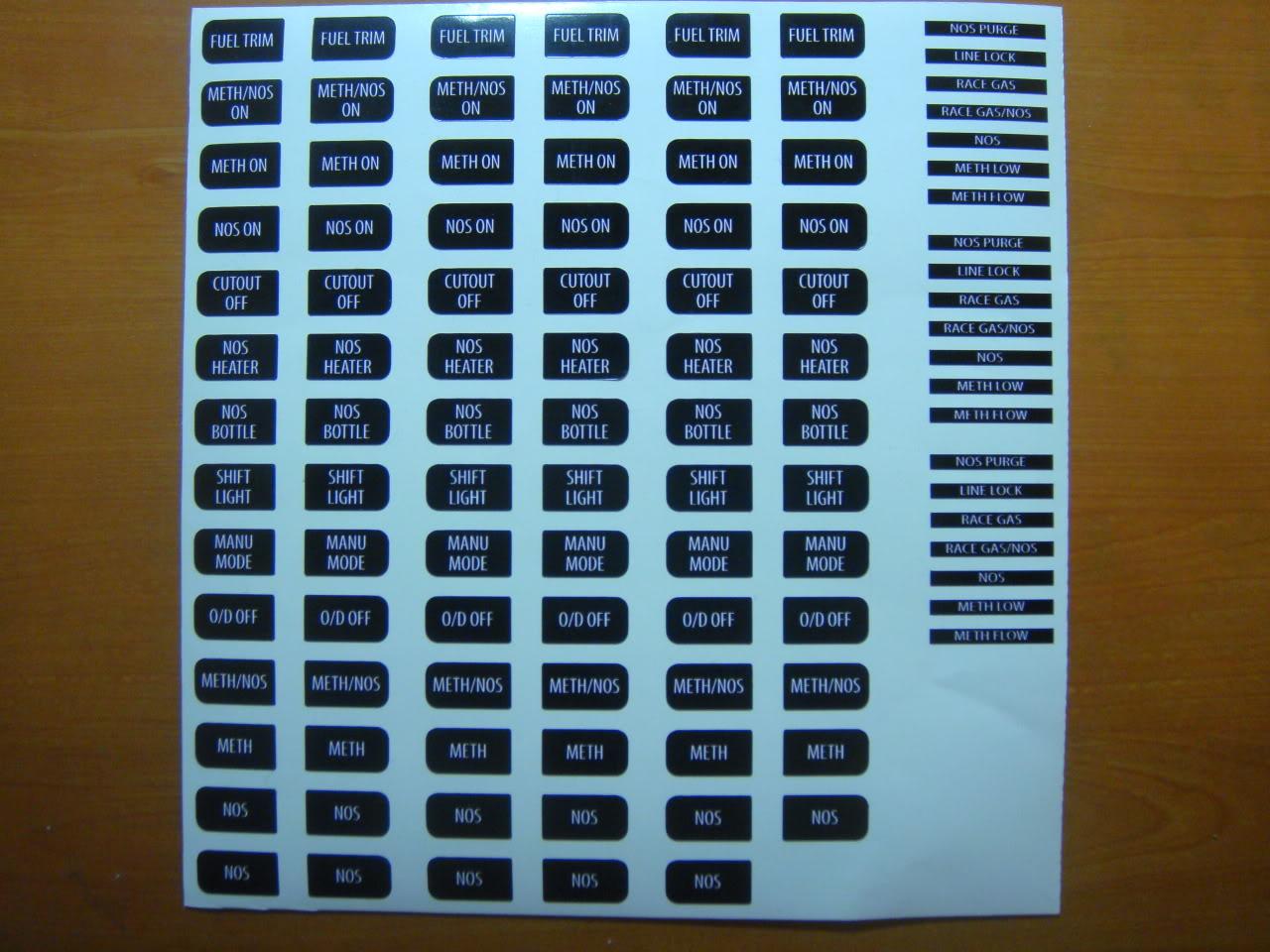
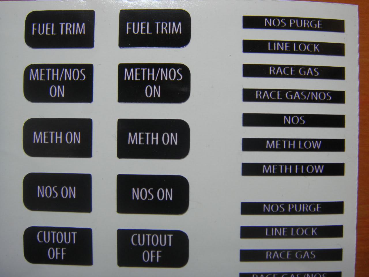
To indicate the function of a given heater switch I needed some labels that will fit a heater button. So, I came up with a list of every conceivable function I could imagine I would want in the future and then went to a sign ship and had them design the labels for me. Below are some views of one cut sheet out of several I had done. Unbelievable as it is, each label is pretty pricey ($2 each) but I wanted something that looked professional and as if it came stock with the car. The smaller rectangular labels I am using for some LEDs that the board I layed out will drive. More about that later.
10-25-2009
The first thing to do for this project was to create schematics in the combined schematic entry/pcb layout tool from www.4pcb.com. I had to create several custom symbols with associated PCB footprints. It took a couple weeks of learning and effort before I completed this step. At the same time I was choosing and ordering the required parts online at Digikey/Jameco and getting any needed data sheets so I had all the dimensioning for the PCB footprints. Creating the footprints was very time consuming and each had to be thoroughly checked over to ensure no screwups in the final boards.
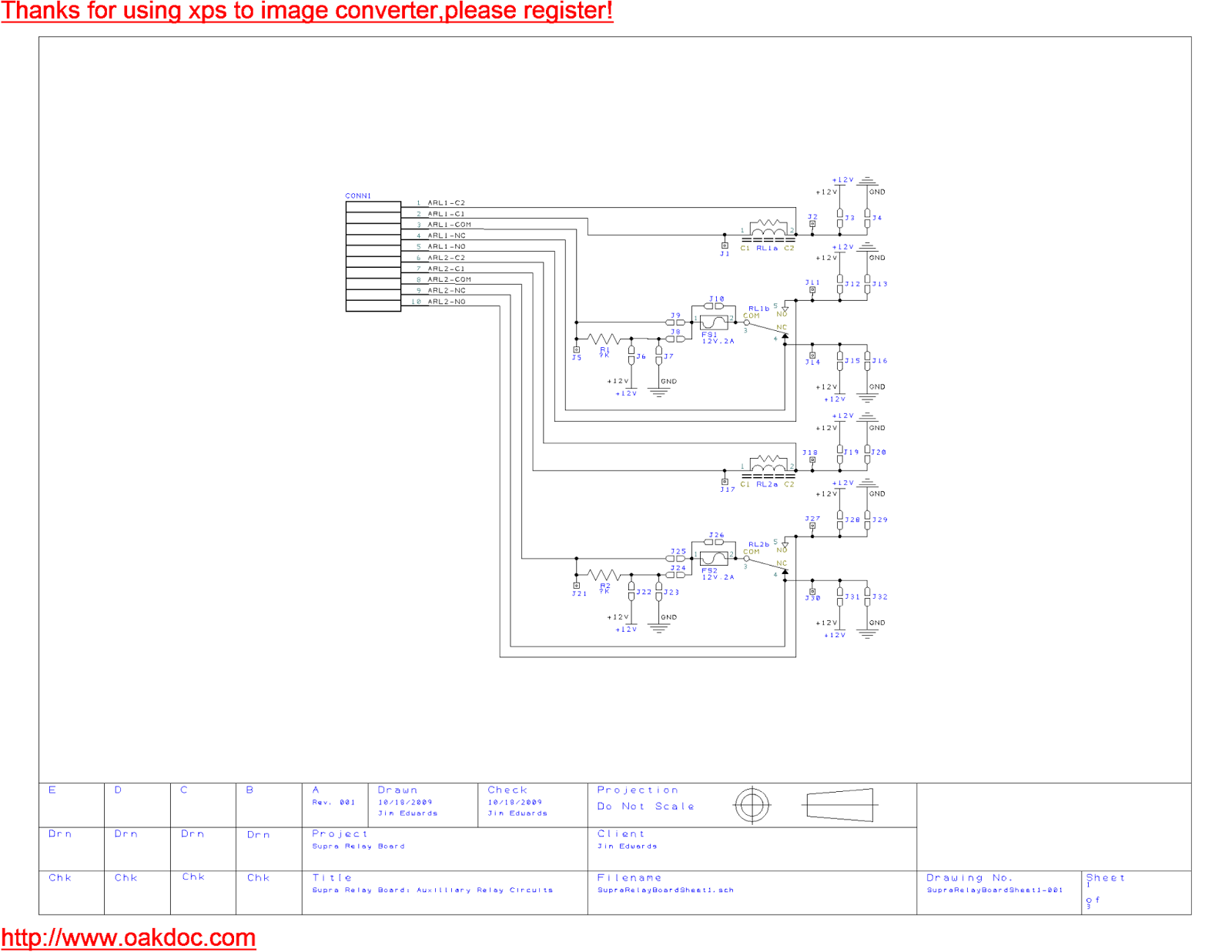
Here's schematic sheet 1 for this project. This is the circuitry for 2 auxilliary relays that can be used very generally. Each relay pin comes out to a pin on a connector with screw in wire terminals. I plan to use at least one of these relays as part of an overall circuit that switches the stock horn between horn use and use as the switch for a linelock.
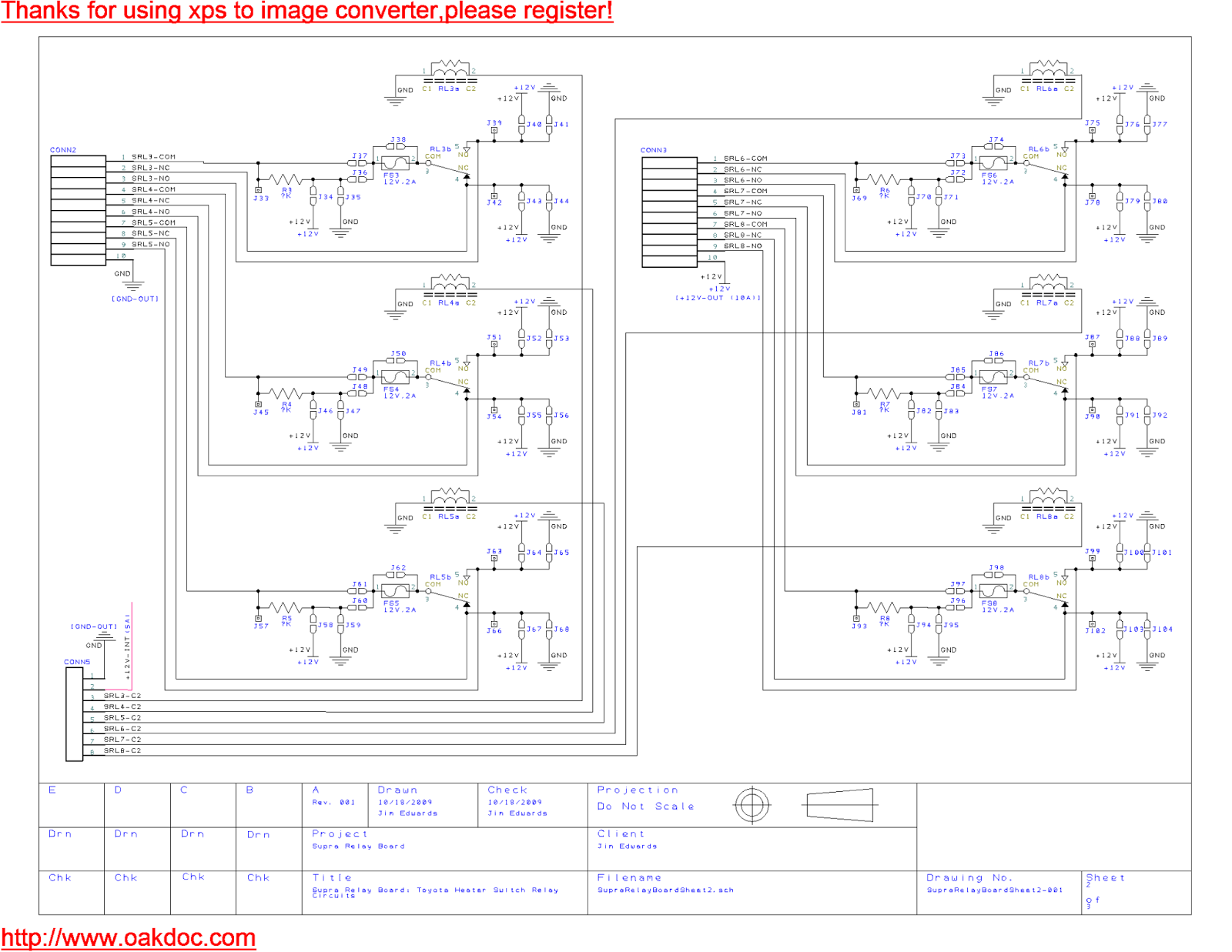
Schematic sheet 2. This sheet shows the relays controlled by the stock heater switches. I've set it up so that each of the relay pins can be strapped to ground or +12V via solderable pad bridges, and in addition for the relay common it is possible to have a pullup resistor or series resister depending on the strapping. The coil for each relay is hooked to a heater switch, so that when the associated heater switch is pushed in the relay will change from the NC position to the NO position. I plan to use some of these relays as ground switched inputs to the AEM for various purposes such as enabling the shift light, etc. Other relays will be used for other things like turning my nitrous heater on, etc. Actually since these relays are low current, the nitrous heater one would actually be turning on a higher current relay located close to the heater.
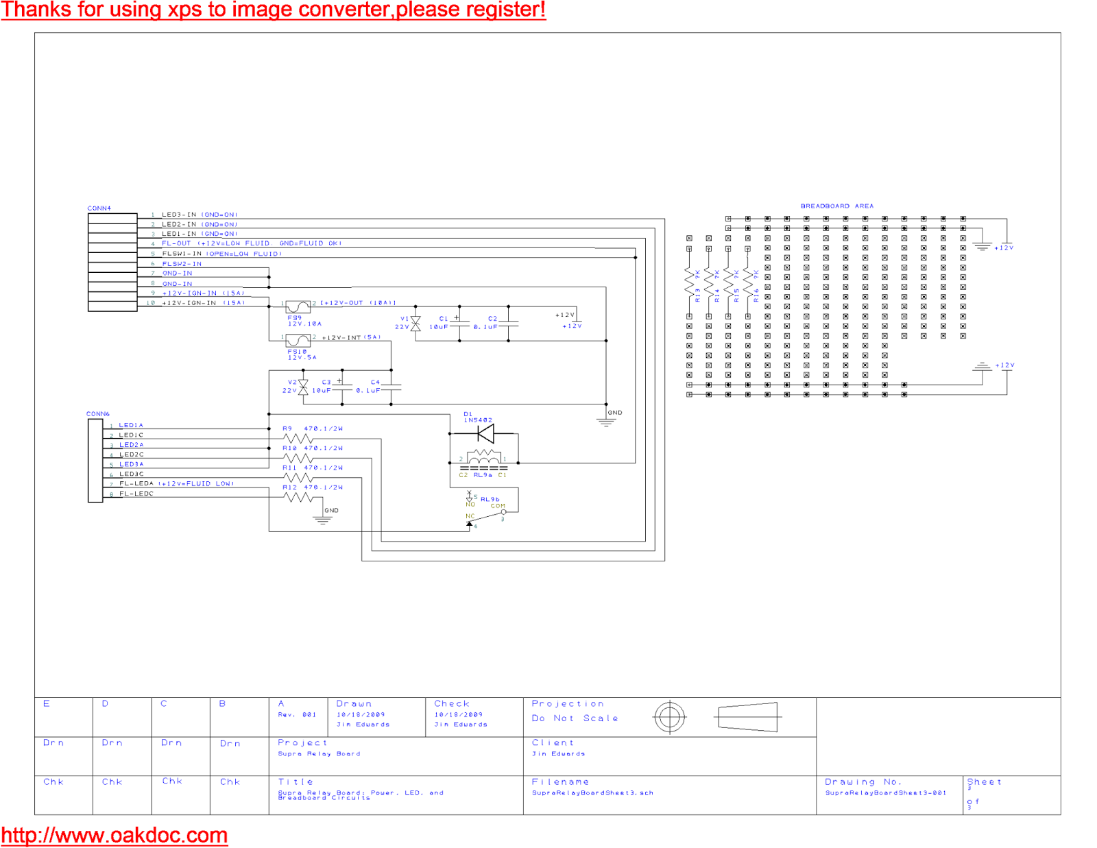
Schematic sheet 3. This sheet shows the power and ground entry to the board, the LED circuitry, and a breadboard area. Good thing I included a breadboard areas because I've already had to use it when I discovered I needed a +5V power source in order to use one heater switch to enable/disable my racelogic traction control system. In that case I needed to wire up an LM7805 +5V regulator to convert +12V down to +5V, and then I ran a wire to a jumper pad on the NO terminal of a heater switch relay. One of the LEDs (LED4) can be used with a fluid sensor reed relay switch that is open when the fluid is low. I plan to use it to indicate when my methanol tank is low on meth and I have it coming back out as an input to the AEM that will disable meth operation if the tank is low. The other LEDs can be driven by AEM outputs for whatever purpose. Since I have a separate AEM config file for pump gas (+methanol injection) and race gas (+nitrous) I will use one LED as an output from the AEM to indicate when I'm set up for race gas. That way I hope I never mistakenly put pump gas in the car when the AEM is configured for race gas.
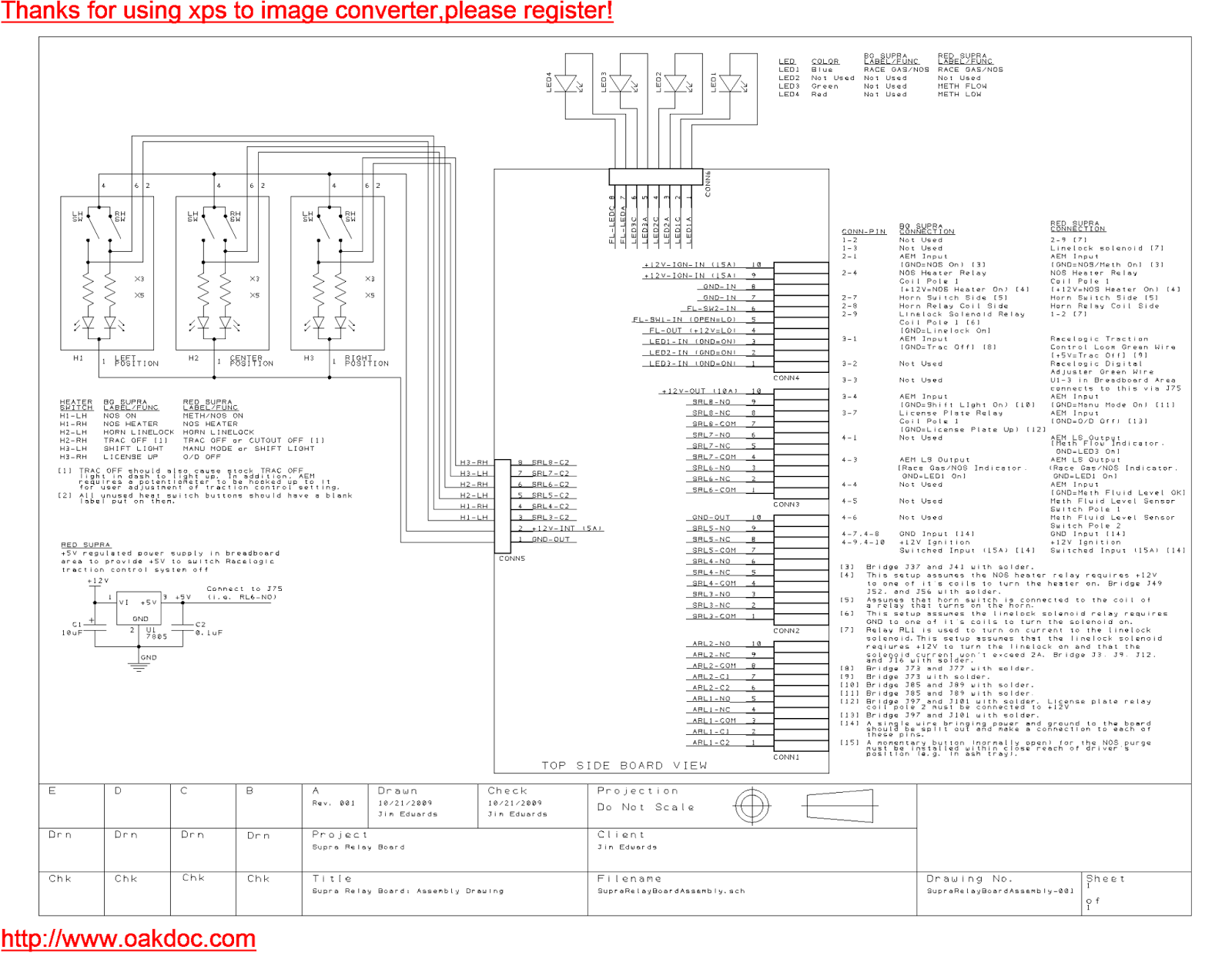
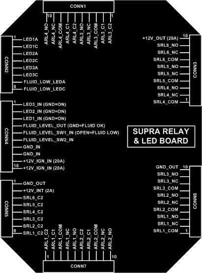
Here's the assembly drawing showing how I plan to hook all this up to the heater switches, LEDs, and various I/O with the AEM and other systems in the car. I will use this same board in 2 different supras so the assembly shows how each is going to be setup.
10-31-2009
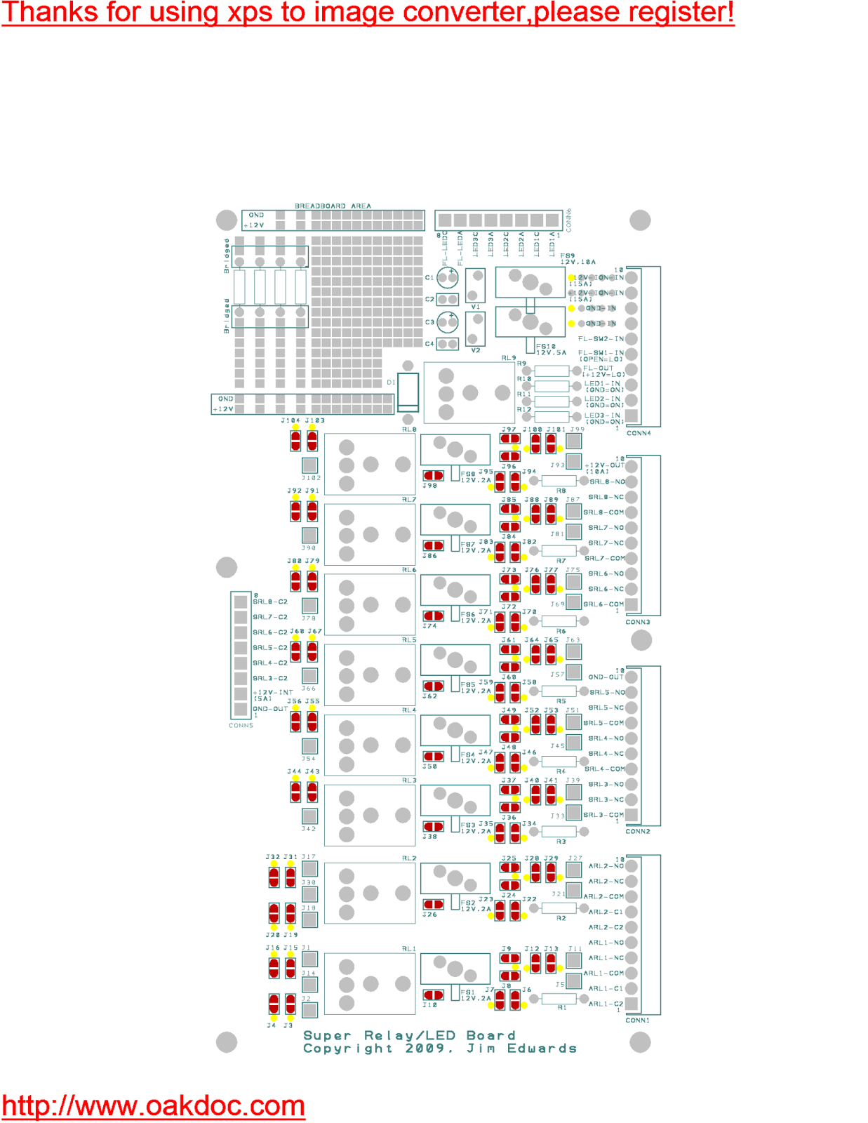
Below are pics of the the circuit board I layed out. By the stats in the 4pcb tool it took over 32 hours of time to create the schematics and lay out the PCB. I pretty much routed this all by hand, although sometimes I would autoroute a single net and work from there.
Top silkscreen/soldermask:
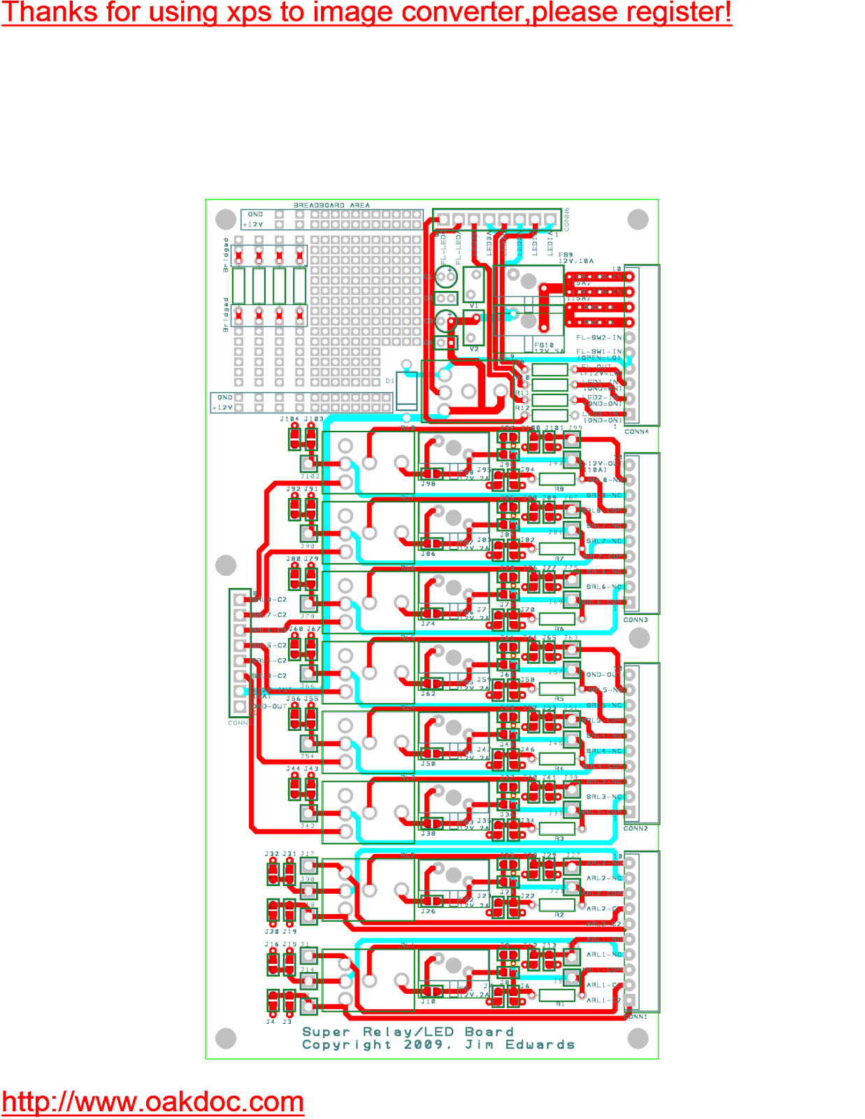
All layers turned on:
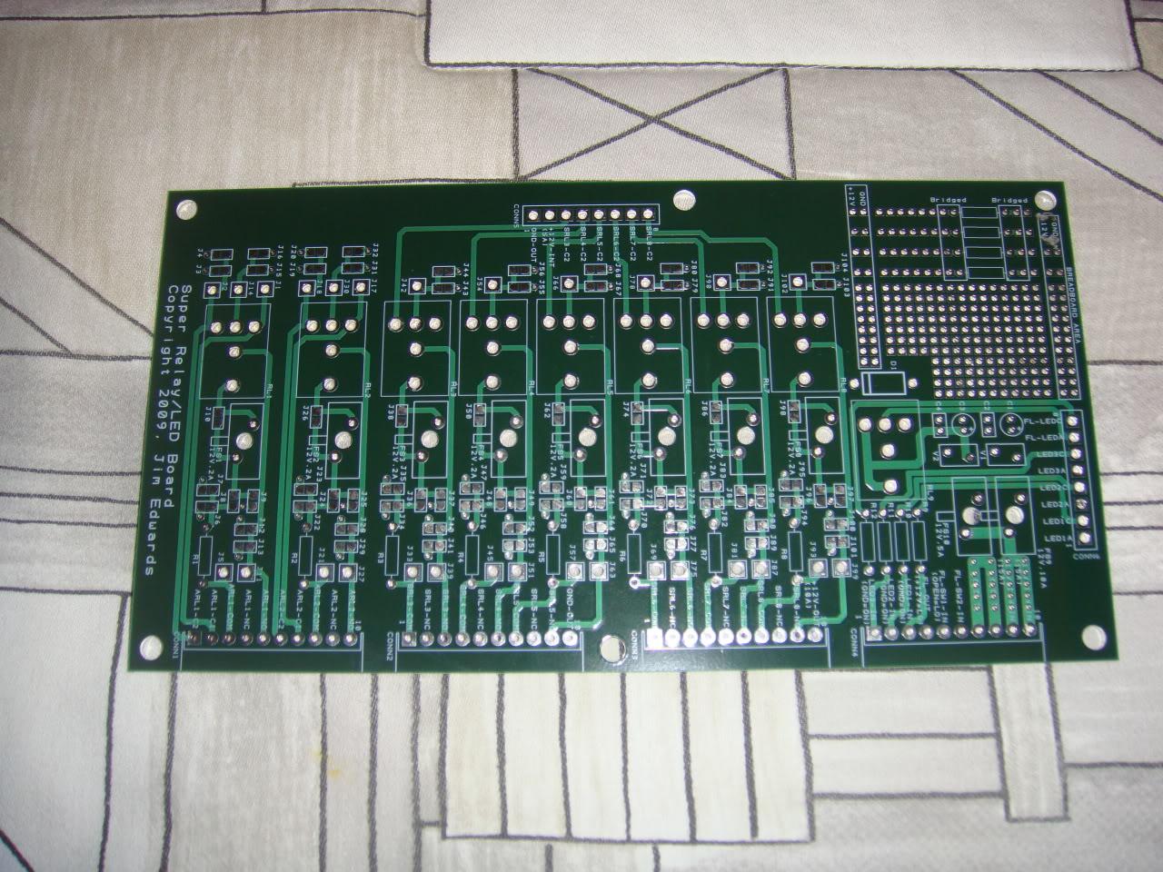
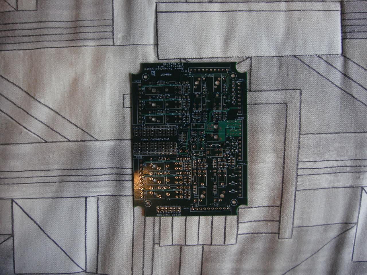
And here is the final bare board back from fabrication by www.4pcb.com . It was turned around in 4 days.
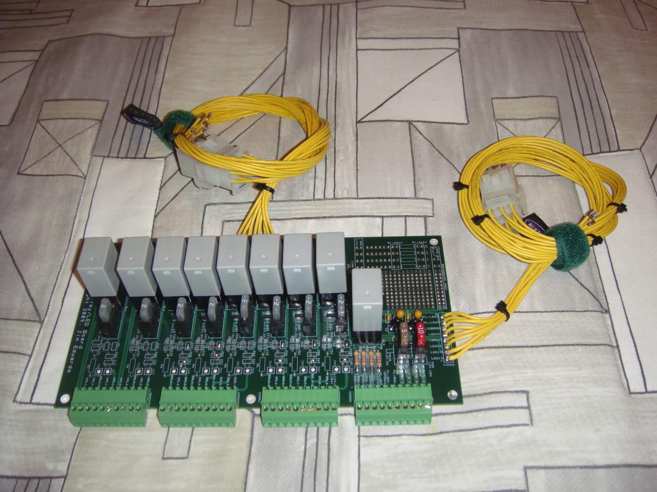
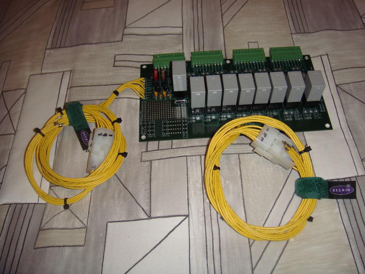
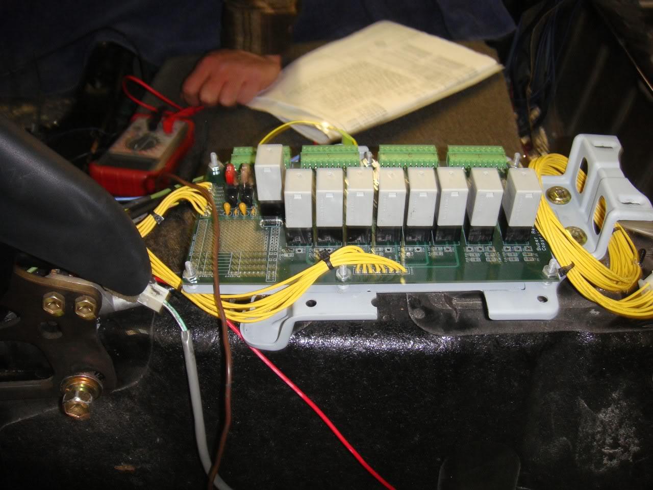
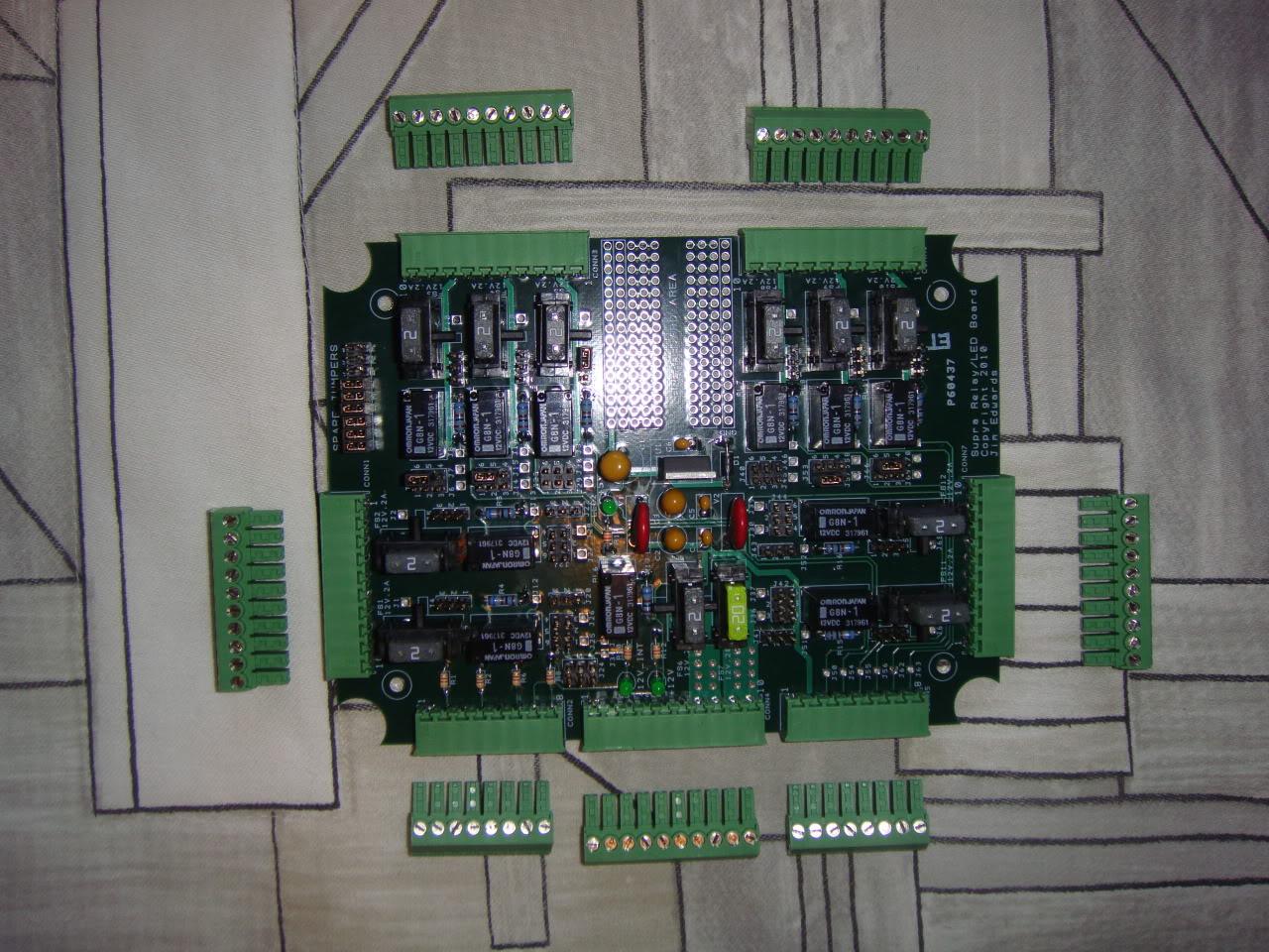
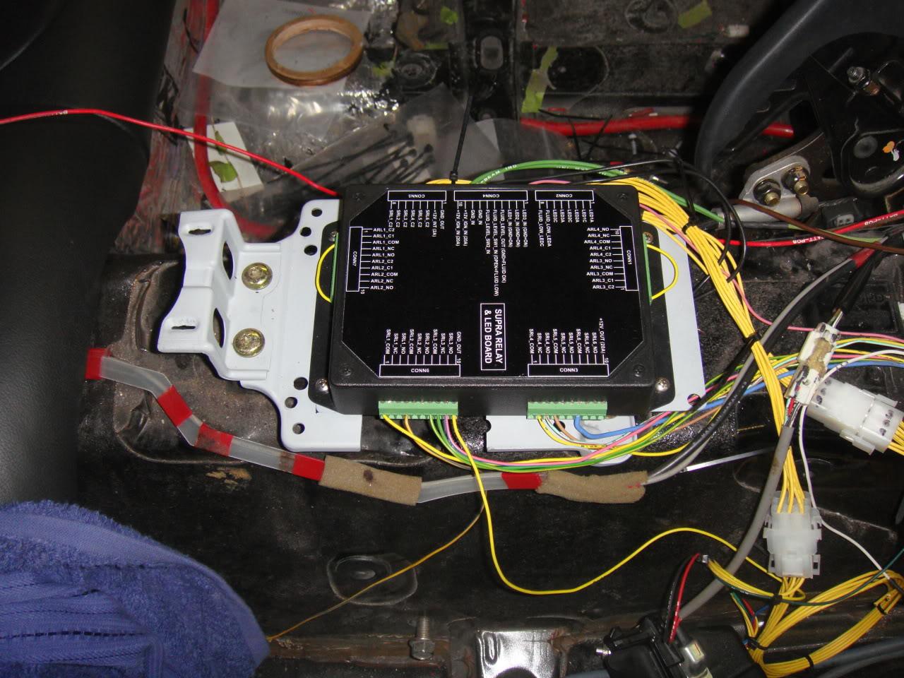
Here's the circuit board after installing all parts and wiring up a couple harnesses. The green connectors can pull apart, making it easy to keep all the wiring connections in the car intact whenever I have to remove the board to change some of the strapping options.
11-1-2009
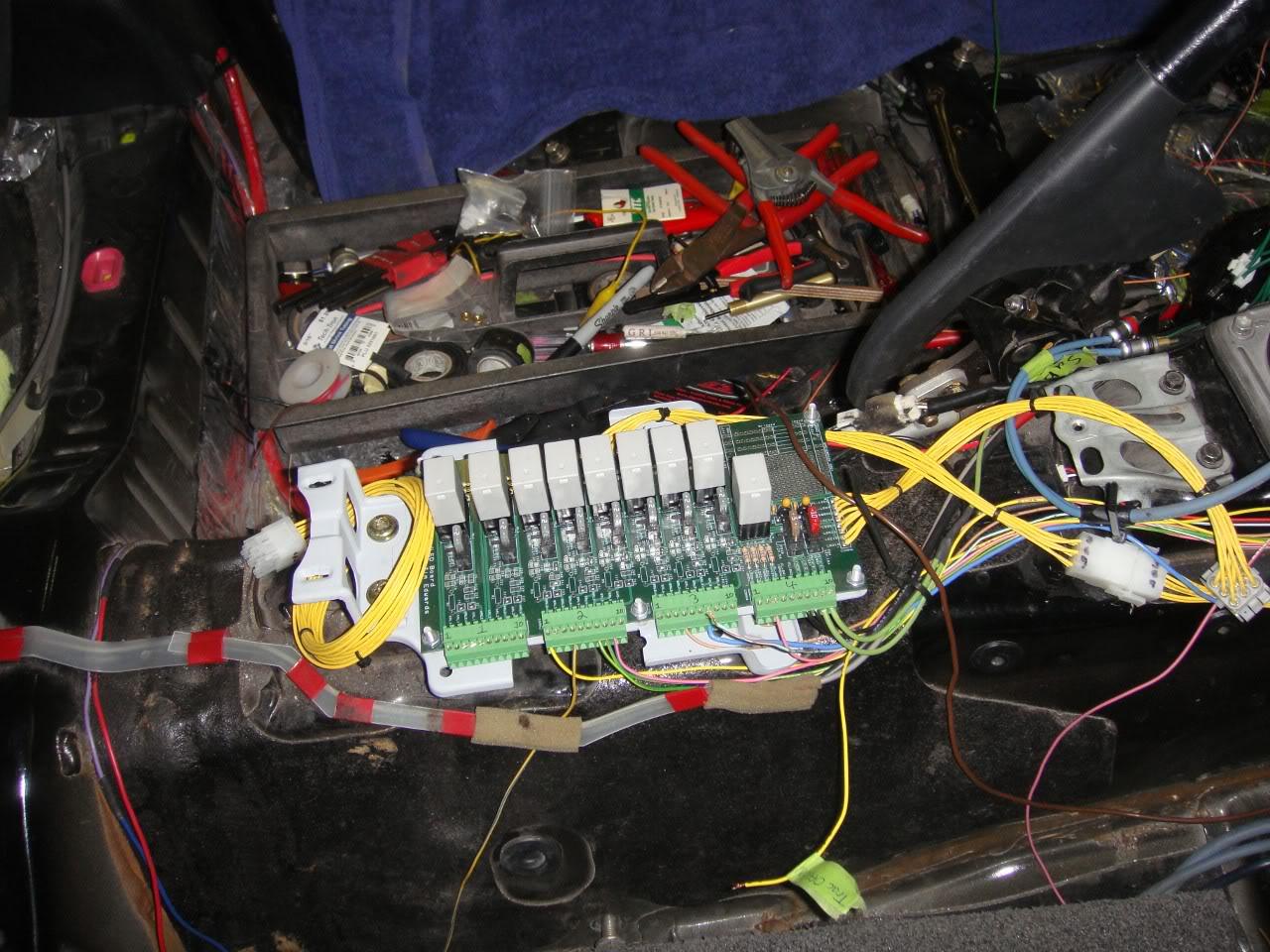
Around 4.5"W x 8"L and about 1.5" tall. All dimensions should fit comfortably under the center console. I could have made it much smaller in width but I wanted all the solderable jumper pads to be on the top side where they could conceivably be accessed for soldering without having to pull the board out after installation. In retrospect I think I should have put them all on the backside and cut off 1.5" or so in width. Also, I wished I had put in fuseholders just to hold spares and I should have used the green connectors for the two wire to board harnesses, which take hours and hours to fabricate because each pin must be carefully crimped, tested, and inserted into the Molex MLX housings/receptacles. I actually was using a much smaller series of Molex housings/receptables (Micro-fit series, about 4 times smaller than the MLX series) but the pins are so small that making reliable crimps is just about impossible for a human.
11-2-2009
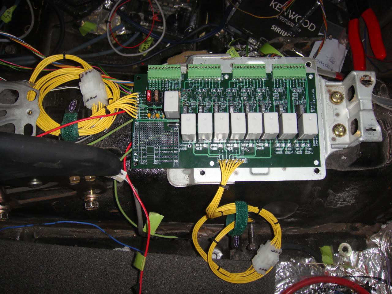
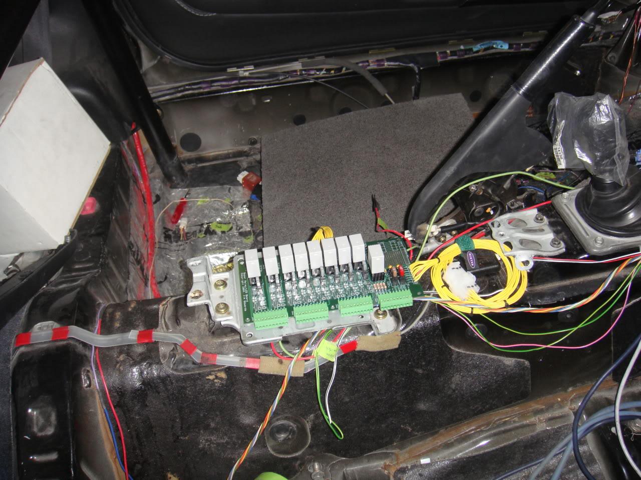
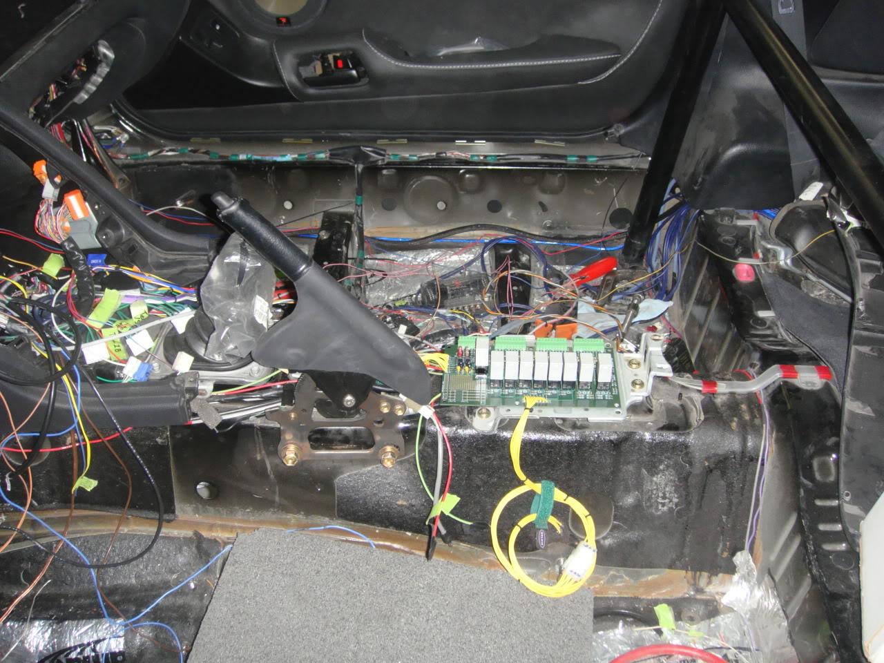
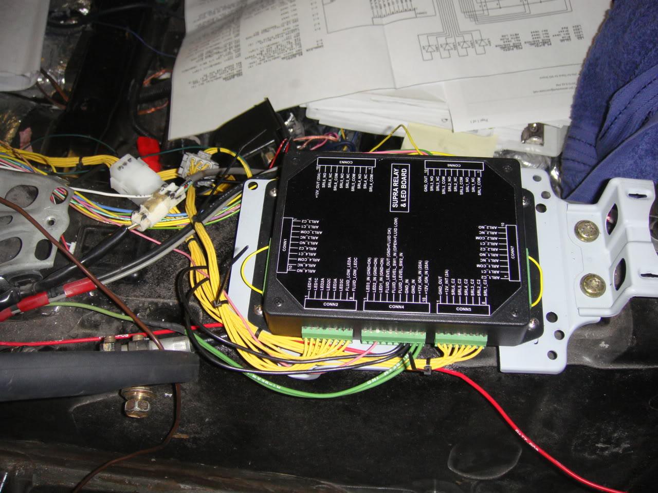
Here's the board sitting in the location it will be installed at. I believe this is where the airbag ECU normally sits. There's plenty of clearance around it and with respect to the center console housing above it.
2-15-2010
We're finally getting around to hooking the relay board up to the toyoto heater switches and the various points of control in the car. We've used all 6 switches up with the following functions:
1. Nitrous system on/off
2. Nitrous heater on/off
3. Linelock horn switch on/off (i.e. use horn for linelock control when ON)
4. Traction control on/off
5. Shift light on/off
6. License plate up on/off
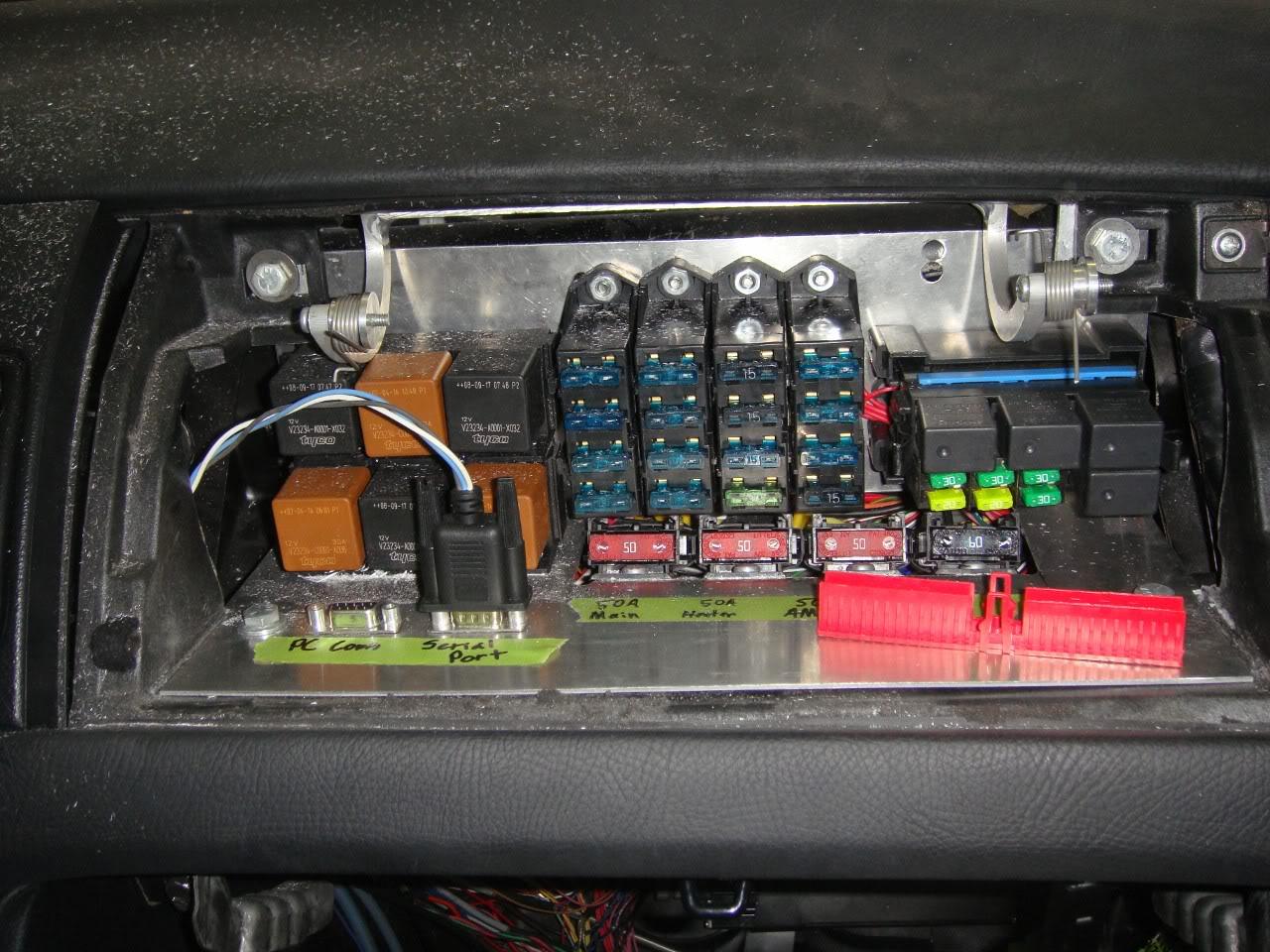
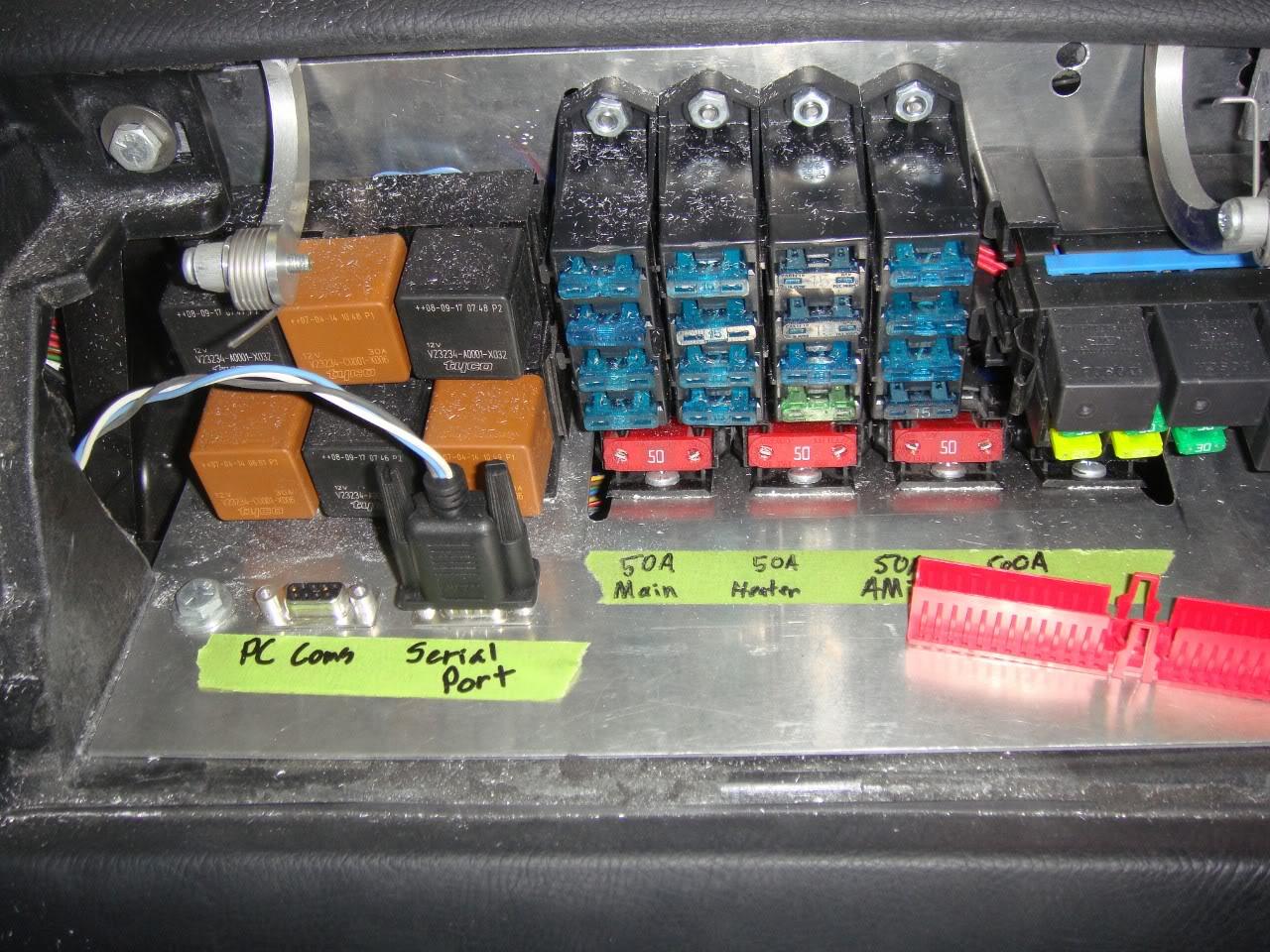
Not related to this relay board, but still pretty cool is the relocation of the engine bay fuses to the passenger airbag area. The cover will pop up when you give it light push in. The 2 serial port connectors on the right allow hooking up of a laptop to the AEM and the other one goes to the AEM serial guage.
3-27-2010
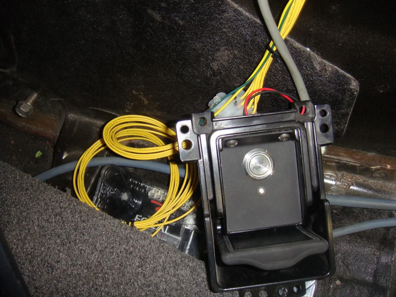
The relay board also drives up to 3 general purpose LEDs, each of which can be turned on by, for example, a low side switched output from the AEM. In this car I am only using one LED shown below mounted in the ash tray and which indicates when the AEM is loaded up with the race gas/nitrous map. Basically just a safety light so I don't do something stupid like put pump gas in the car. Also, you see a nifty nitrous purge billet momentary button I found online (actually you can get any custom lettering you want on these billet buttons). When the car is powered up, the small ring around the purge button lights in blue.
3-28-2010
Thanks. Well, I actually finished designing a 2nd rev of the board recently. It's more accurate to say it is a complete redesign. It is 30% smaller in area, has 2 additional general purpose relays (for a total of 11 relays on board), has an onboard 5V voltage regulator for use in the breadboard area, and is much easier to configure via jumpers, rather than bridging pads with solder. It also fits into a very nice plastic enclosure I found at www.polycase.com . I found a really nifty automotive grade, 25A ultraminature relay that made it possible to squeeze more into less board area. These relays are less than half the size of the standard ISO micro relay, which in turn is about half the size of a normal bosch relay. Imagine getting nearly the same 30A capacity of a bosch relay in a package that is 1/4 the size!
3-30-2010
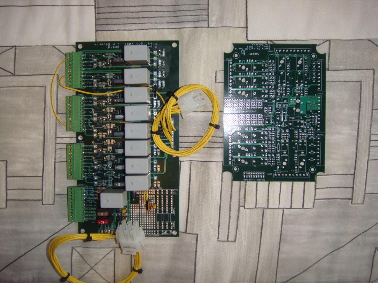
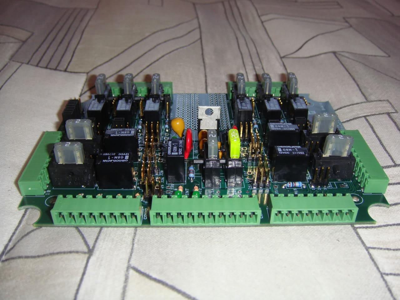
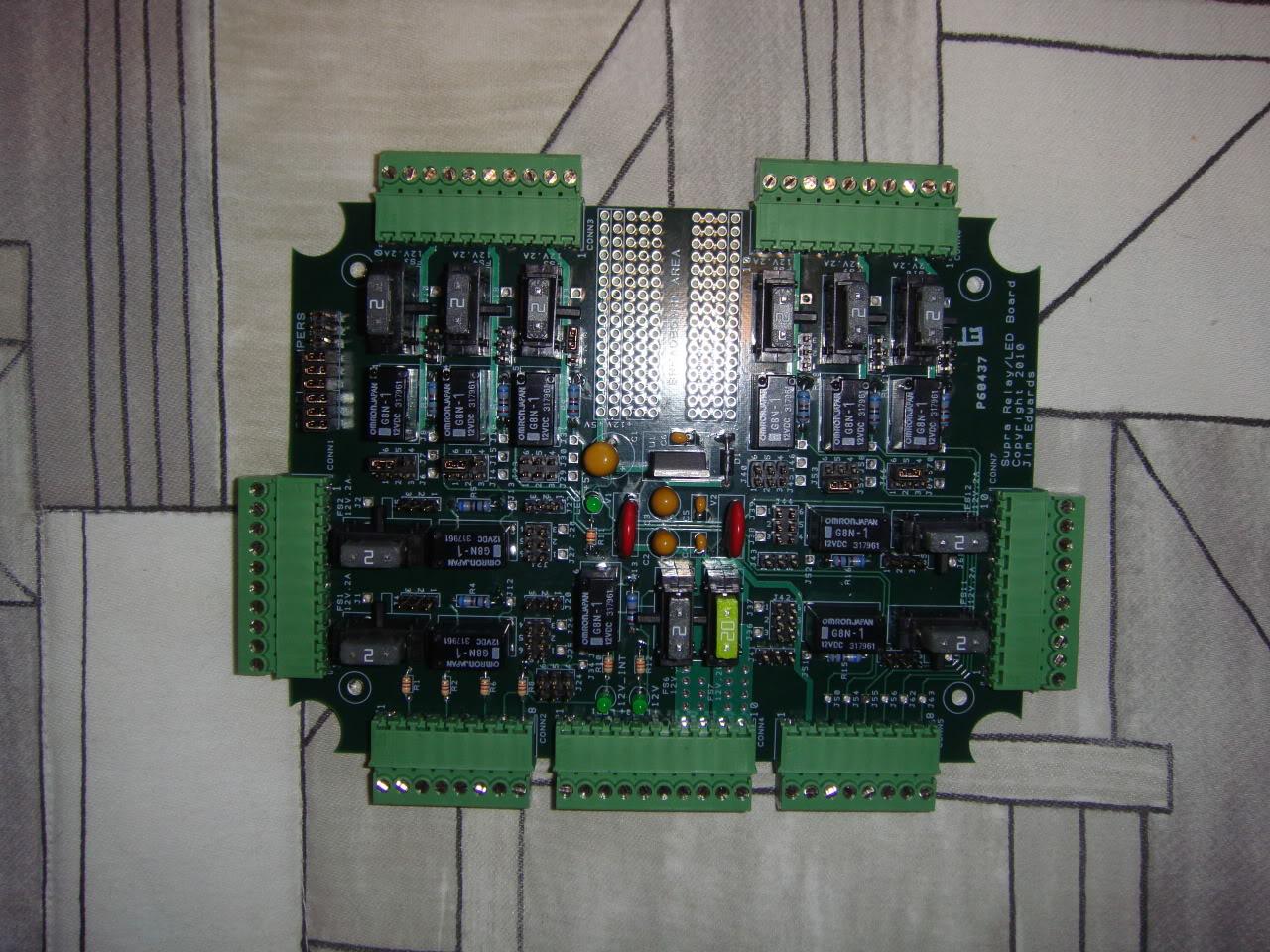
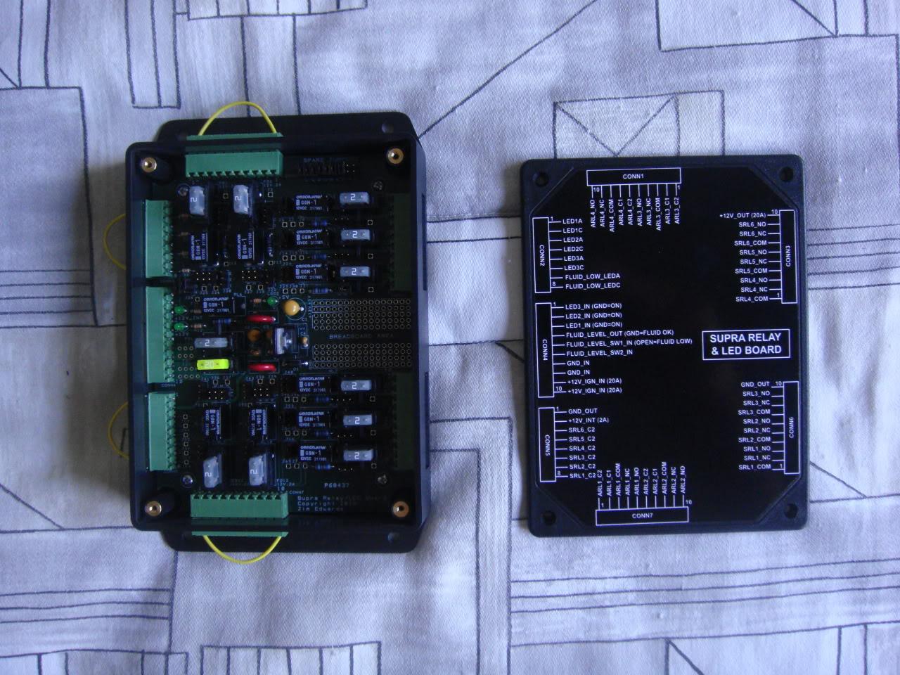
Here's the new, smaller version 2 relay board:
And here it is beside the bigger version 1 relay board:
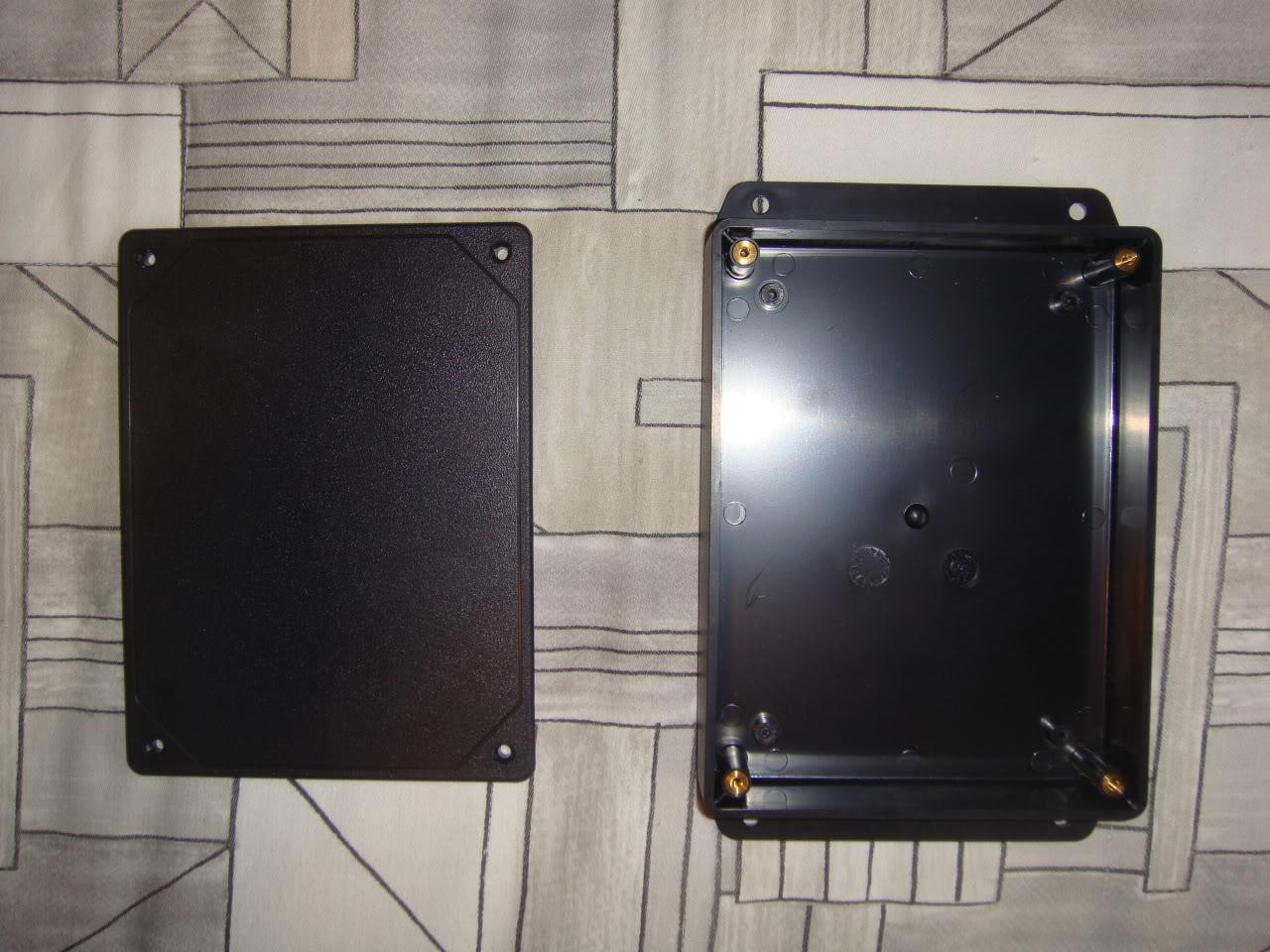
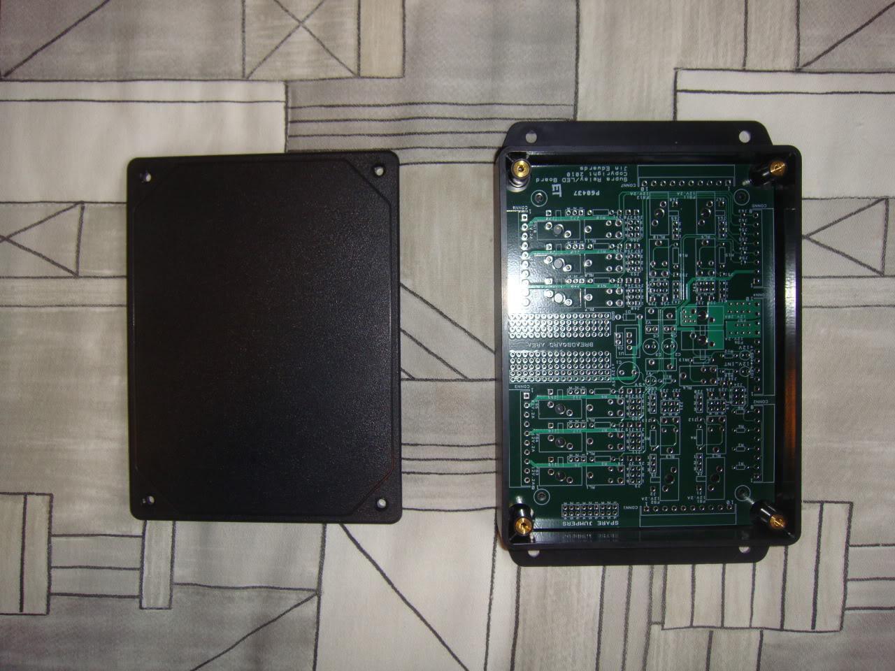
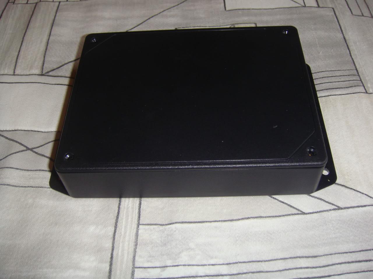
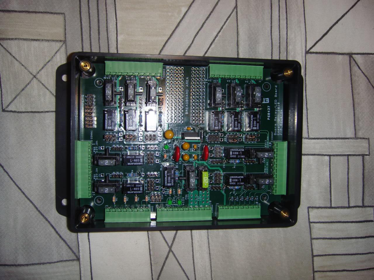
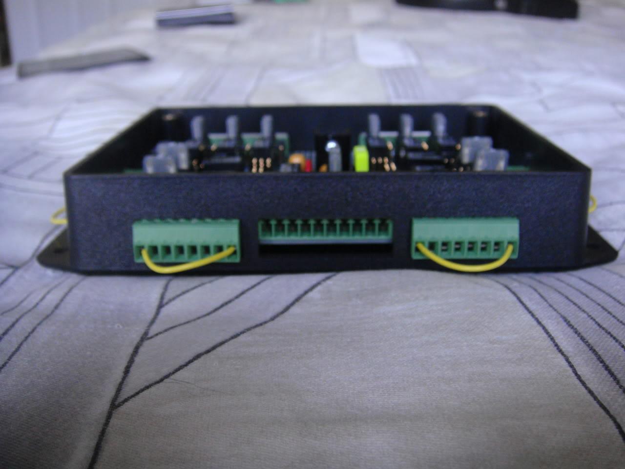
The version 2 relay board will be mounted inside this flanged case with removeable cover:
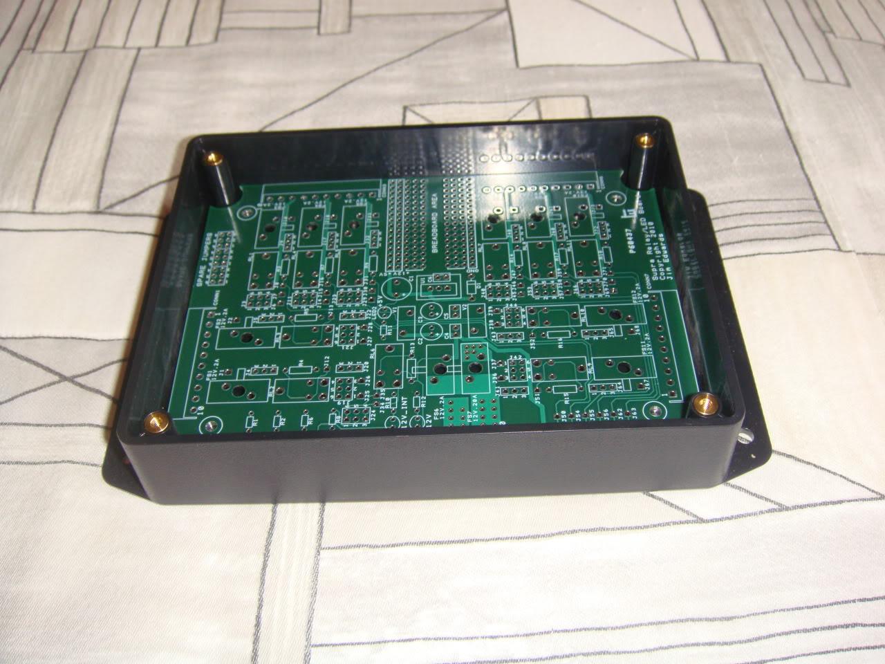
Here's the board sitting in the case:
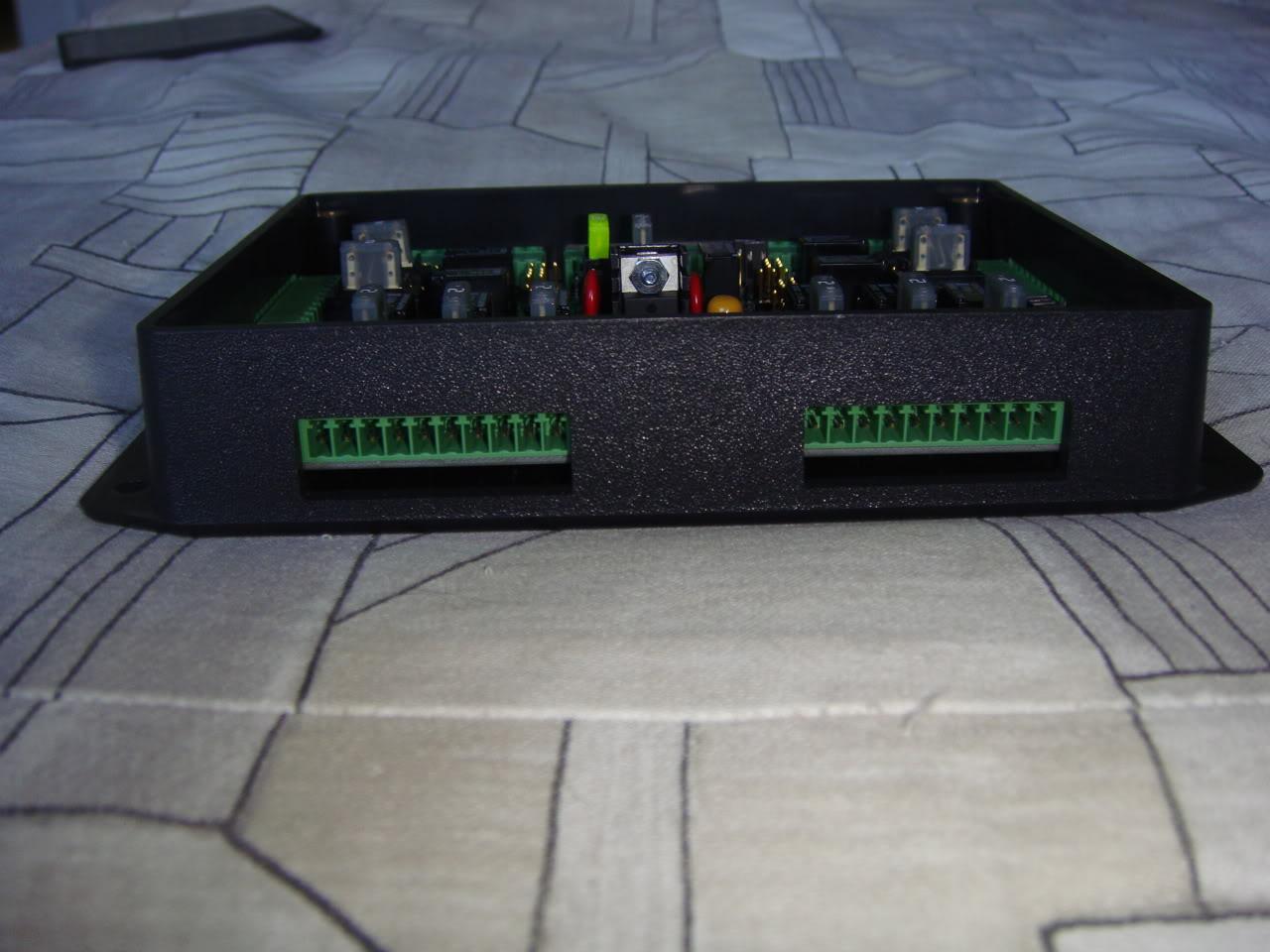
And the case all sealed up:
4-3-2010
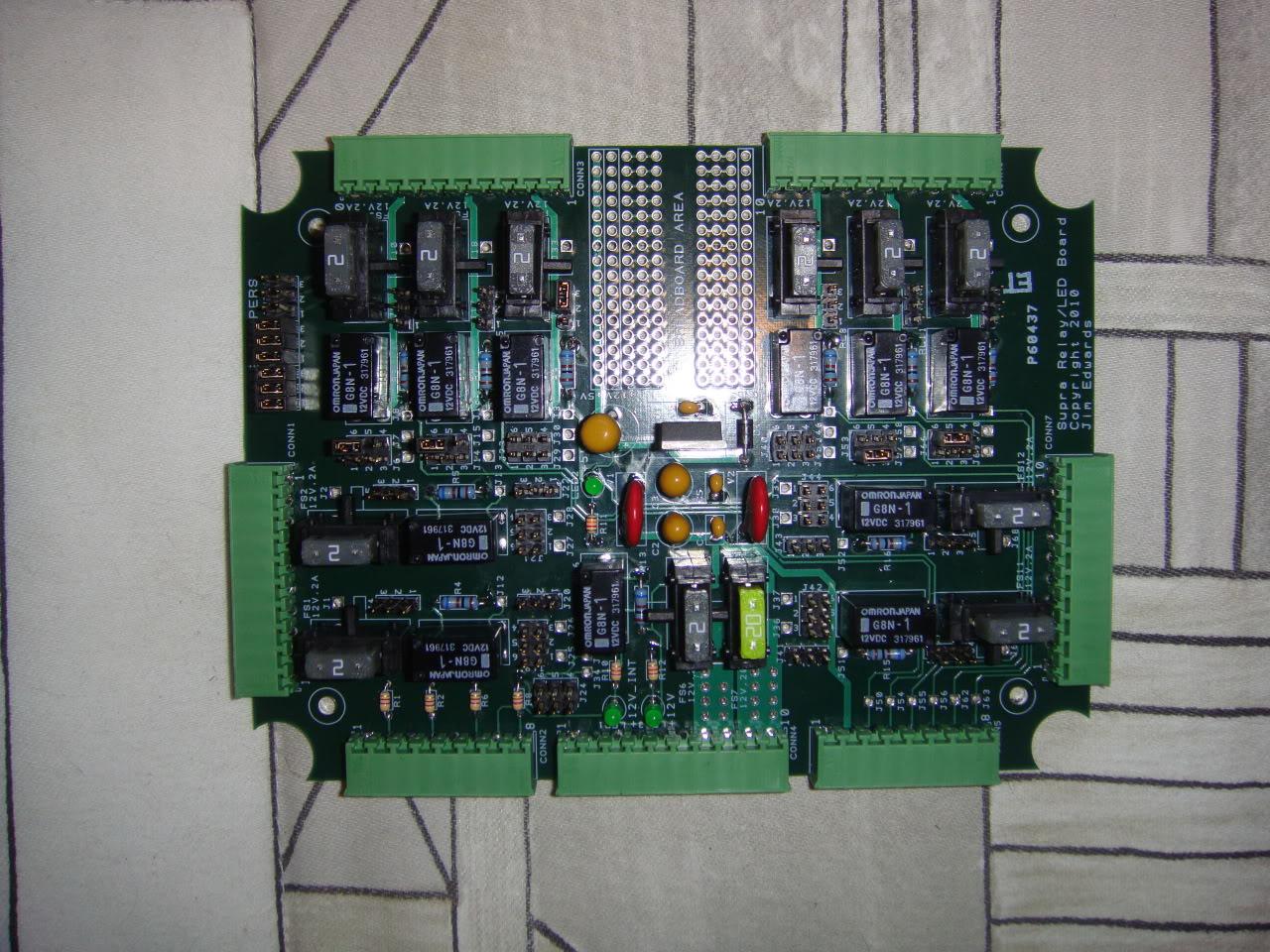
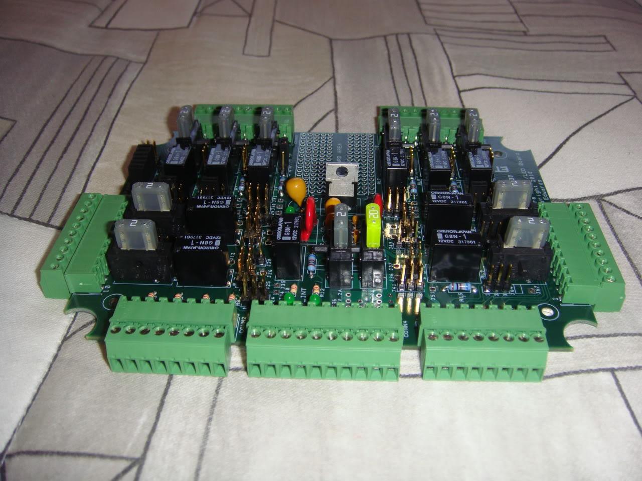
I got ambitious this weekend and soldered all the parts on the new version of the relay board. This thing is so much more compact than the older version of the relay board and it only took me 5 minutes to configure it with the jumpers (old board took about an hour of soldering). Here it is, again note that these ultraminature relays are rated to 25 amps!:
Here are the female connectors with screw type terminals. Install your wires in them and plug into the mating male connectors on the board. If you need to pull the board out of the car, it's easy to disconnect these terminals so the wiring all stays in place.
And here's the board in the case:
4-12-2010
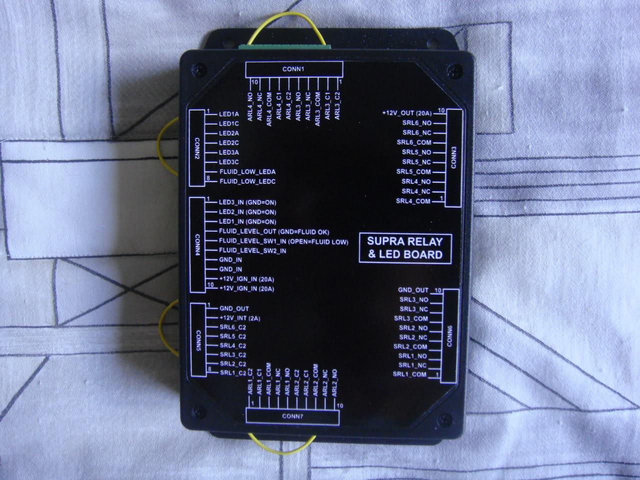
I submitted a job to Polycase to CNC machine the cases for the cutouts needed for the connectors and that should be ready in early May. Meanwhile, I did the graphics design for some black vinyl stickers I will put on the case lid as shown below:
4-18-2010
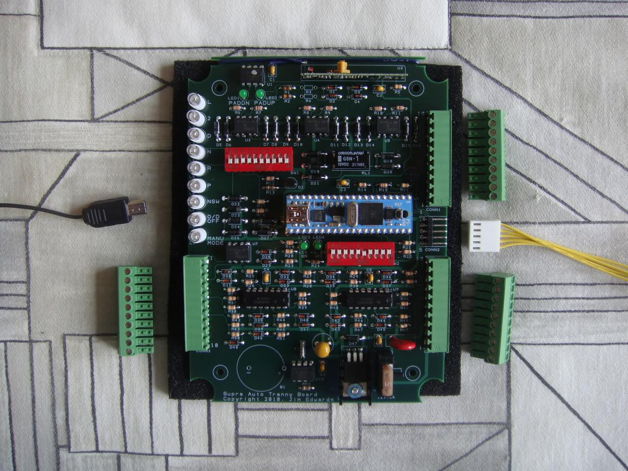
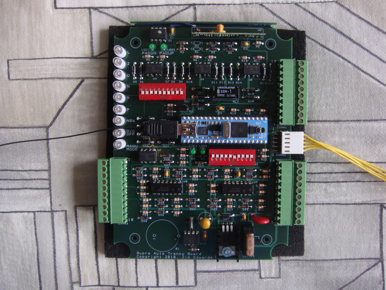
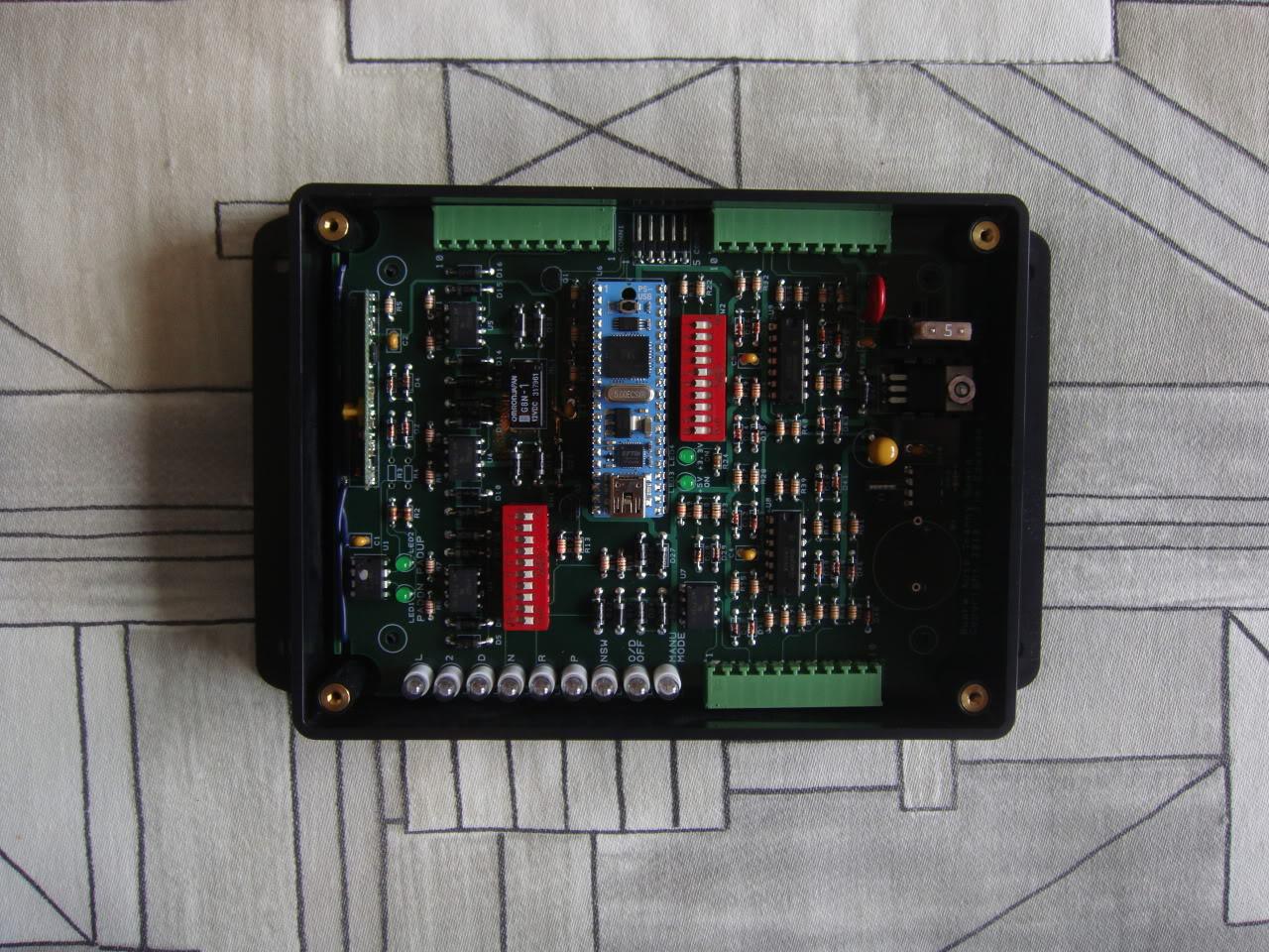
My new project is a circuit board to provide a complete seamless interface between my 4L80E transmission and any ECU that is set up to the control the stock A340E transmission. It will take care of properly driving the gear selector lights in the dash (and to the ECU) and the manu mode, O/D off switches, plus a few other goodes like driving an OLED display that shows actual forward gear, lockup status and an RF wireless paddle shifter. With this interface board it will finally be possible to run my 4L80E transmission in full auto mode or full manual mode at any time. It uses a pretty cool embedded processor called the "propeller" that has eight 32-bit processing cores each with it's own local memory plus access to a global shared memory. In addition it has 32 I/O lines. This processor rocks.
4-24-2010
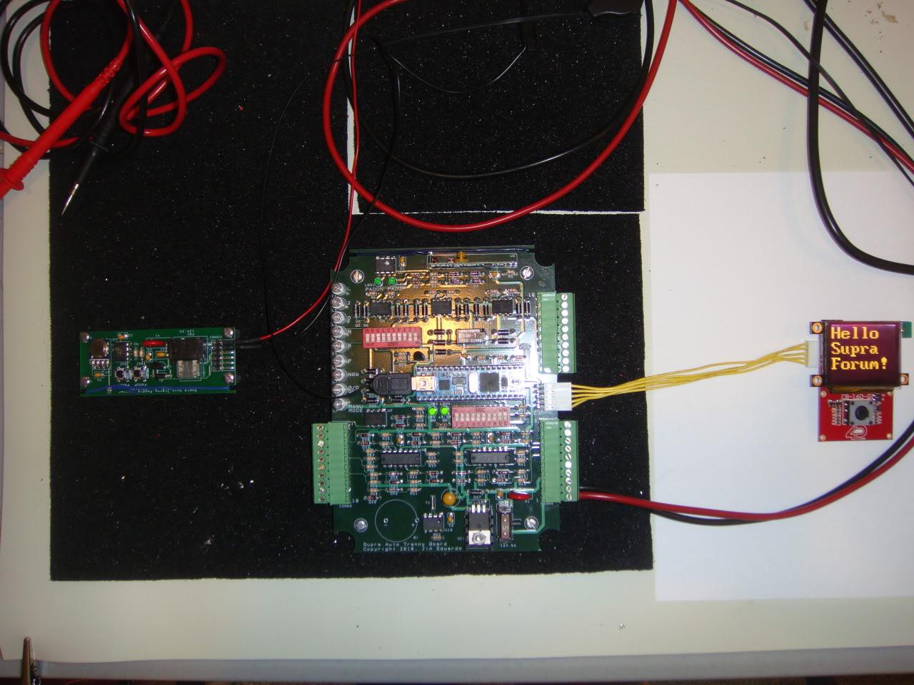
The auto tranny CPU board is alive! On the right is the 160 x 128 resolution, 1.7" OLED display. On the left is the paddle shifter board that communicates wirelessly to the CPU board in the center when paddle up/down switches are opened/closed. Works like a champ.
5-6-2010
Cases finally came back with custom CNC machined cutouts for connectors. Here's the board and box, ready to swap out for the version 1 relay board in the BG supra. Only took me around 3 or 4 months to turn this all around. Can't believe it's finally done.
5-29-2010
The 2nd version of the relay board with the new case is now mounted and hooked up in the car. Everything seems to work fine on the switches.
Great detail ?
Posted by Diggymart on 1/7/20 @ 5:24:14 AM