You must be logged in to rate content!
13 minute(s) of a 341 minute read
9-11-2009
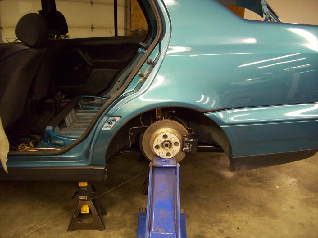
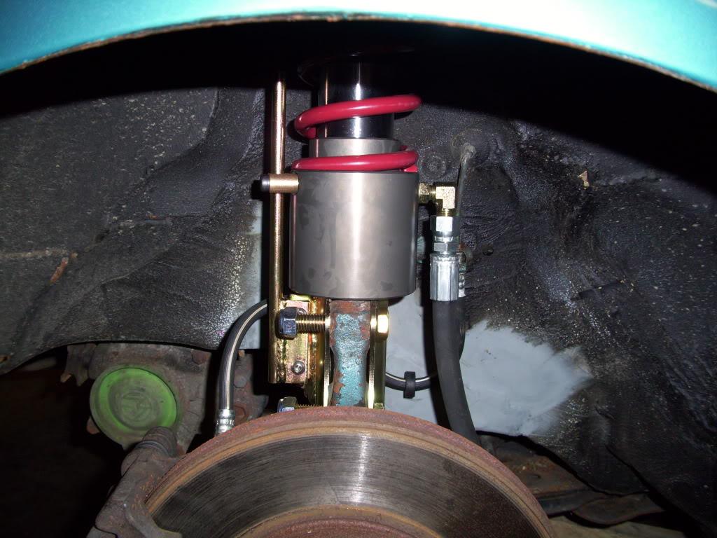
Got the struts assembled and installed into the car.
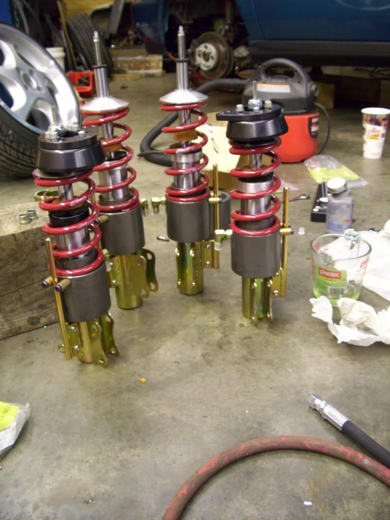
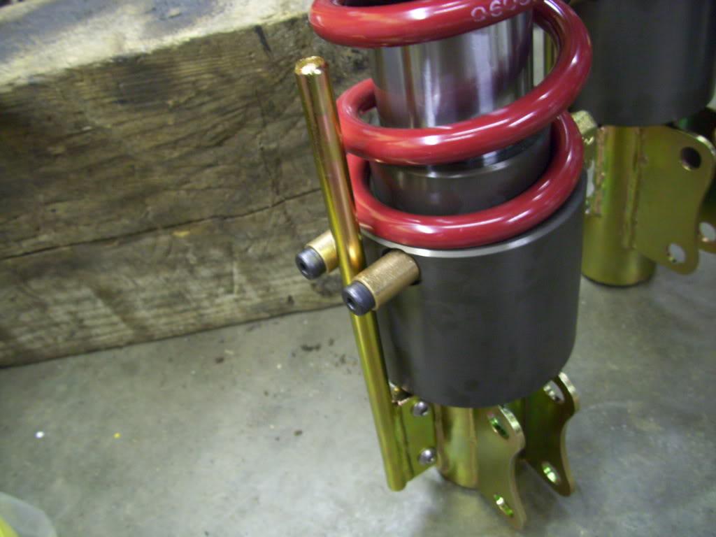
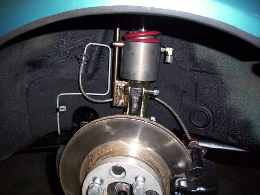
These pins are just to prevent the piston from rotating on the housing so the fitting doesn't hit the tire. Not the most elegant solution, but it was the best I could come up with at the price I wanted.
Ground control uppers all mounted up.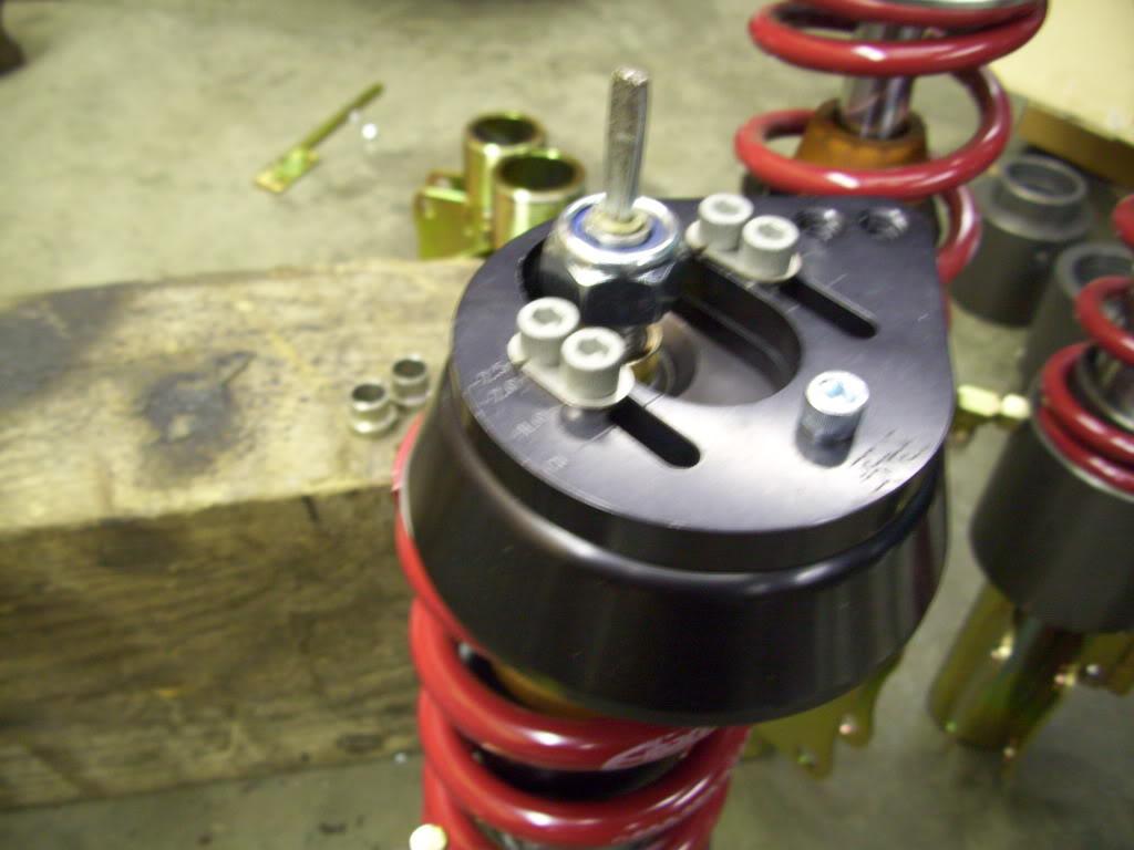
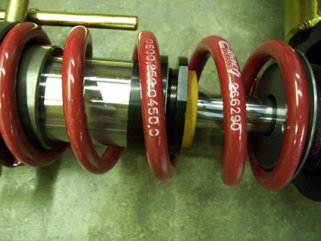
Rear bumpstops.
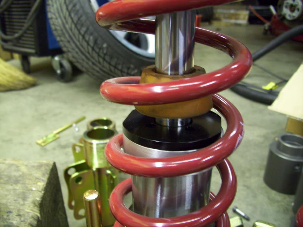
I had a wee little bumpstop in the fronts, which I ended up cutting out later, but might reinstall at some point.
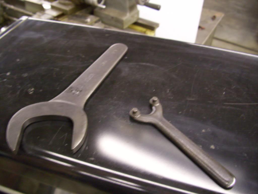
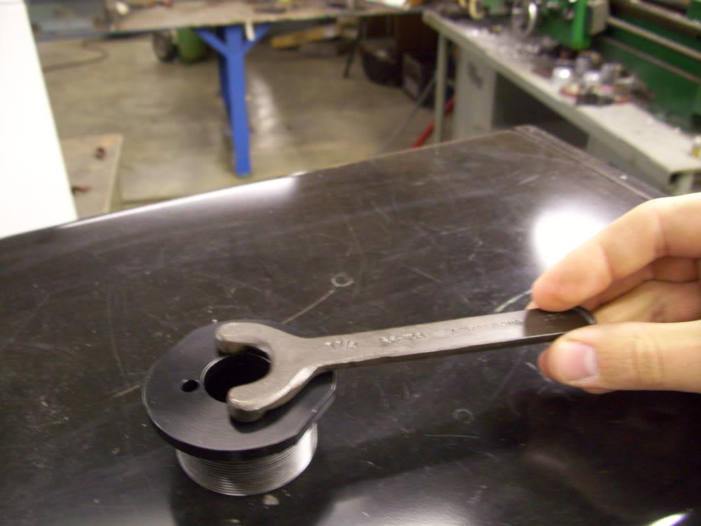
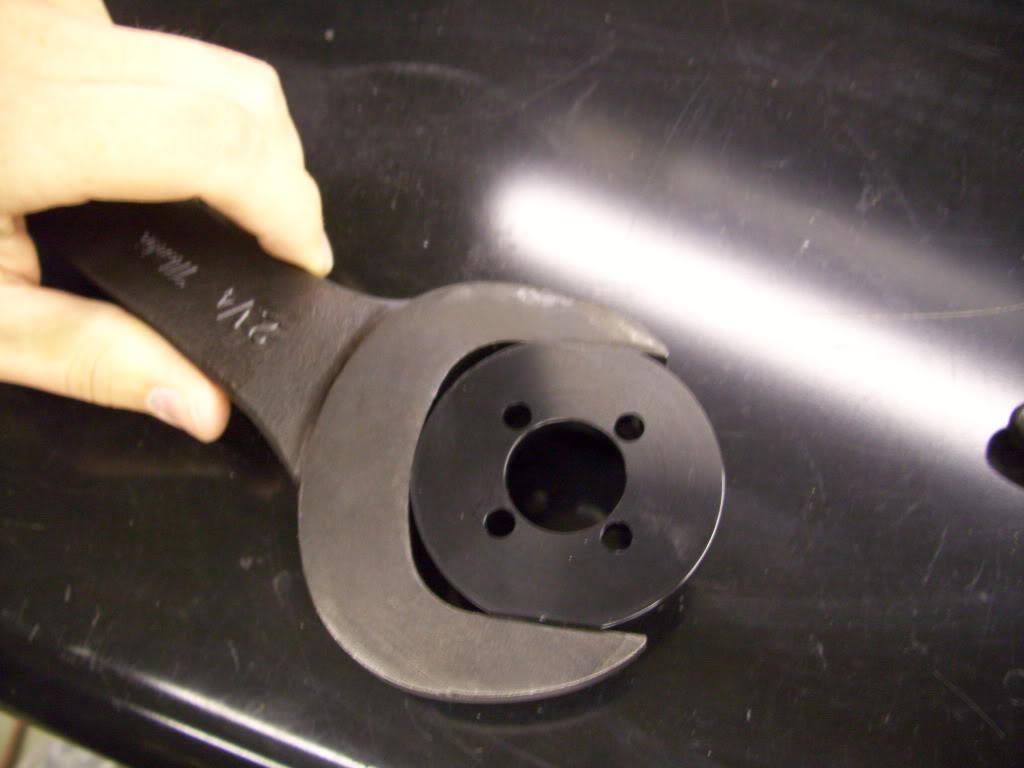
Remember all that machining I did on the strut caps? That was for these two wrenches. I use the wrench flats mostly, then the spanner holes are just in case it seizes up so I can still disassemble everything in the future.
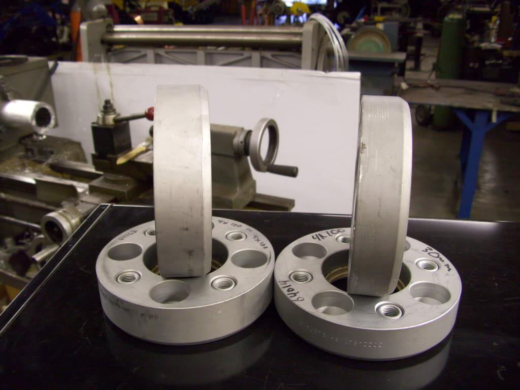
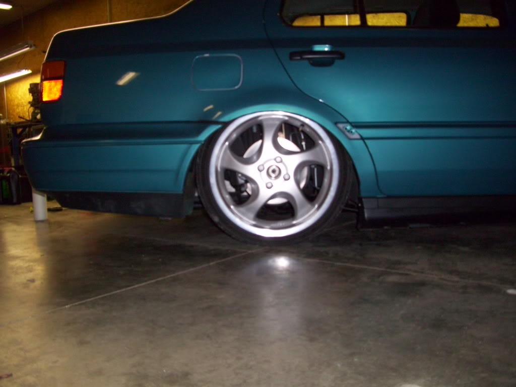
I also got the new adapters from GMP Performance. The Artecs use the RH adapter system wheel mounting. The wheel itself is ET60, they came with 25mm adapters to make them ET35. I ordered a pair of 30mm adapters and a pair of 35mm adapters. These are the ones that ended up in the car, for final offset of ET30 and ET25 front/rear. That doesn't mean a whole lot since the whole rear setup is completely new!
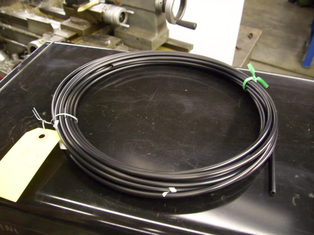
I also got some new 5mm vacuum hose from Mcmaster for the rear vacuum hose that I melted.
September 12, 2009
Juiced.
Youtube video of hitting switches for the first time!


I drove it a few miles down the road to the gas station; it felt so great to get it back on the road!!!

So after all was worked out, the car was still 1/2" too high. The springs I ordered were too long, the frame was not on the ground. Failure. After a lot of testing, I figured it was just the springs, which was a huge relief. It sucks I have to buy more springs, but I really can't complain because I can have the car on the ground with a phone call and a credit card number. New springs on order from Ground Control, 2nd day air shipping!
September 16, 2009
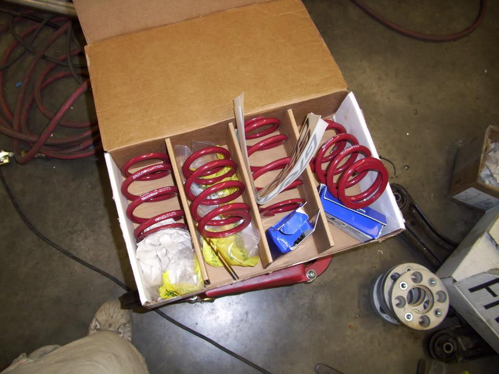
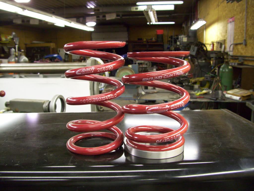
New springs arrive. 5" 425lb/in fronts, 6" 300lb/in rears. The rates are a little different than what I chose originally, but these are the shortest springs you can buy from ground Control.
I machined spacers to go under the springs, I didn't need it a full 1" lower, I only needed 1/2" lower. Since the springs were 1" shorter, I machined a 1/2" spacer.
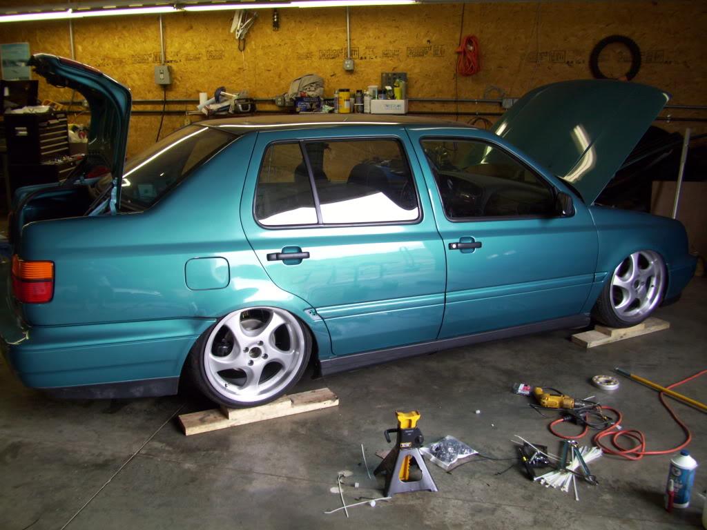
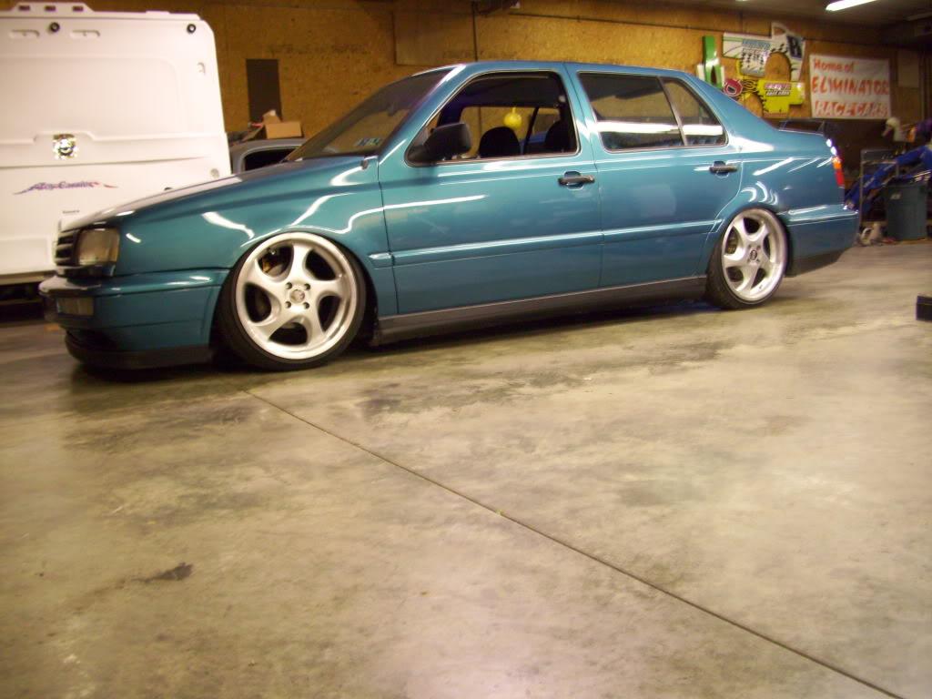
That got the car sooooooo close to laying frame. It was honestly about .030' away from laying frame... I couldn't slip a piece of paper under but it didn't scrape on the super-flat concrete floors!
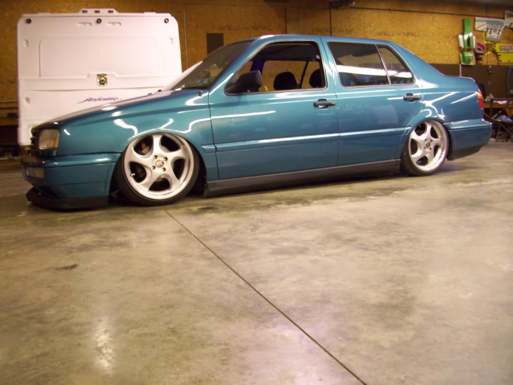
This is about as close as you can get without laying!!!
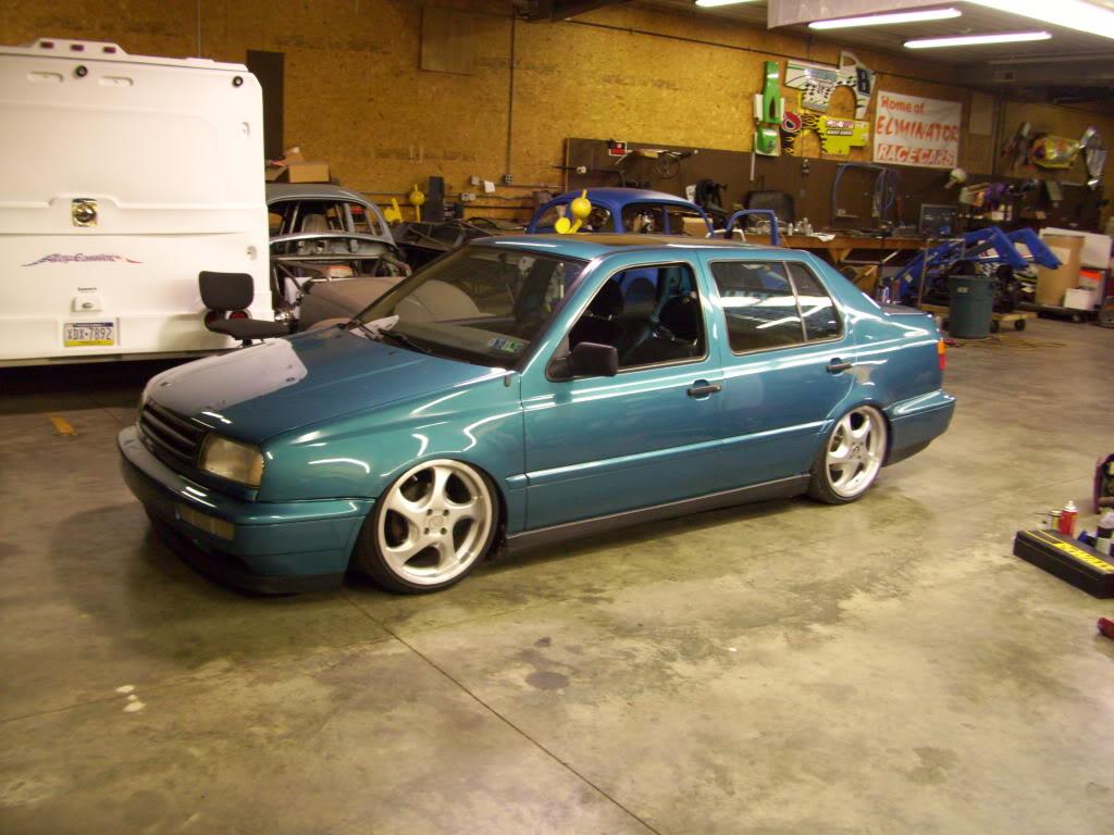
This is all the way up; 1-1/2" above ground lol!
I'm going to bed, I will try to finish it up tomorrow or Tuesday night, I still need to make some updates to the 3D CAD model of the suspension so I can post those pics.
September 20, 2009
I think I got lazy with the dates toward the end... Anything from here forward took place between September 16th and September 24th 2009. The whole last two weeks was a blur, I honestly have better memory of the April/May stuff than last week
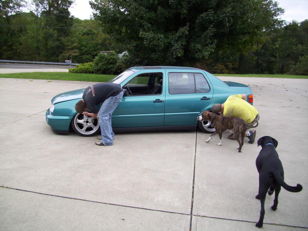
I forgot to take pics (was in a hurry) but I cut two very small notches for the front tie rods and the car laid on the ground. That's all it took to get that last little wee bit.
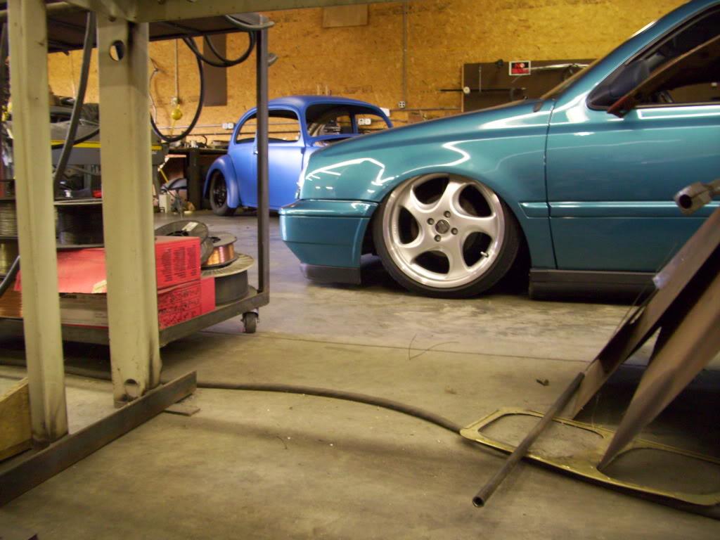
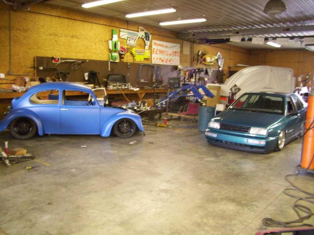
My buddy's beetle in the background.
I got this sweet new cone filter. The first one I ordered way back in June 2008 was wayyyy too small. This one is just right. K&N from Summit.
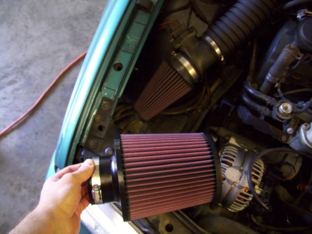
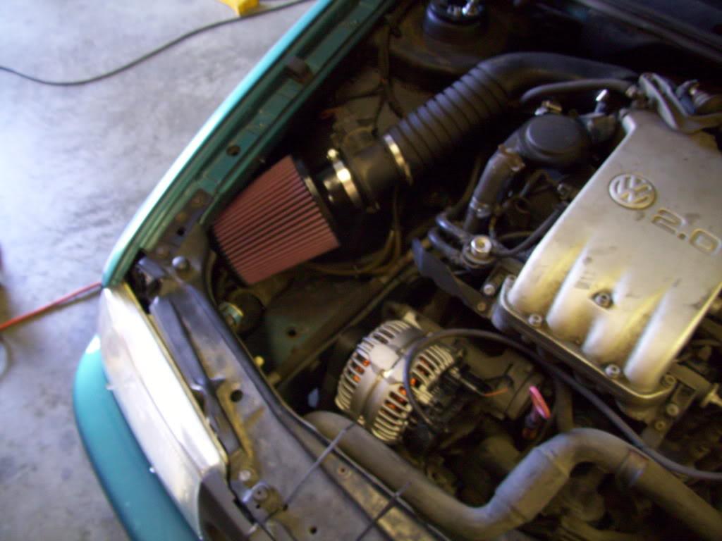
+50 horsepower, minimum.
It turns out I will be driving myself to H2O, so I decided to throw this sweet stereo back in. I had my front (only) speakers hooked up to the amp back years ago, so I didn't have any tunes until I put this amp rack back in. I know I know... try to hold back your jealousy of the sweet MDF/Jigsaw fabrication I did back in 2004
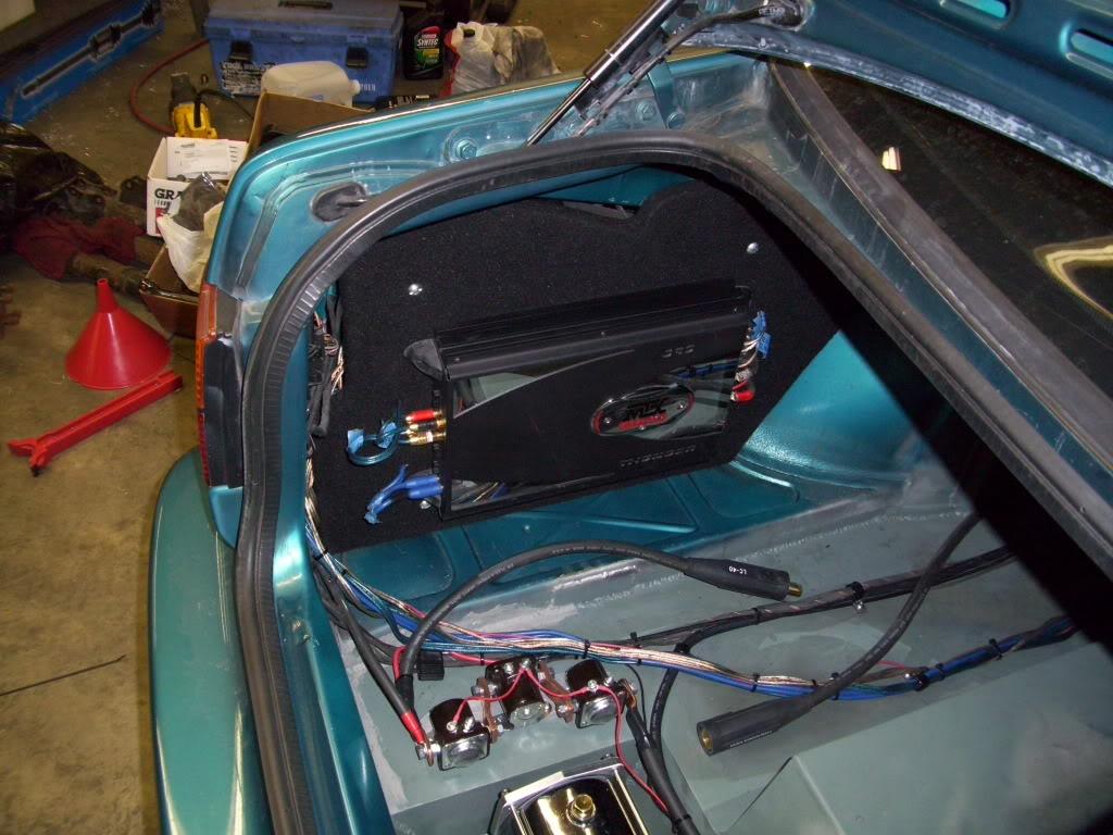
And that finishes off the trunk. Done!
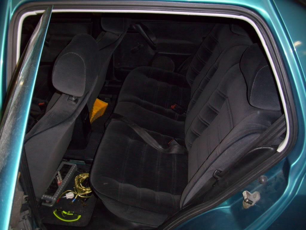
I got the rear interior all reinstalled.

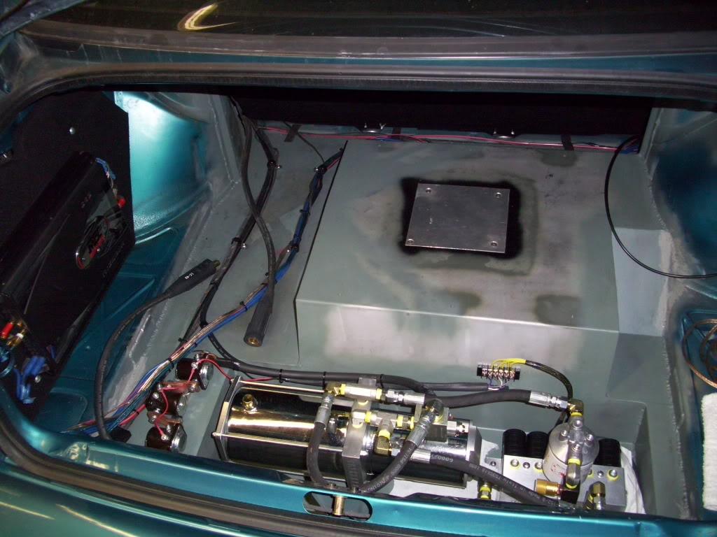
At one point prior, I had my dad hook up a current probe and measure the current draw when the hydraulic pump is running. It draws 180Amps when lifting the car, so my 200A fuse was a great guess! It's a bit undersized, I should probably run a 220A or 250A, but it was all I could find on short notice.
To handle the extra strain on the electrical system, I decided to upgrade to an Optima Redtop (34R) battery. I should probably be running a dual battery setup, but it's worked well so far since I dont' play with the switches too much.
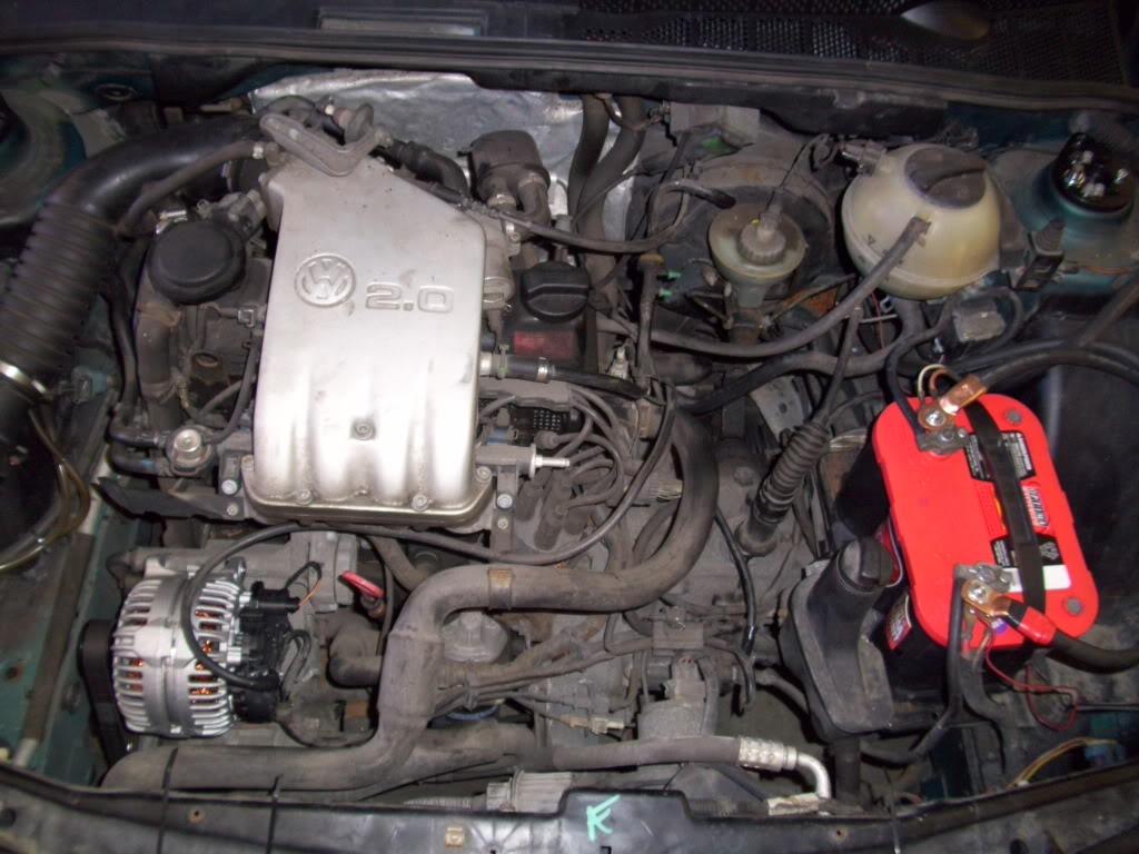
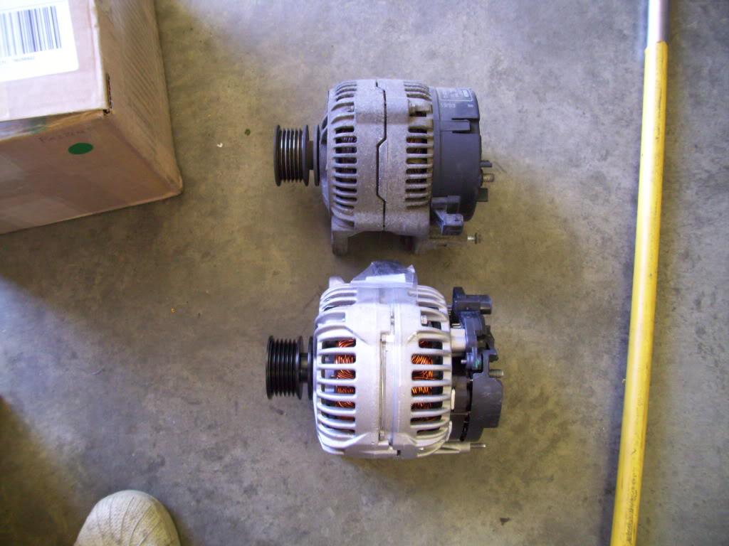
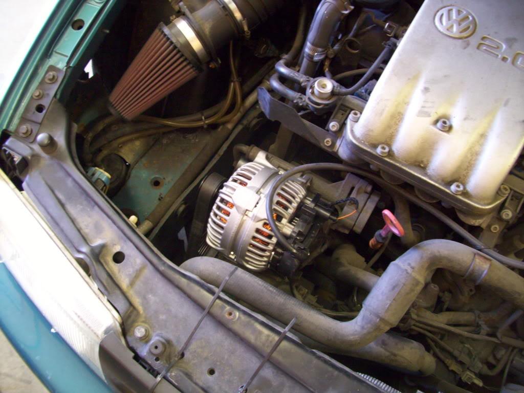
I ordered the VR6 alternator upgrade from GAP.
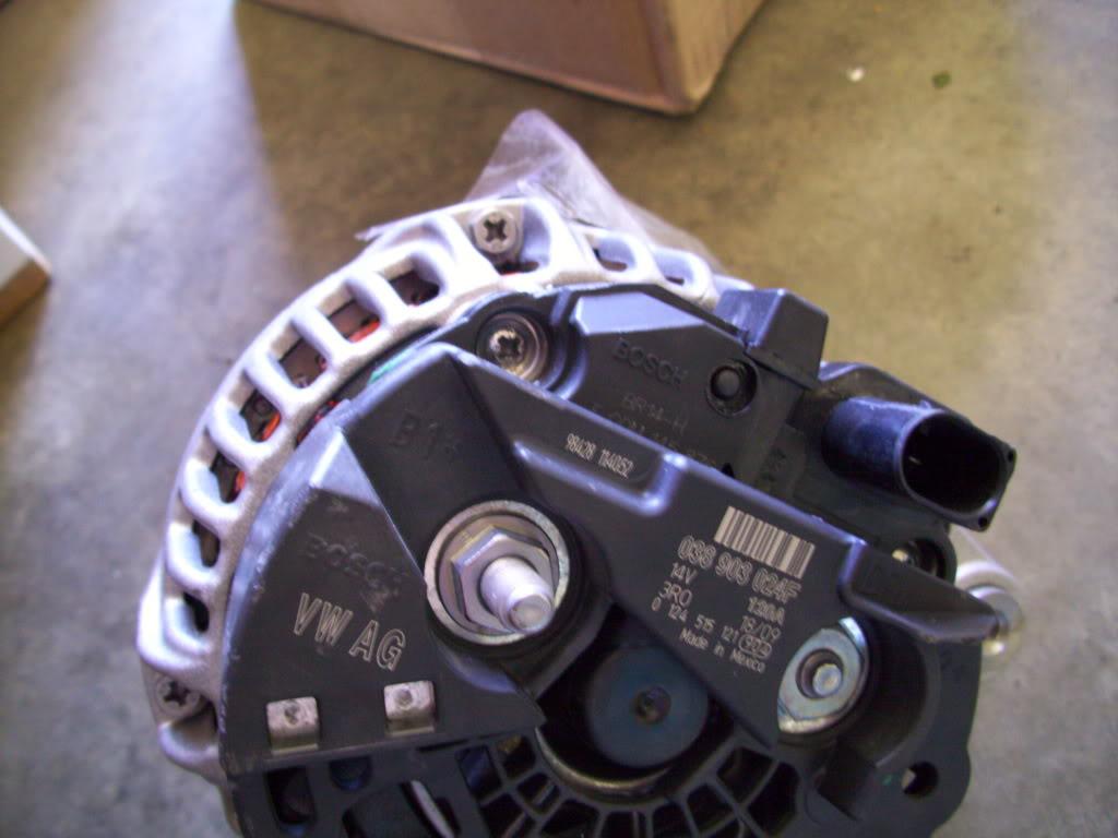
The stock alternator is 90A, the VR6 unit is 120A. I priced out some 200-400A monsters from the performance car audio scene, but decided this would be just fine. I'm not hopping like a lowrider, so my average current draw is still super low.
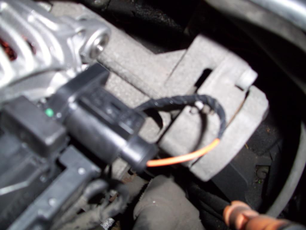
The plugs are different in the VR6 and the stock alternator, so I had to splice in the new connector.
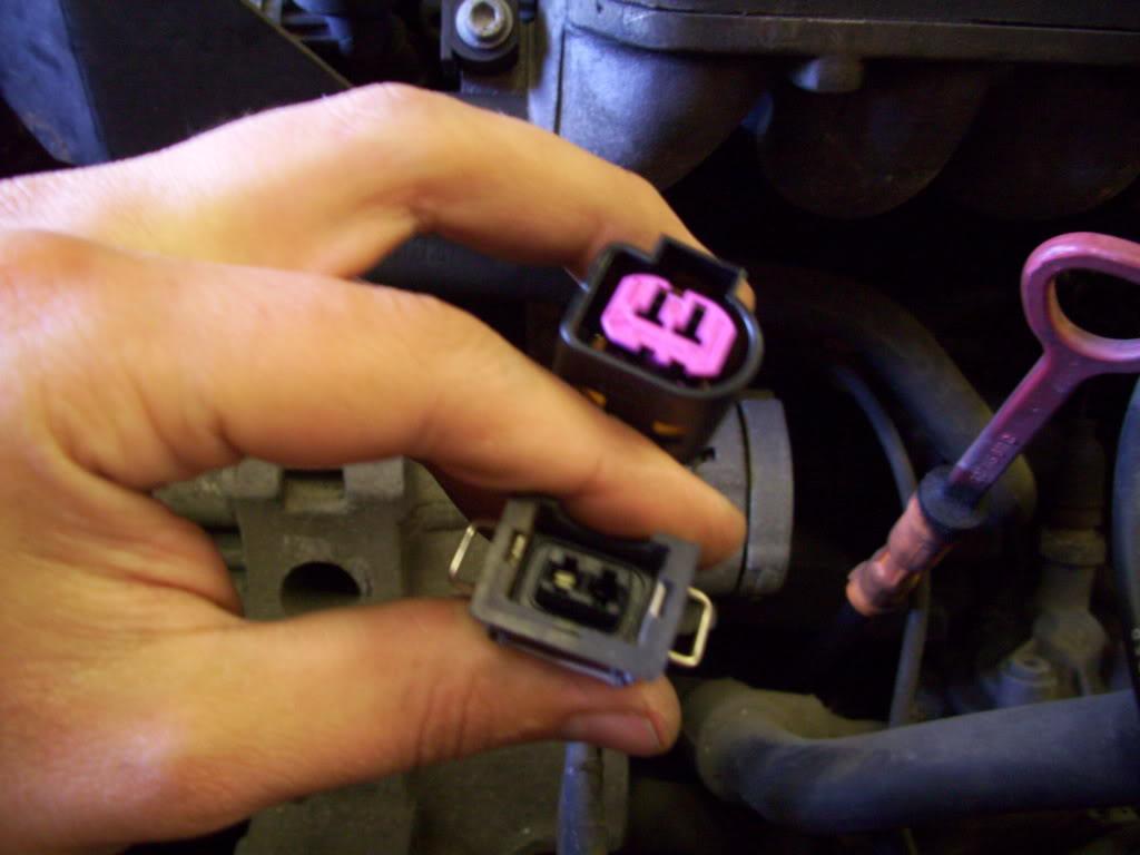
This is the only bad thing you will EVER read about GAP... I spent all day F'ing around with this F'ing plug trying to get the pins out without the proper tool. They couldn't include a $1 wire pigtail?!? I ended up taking a donor clip out of an old harness, which I smahsed the plastic connector off, then soldered it onto the old wire. Alright enough rant, GAP is still badass
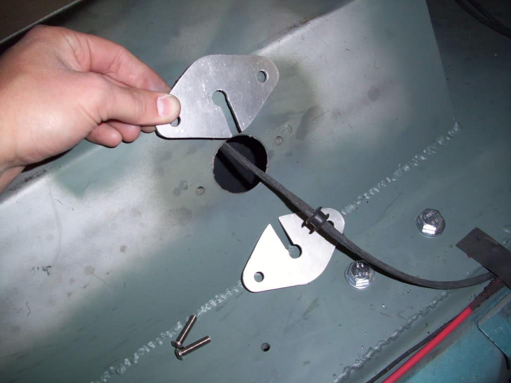
I needed to make some sort of connector/bulkhead for the fuel pump wiring, which was just going through an empty hole in the floor. I had this planned out months before, but finally got around to making the bulkhead.
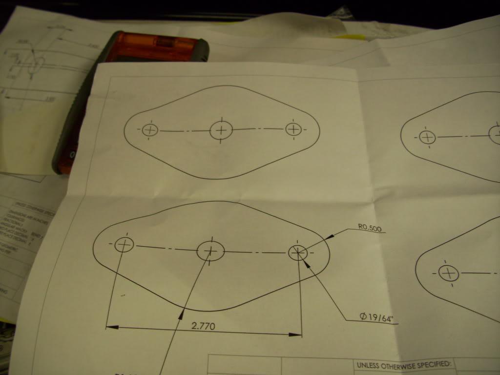
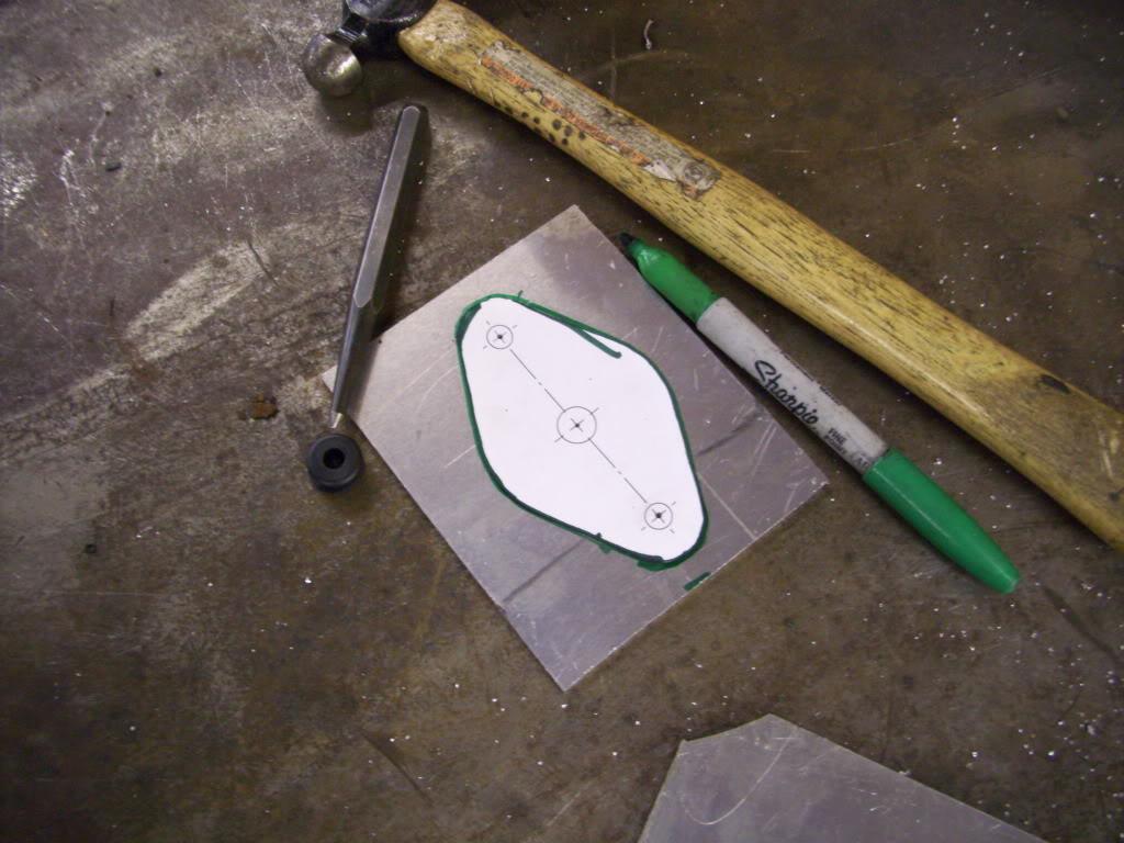
I've used this method for a lot of the fabricated parts: Print a pattern, trace and cut out, clean up with a file/grinder/sander, then weld. I did this with all the strut tabs, some of the fuel cell mounts, fillerneck parts... I finally decided to take some pictures of the process.
I made a CAD model of the plate and printed it out in full-size 1:1 scale.
Traced it onto some 1/8" aluminum plate
Cut it out with a jigsaw. Don't hate on those cuts.
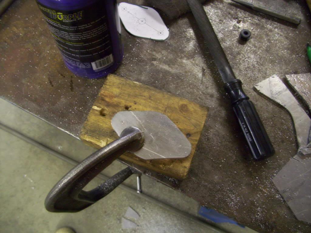
Now with this particular plate, I cut two identical plates and slotted them. You'll see why in a minute:
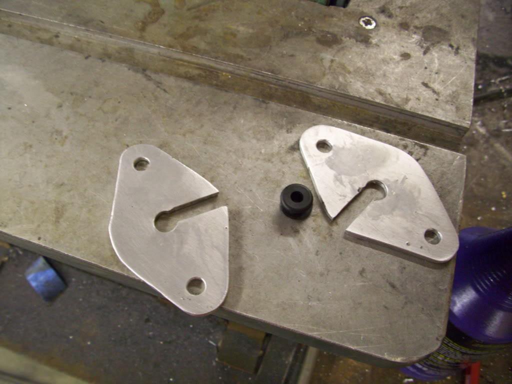
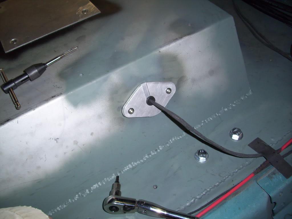
You can see the rubber grommet around the wire, which will fit snug into the holes. Using this split grommet, I can seal up the wire without removing the big fuel pump connector from the end. The connector itself barely fits through the 1-3/4" hole in the floor, but this bulkhead plate design allows me to seal it up. I even had more gasket material on the back sides (can't see from the pics) to seal it up. It's not a 100% seal, but close enough for me.
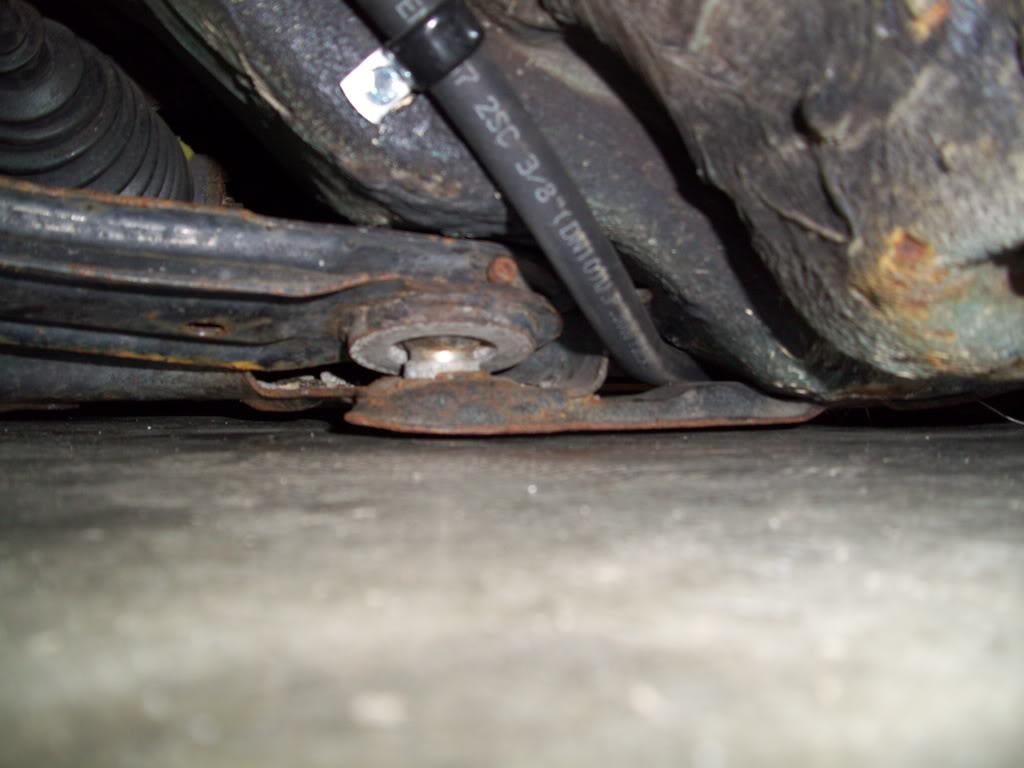
I also made all these shims to move the rear "steering rack" upward.
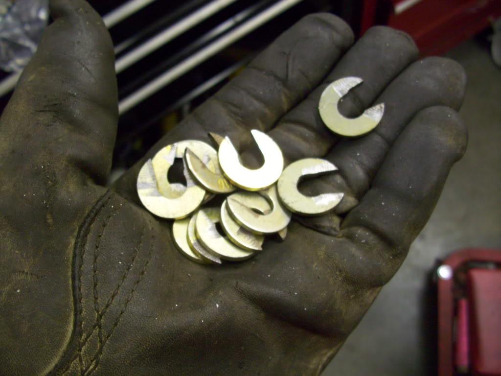
I didn't take any pics of this process, because it's hard to capture with pictures, but here's a brief explaination.
When you lower the front of a mk1/2/3/4, the wheels toe-out. The left wheel is steering left; the right wheel is steering right. I knew that. Since I mounted a mk3 front subframe on the rear, in reverse, I knew it would toe-in as I lowered it. In order to correct the toe-in through travel, I had to shim the "Steering rack' upward. This is possible in my rear because I don't have an engine or header or steering linkage to worry about; I can just move the rack up and should fix it.
During the initial setup, the car generated a lot of toe-in even with the 1-1/2" of travel in the hydraulics. I shimmed and shimmed, and the rack went up 1/2" and the toe change got better, but still not perfect. This can only be further corrected by building a new rear steering rack which is taller, since I'm at the limit of what I feel comfortable shimming. The car still isn't perfect; I'm not sure if anyone noticed toe-in at the rear but it's there. It's on the "fix it this winter" list
Nice build! Great photos and detail ????
Posted by Diggymart on 4/23/19 @ 12:52:48 PM