You must be logged in to rate content!
13 minute read
Phenoms Cruise control project
Compliments of JonnyPhenomenon @ vwvortex.com
5-17-2010
this just arrived on my doorstep today
complete write up and DIY coming soon...
you got it. I got a whole pile of parts from an audi. cruise control module, vaccum pump, hoses, vac switches, wiring and so on. and this bad boy will make the whole package complete:
its gonna be sweet!
I am a bit nervous that the cruise control module will not work. these things are notorious for dying all the time. even the cruise in my wifes 2002 cabrio took a dump on us over the past few months.
but if it doesnt work, I have a backup plan. I have been working on a design(in my head) for a home made cruise control computer.. its not on paper yet, but ive got a couple extra PLC's kicking around that I might try to make work.. - but Ill burn that bridge if/when I get there.
5-19-2010
Cruise control install started yesterday! unfortunately my battery died in the camera so I didnt take any pics... Regardless, I didnt get very far anyway. I might need some more parts....
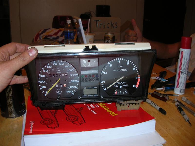
I will be installing cruise in my rocco that has a frankenstein MFA gauge cluster. - a combination of the stock rocco, 89 gti, and (I think) 92 jetta parts.
the MFA consists of the mfa computer which is entirely enclosed in the clock, and the impulse sender thats screwed onto the back edge of the speedo. for cars that have cruise control this speed sensor has two pins sticking out the back of it for the cruise control connector, but for mine, where I intalled MFA and didnt have cruise, I dont have any pins sticking out the back.
after some careful research, I am hoping that I might be able to pick up a speed reading from one of the main plugs on the cluster. according to a pinout diagram I found on a2resource.com, pin T7c/2 should be for a speed sensor. I the question is wether thats in input or an output....
does anyone have a schematic of the plastic film circuit board on the back of our clusters?
here is the speed sensor I have. (its black and on the left of the speedo)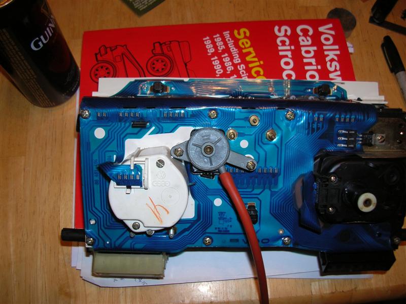
from what I can tell from ETKA, the one I need has two pins on the back of it....
when I get back to work on it, Ill hook a meter up to test if one of the outputs from the impulse sender goes to pin t7c/2
T7c/2 is on the black plug, one pin away from the end on one of the sides. I dont remember what side its on, or which end either. haha!
but pretty much you only have 4 possibilities to choose from. they are 7 pins on each side, two sides, and two ends. Actually, I do think they are numbered on the cable itself, but not the cluster..
but trial and error could figure it out faster than going out to the car and looking at your wires...
5-20-2010
hah! no! that picture was from when I started the engine build. just thought I would throw it in for comic relief.
as for the cruise control project, its coming along slowly, but surely. the wiring is all connected now and ready to go, but I am still working out how I will get it all to drive the throttle.
first Ive got to say, working under the dash behind the pedals is absolutely the worst place on a car to work. I would rather lay in the dirt under a car all day than to spend an hour under the dash. its miserable! a human being should not ever have to bend that way. and all the wires hanging down in your face making it impossible to see anything - ugh. I had to stop for the night. as I was getting so frustrated by it all.
anywya, my plan is to hide the pump under the rain tray, and hide the puller bubble thingy under the dash. instead of connecting it to the throttle body, Im going to attach it to the gas pedal itself. - or the top part anyway.
let me tell you, getting the gas pedal out was no easy feat. they couldnt use a simple circlip in there, oh no.. they used some sort of nightmare made from pressed spring steel, folded over onto itself with a hole in the middle, with absolutely NO way of removing it nicely. I spent an hour alone on that hunk of hell.. trust me, I will be replacing that with a circlip...
here are a few pics to keep you guys interested..
T7c/2 is the empty hole just to the right of the red wire with white stripe. (that wire is going to my MFA)
here it is from the cluster side...
heres the wiring harness I used with only a few customisations.
I added a spring connector for the speed sender (white wire) and a female spade connector for the blue wire with red stripe. (looks purple) - that one goes to G2 on the fusebox.
the red wires with black stripe go to the vac switches and then they splice into the brake switches wire of the same color.
the stock pedal assembly has holes for the vac switches. so thankfully that wasnt a hassle.
you can also see the gas pedal and where it attaches to the cable. I will be connecting my puller just below where the cable attaches to the pedal assembly.
here is where I am installing the puller. there was a hole already in the pedal assembly, but it was too small so I had to bore it out a bit to make room for the bolt.
this is what the spring contacts look like for the T7 plugs.
they have AMP stamped on them, but I dont know what they are called exactly. I would like to find a source for these, as I am running out of old wires to harvest..
thats all for now. time for bed..
I dont think the pics will be necessary, but they would be a good addition to the topic either way.
Ive got it all wired up and almost ready to go. I stole a mini ball joint off an old throttle body, and drilled a hole and welded it in place. the angle of the puller isnt ideal, and its a bit too close to the pedal, but its enough to get by for now. unfortunately, I found that my pump isnt powerful enough to pull it. I think the pump is dead, or close to it. it has a crack in the top of it that I tried to fix with solicone GOOP, but its definitely not powerful enough to suck in the puller when attached to the pedal. so Ive got to find another pump...
Oh, I just had a thought, I have a pump from my power door lock system that I havent installed yet. would be interesting to see if that pump would do the trick...
Oh yeah, some pics...
here is the ball joint installed before I had it welded in.
here is the rod that goes between the puller and the pedal.
I ended up shortening it a bit and using a 10-32 die to cut some threads in it.
in this pic you can see how I secured the nuts. I need to back them off a bit tho.
this black thing is what holds the rod to the puller
anyway, thats all for now. pretty much just need to get a pump for it.")
thanks, I'll do that.
I spent some time trying to diagnose my vaccum pump issue. the pump that I have is just too weak to do what I need it to do. - is possible that its got a bad seal in it or something, but the motor is spinning away just fine. I took apart my central locks pump and fiddled with that for a while, that has PLENTY of power to pull the pedal all the way in, but as soon as the pump stops the air sucks right back out of it. the stock CC pump has a electrically operated valve in it so it holds the air pressure as long as its energized. I would have to find some way to do that with the locking pump too.. - I did recently find a valve on some evap emissions stuff that could possibly work, but it is going against the "keep it simple" approach I am trying for. So I think Im going to try and track down a different CC pump if I can....
I put the rocco back together so I could take it out for a nice evening stroll. sure I dont have cruise yet, but I will soon..
5-22-2010
thanks for the info. I went to a friends place yesterday and tested half a dozen other pumps. none of them had the oomf to pull the accelerator pedal down from under the dash. so I resorted to the central locking pump, and I rigged up a one way valve and a evap purge valve so work exactly like the stock pump does. so the sytem can hold pressure, and bleed it out as needed. unfortunately, in all my friggin around with the cluster, I damaged something and I am not getting a speed signal from my impulse sender at all. - even before I hooked up the cruise control computer my MFA stopped tracking miles..
FUN!
so I brought home another cluster, and I will swap them out sometime tomorrow.
wish me luck
5-23-2010
it happens. I spent today installing a new circuit panel on mine. got it installed and took it for a spin, the MFA is working great, even the mileage mpg counters are working
but the cruise control is not. gottta figure out if the issue is the cruise computer or not. if its the cruise computer I might just make my own with an STM8S-discovery PLC. More on that as the need arrises..
5-24-2010
Ooops! I made a mistake while wiring it up tho didnt realise that till now. I assumed the pump and vent had a common ground but instead they actually have a common 12v. the wiring all tests out OK now, so as long as the computer isnt shot...
Too tired for a test drive now. I'll give it a whirl on my way to work tomorrow. crossing my fingers....
No luck. the computer is bad. gonna try another one. if I can find one...
5-25-2010
I suppose I could bench wire a cluster and hook a drill up to the speedo, then connect it to the cruise control module and hook test lights to the outputs and so on. - I am tempted to do just that.
I just tried out a second passat cruise computer and that didnt work either. I think that the impulse signal it is expecting to not the same format as it is receiving from the mk2 cluster.
the stock speed sensor on the passat transmission is sending 4 pulses per rotation of the speedo gear. if the mk2 cluster is only pulsing the impulse sender once per rotation, then the cruise computer would assume the car was going a quarter of the minimum speed it needs to activate...
Ive got another cruise computer from a mk3 golf/jetta that I plan on trying. hopefully its more compatable with the mk2 cluster...
5-27-2010
PROGRESS!
after trying 4 different cruise control modules, three different clusters with an assortment of speed sensors, a handful of different wiring configurations, and untold hours of head scratching, I finally got it working.
first real problem was a broken trace on my cluster. replaced the cluster and I was able to get a good speed signal out on pin t7c/2.
second, wiring to pumps was wrong. without looking in the manual I ran the brown and red wire to the pump and vent as the common ground, but that was wrong. instead I needed to ruin the bk/bl wire to the devices as the common positive.
from here I ran throough all the tests and everything came out good except for the impulse sensor test. according to the bentley manual cruise control troubleshooting checklist on page 13-27, to test the impulse sensor hook an ohm meter up between pin 5 and ground on the cruise control plug. IO should read 90-110 ohms here, but I didnt. I think its because I was using a sensor from an MFA equipped cluster.
after a lot of deliberation and swapping hardware back and forth, I eventually discovered that the connection between the servo diaphram and the gas pedal had come detached. oops!
once I reattached that piece I found the cruise control worked after all.
the only problemn is that it surges a lot. my pump and vent are both really big, so they transfer the air too quickly. this makes it regulate the speed too aggressively. I eventually just shut it off so I could smooth the ride out a bit.
Later I will try installing a restriction filter to slow the air flow a bit, like a mig welder tip that I used for my MAF hose to megasquirt.
anyway, its working now, Ill post some more as I get it fine tuned.
who knows, you might all get to see me at cincy this year after all