You must be logged in to rate content!
4 minute(s) of a 31 minute read
9-12-2014
After lots of playing around, found a happy medium for AFM input using the TPS. We still haven't done any actual tuning as we wanted the ECU to recognize idle and WOT and it now is. Idle is stable and as long as it goes directly to WOT, it will free rev (AFR's still need some work, but it's a start). Holding partial throttle, get's all wacky. This means we have our minimums and maximums worked out and can change some maps to get it to behave on the street.
9-16-2014
Flowing the throttles today. Interesting enough, the m20 head is efficient enough to max the 40mm TB's in terms of flow, which is probably a good thing when taking velocity into consideration (a 40mm throttle with butterfly should flow 167-ish CFM). Here's some data. Bare head with a port entrance fixture attached, ITB's attached, then stock mani attached.
Here's a graph showing the flow difference. Kind looks like RHD's test mule dyno plot.
And pinned open.
You can see more about our flow testing methods here...
http://www.r3vlimited.com/board/showthread.php?t=261381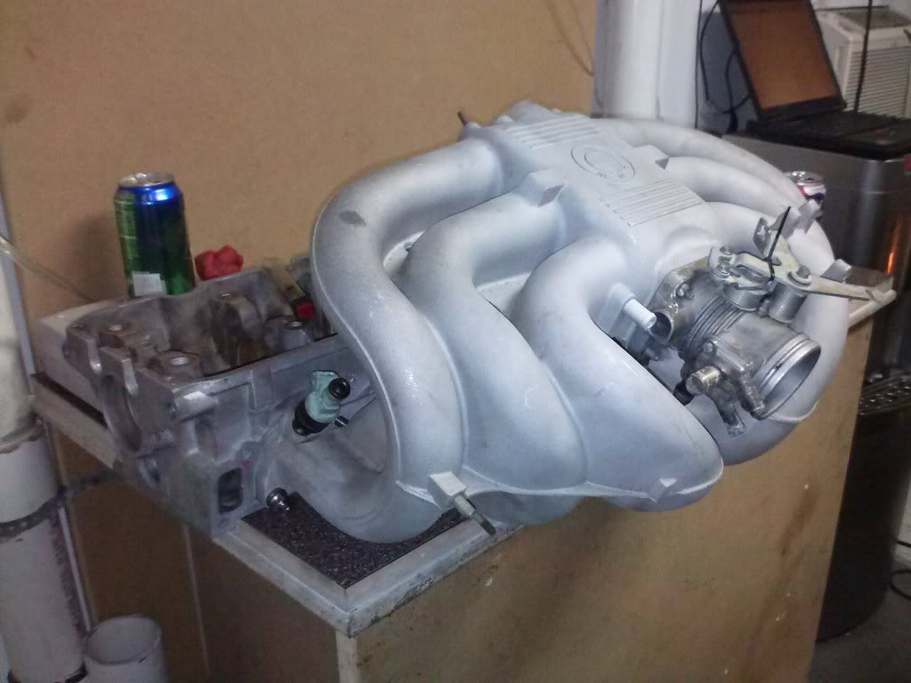
And because pics are fun.
It's because the ITB's are maxing flow. I haven't flowed one individually, but it's right where Dynomation says a 40mm throttle potentially flows. .500" is 12.7mm, doubt many people are running that kind of lift, specially on a stock head. Would have to cut a stock manifold to measure diameter, but remember, manifold runner would be also lacking a butterfly (throttle plate).
This is static flow testing resonance and reversion would be in a running engine.
To add, we should be looking at mid lift numbers as that's where the valve spends most of it's time, the valve sees mid lift twice per cycle.
272 IE cam, and +1 valves. with very little porting.
I stand corrected. The dynomation figures are in 1.5" Hg, not 28" h2o. Doing a conversion with math, that should equal almost 200cfm.
I wish it could have happened now. Wanted to get that (green) Extrudabody car together first to do the tuning sessions to have a base for this (white) car since they will both be running Motronic. More on a timeline budget for the white car than the green one. The green car is getting a plenum built and turbo in a few months, so it will be apart again and can test then. There is a spare set of Rowland here that could be messed with, but no extra TB's.
They both have 272 cams, the green car is an automatic transmission (cough, cough), but they will both hit the dyno.
As afr as the peak TB flow, I looked at dynomation's flow and saw what happened with the flattening of the curve on the chart. the numbers matched max in 1.5"Hg and instantly thought it was peak flow for the throttles at 28"H2o, but now it has me curious.
Did a lot of flow testing today, made it to the stock head with over sized valves (standard valve job to fit valves, no porting). Surprisingly the average flow dropped a lot, very little gain below mid lift, and a loss everywhere else.
Wonder how close they will be the the Jenvy stuff. Do you have pics or dimensions? Just would need one throttle/pair for real world testing. Now that we have benches in two states, we have been pondering the pass around plates to calibrate the benches to the network.