You must be logged in to rate content!
16 minute read
Cheap DIY Brake Ducts
Compliments of adc @ http://www.m3post.com
6-27-2010
For more than a month now I've been patiently gathering materials for my DIY brake ducts project, based on another forum member's trials and results. I figured, since I'm spending $400 on track pads why not spend a little more (plus lots more elbow grease) and put in some brake ducts - it certainly can't hurt.
So what's different between mine and his? Mainly, two things:
- the diameter of the ducts & flanges - he went with 3" and I went with 2.5" for easier routing
- the routing - his come out in the bottom pan (easier install) and mine come out higher through the fender liner (allegedly better flow direction).
Here is my materials list:
4 x 2.5" aluminum flanges
18" x 2.5" reinforced hi-temp silicone hose
4 x 2.5" aircraft quality stainless steel continuous hose clamps
6 x 6mm BMW OEM screws with integrated flanges
6 x OEM BMW threaded clips
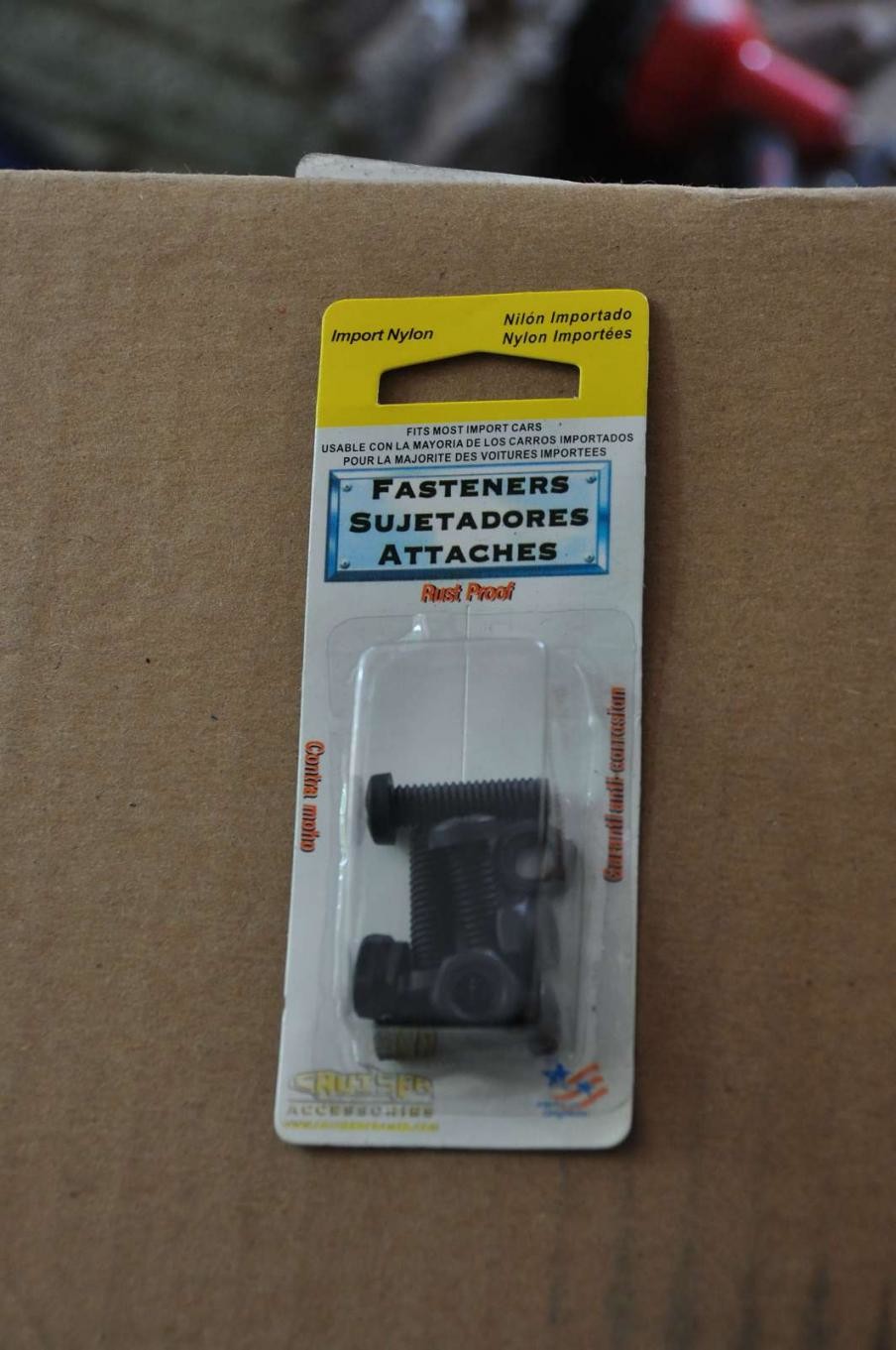
6 x nylon screws/nuts license-plate style
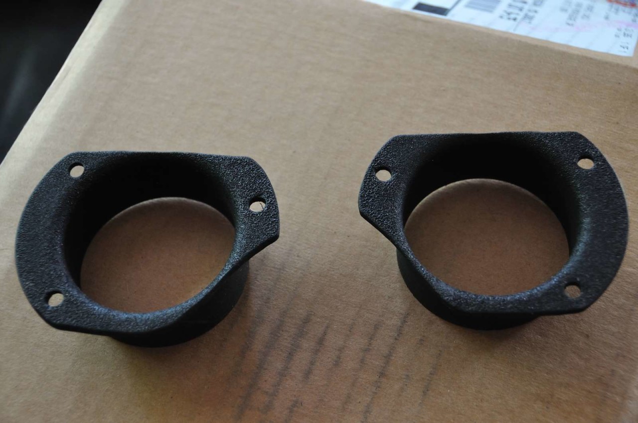
1 x discarded piece of fender liner, manufacturer unknown
1 x tube of hi-temp RTV gasket silicone (or any other automotive-rated silicone)
1 x can of Rustoleum Metal primer (flat grey)
1 x can of Rustoleum rubberized underbody black paint/sealant
1 x roll of aluminized thermal wrapping tape
Give or take, around $100 in materials. If anybody else is interested I can post links for easy purchase of some of these specialized materials - the rest can be easily sourced at Home Depot and any local auto parts store.
The main steps involved were:
1. Removing fuzzy material undertray pieces (one big center piece and 2 end pieces).
2. Cutting holes into the main tray, notching the end pieces.
3. Cutting 2 of the aluminum flanges to fit the front of the car and painting them.
4. Hammering the 2 remaining flanges to achieve a curved flange surface.
5. Creating templates for these curved flanges, to aid in fender liner trimming.
6. Trimming the fender liner.
7. Installing the painted flanges at the front.
8. Cutting and Installing the silicone duct to the front and rear flanges.
9. Thermal-wrapping the ends of the oil cooler hoses, wrapping bowden cables in electrical tape.
10. Installing the underbody panel and fastening the fender flanges.
11. Sealing fender flange gaps, if any.
12. Going faster and faster without any brake fade - hopefully.
Here we go...
Pic 1 - remove the hex head (6mm) screws around the bottom line of the fender liner.
Pic 2 - remove the 10mm bolts at the trailing endge of the undertray.
NOTE - do not attempt to remove the SS nuts (2 on each side) that hold the bowden cable inside.
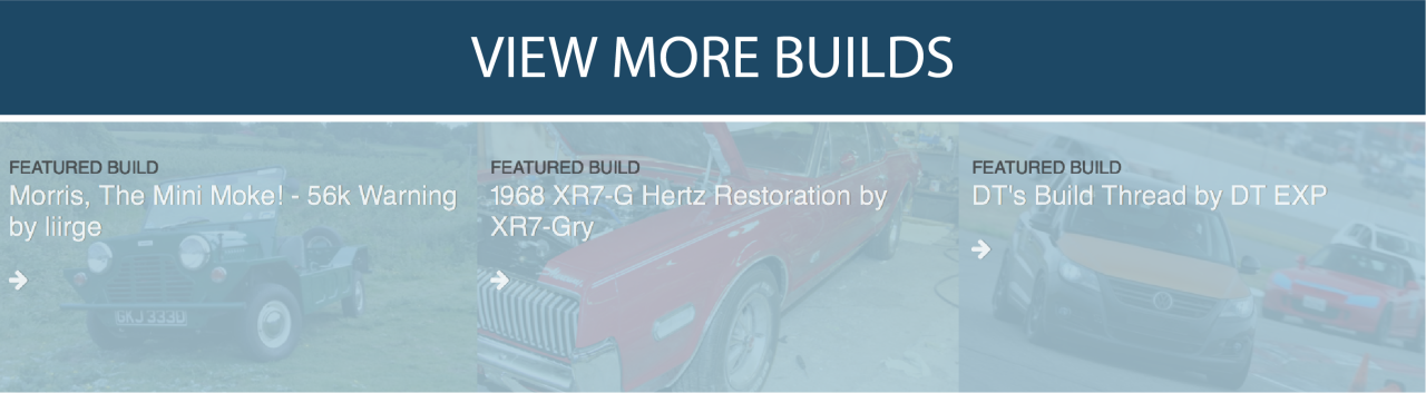
Pic 3 - Undertray removed, this is the proposed path of the duct.
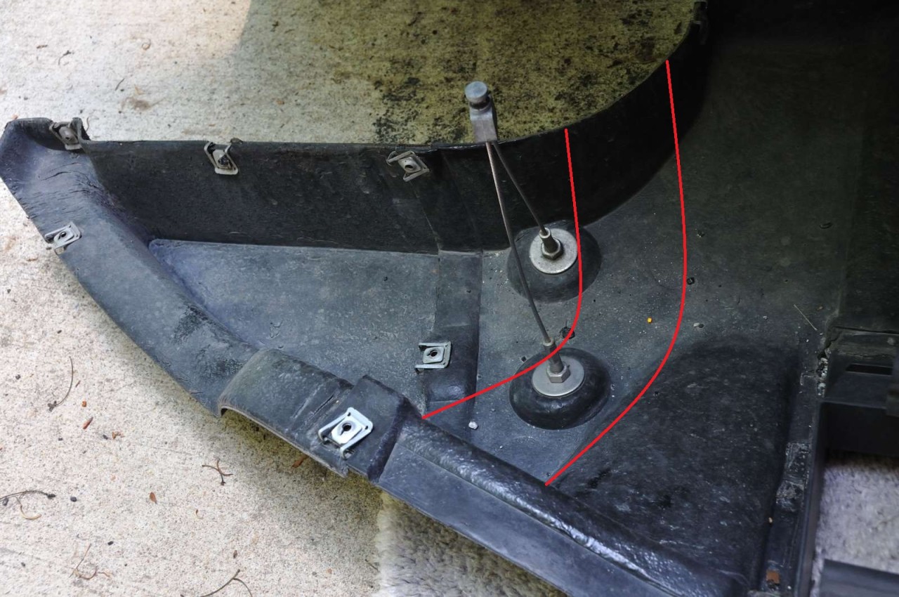
Pic 4 - First hole cut (messed up one of the screw holes).
Pic 5 - Second hole cut - the mangled bowden cable courtesy of my hurried attempt at removing the undertray.
Pic 6 - View from the other side - notice how close it is to the hump profile of the undertray
Pic 7 - Passenger side flange cut and drilled, fits pretty good.
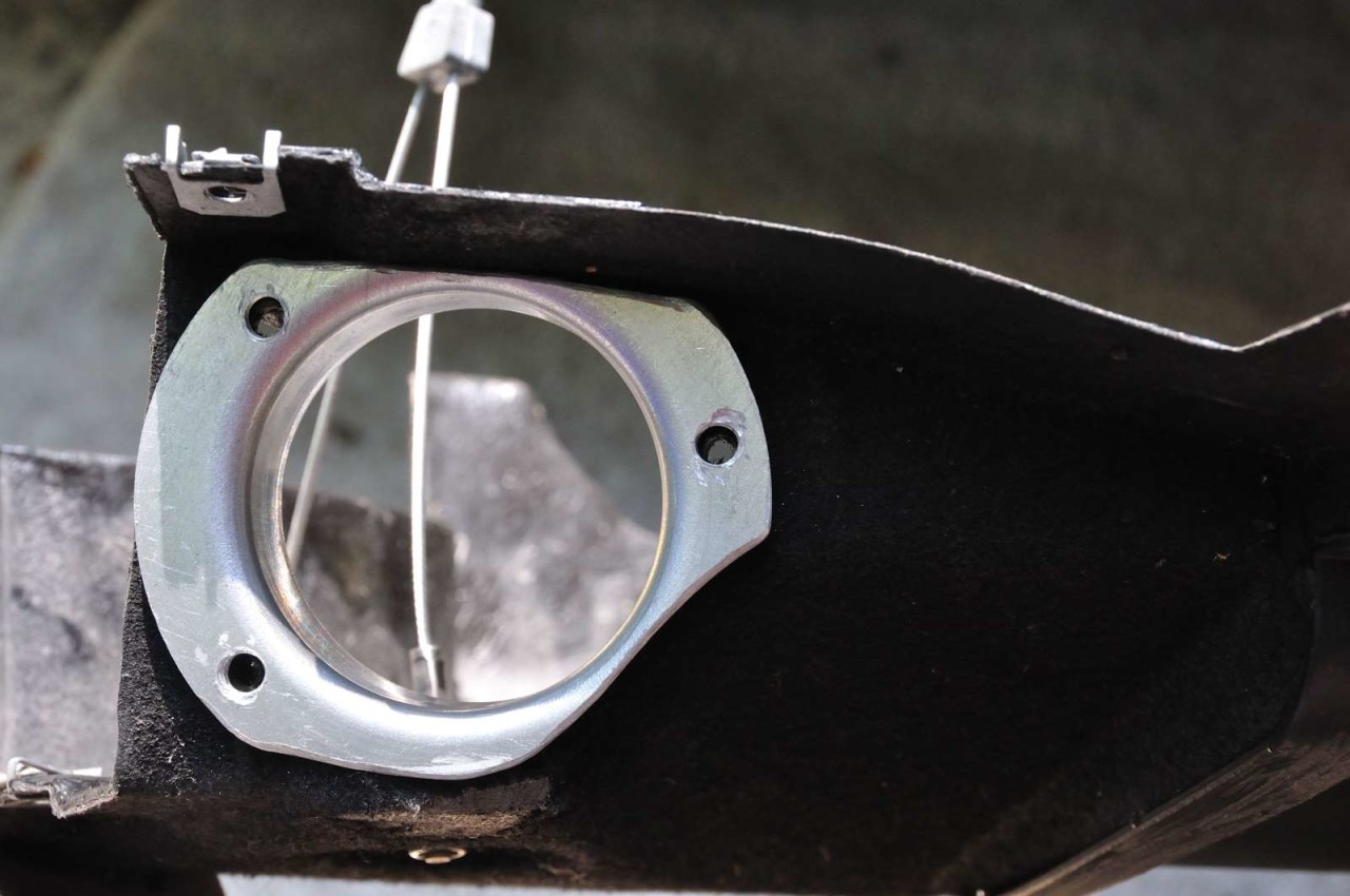
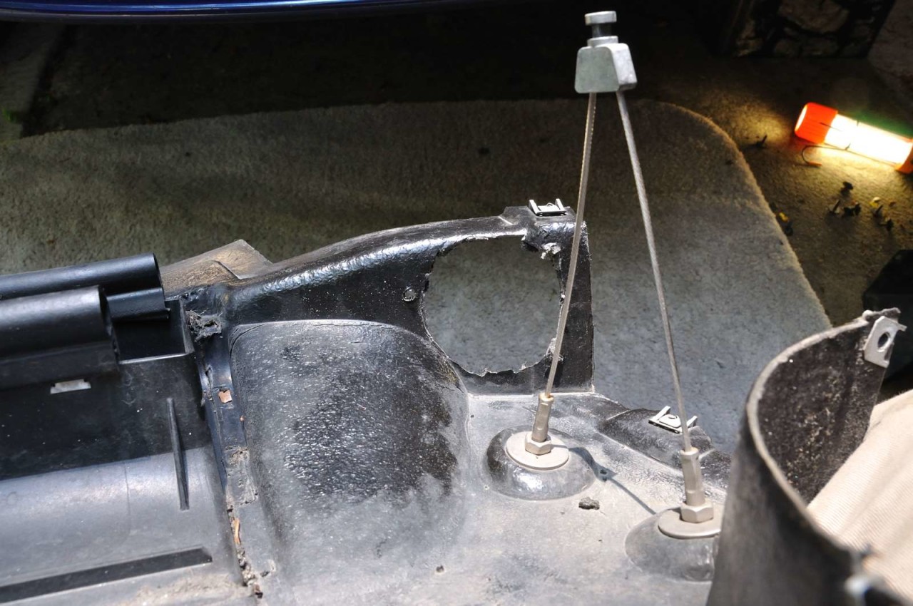
Pic 7 - Driver side flange, just flip the cutting template. (Don't worry about the cable, I replaced it).
Pic 8 - View from the inside of the tray.
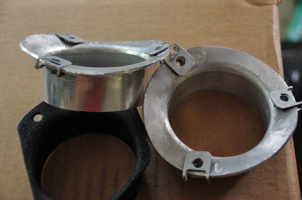
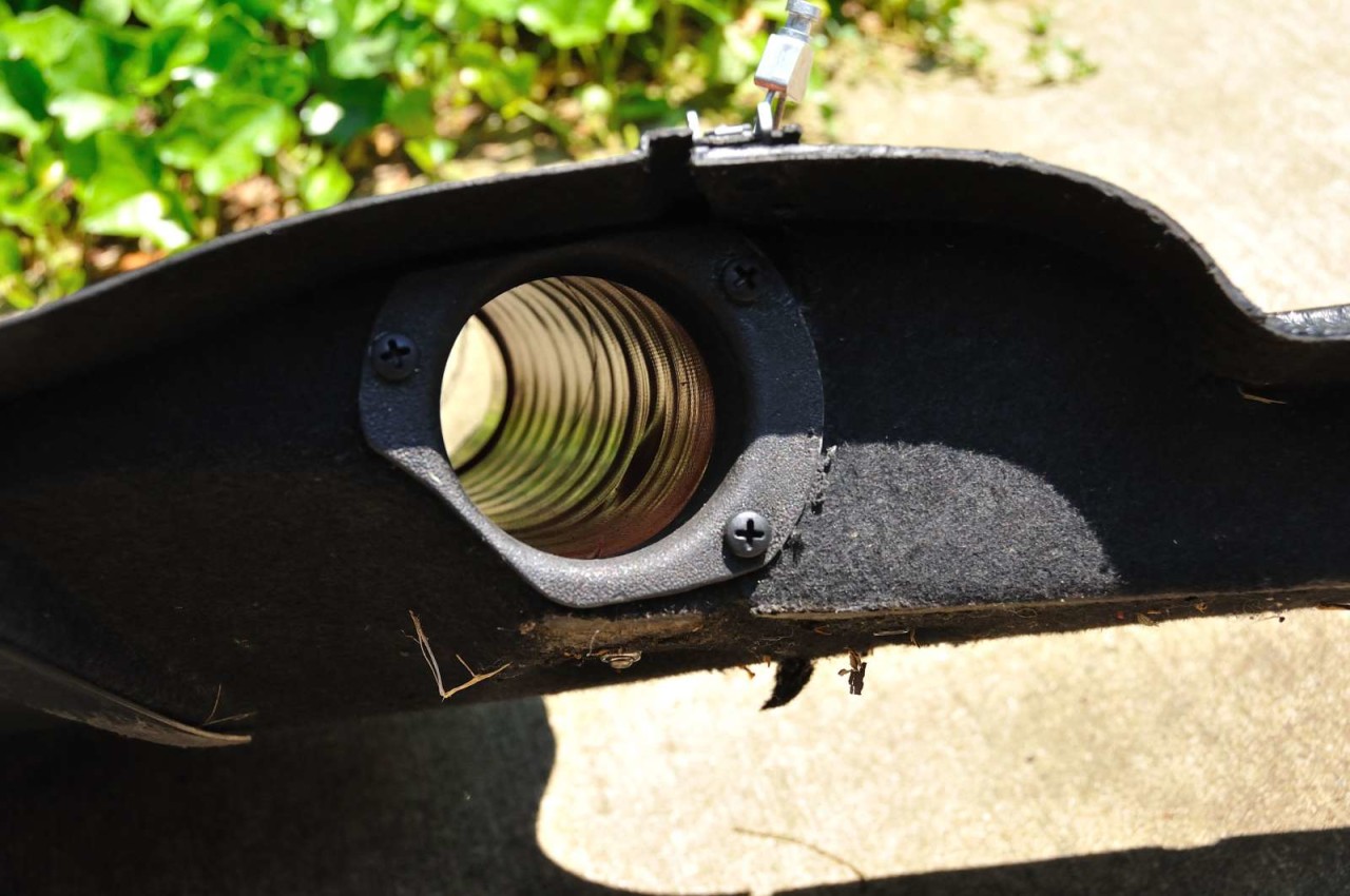
Pic 9 - Finished flanges (polished/sanded, primed followed by rubberized paint).
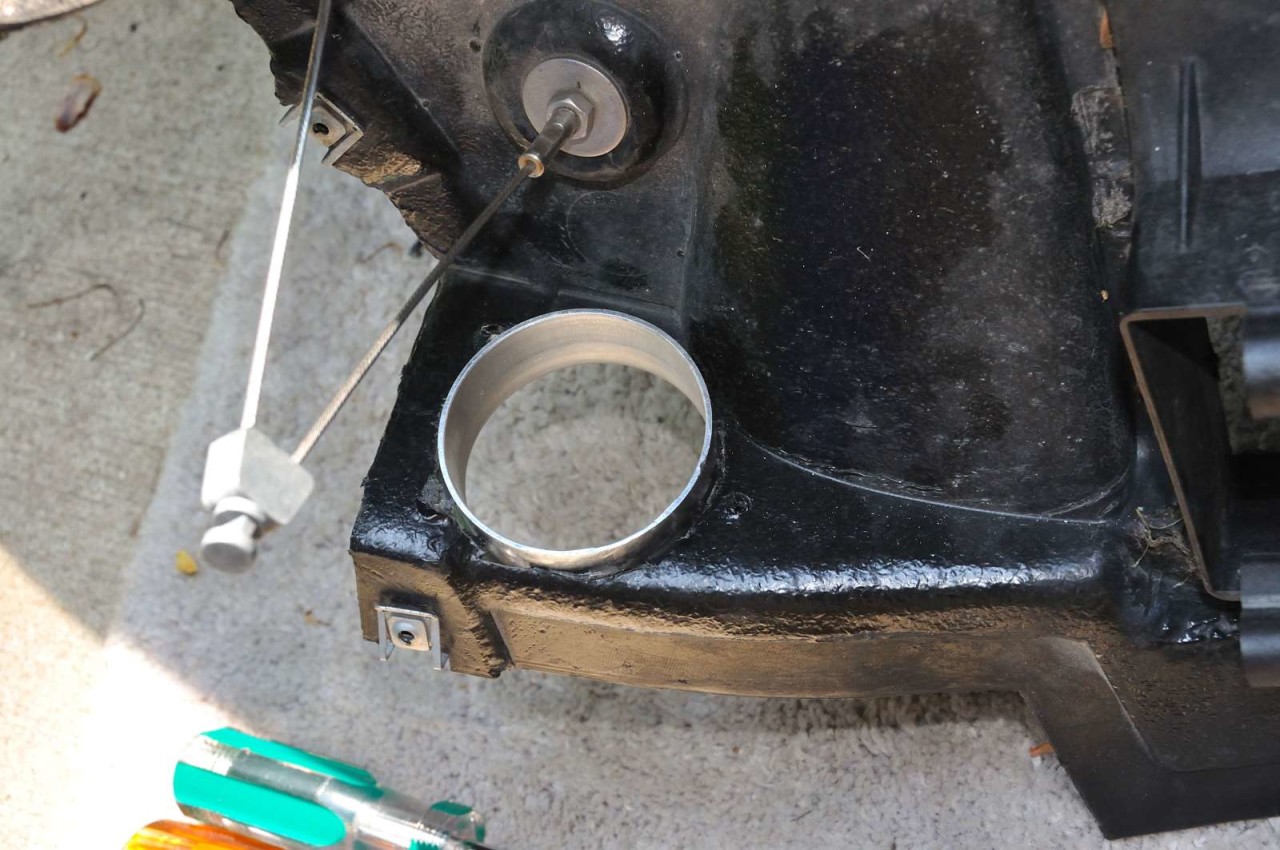
Pic 1 - The other set of flanges, drilled and hammered to an approximate curvature. Plastic donuts are cut from the old piece of fender liner. In my original plan, the alu flange would sit behind the fender liner and the plastic donut in front of it, for reinforcement (like an outside plastic flange). The reality was that the screws were too short to penetrate all the materials, so I ended up not installing the plastic donuts.
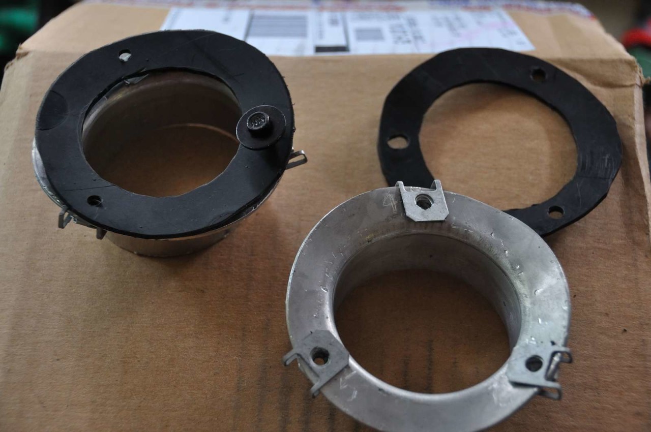
Pic 2 - Different view of the hammered flanges with threaded clips attached. They don't have to be pretty, since they will reside behind the fender liner (but sure would be nice though).
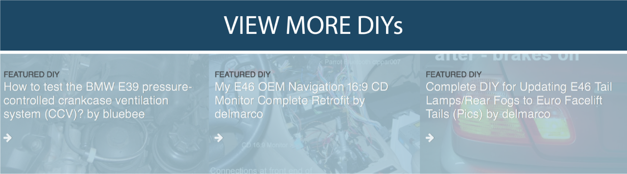
Pic 3 - Front flange installed.
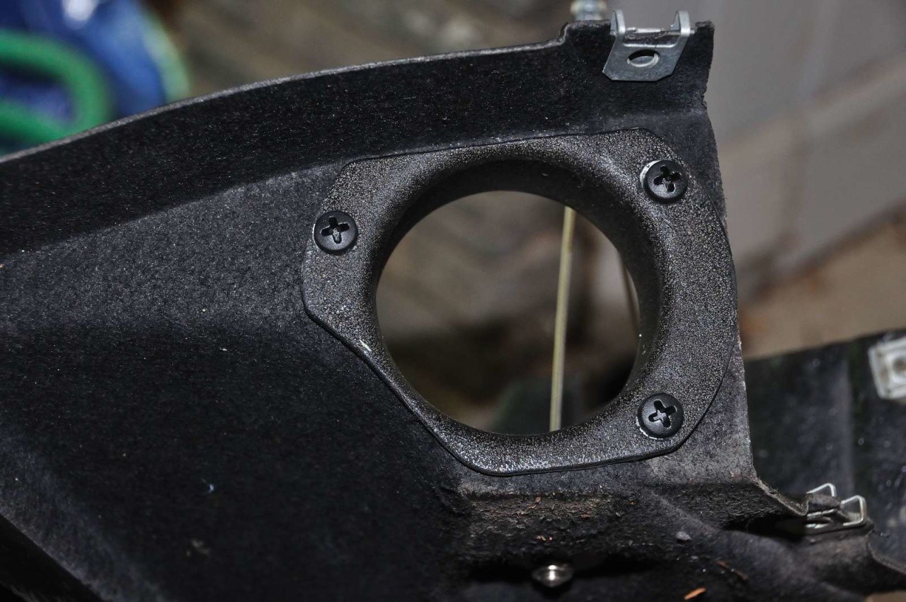
Pic 4 - This is what I used for fasteners at the front (light weight, non-corrosive, sufficient strength and built-in anti-vibration). Get yours at Autozone or similar.
Pic 5 - View from the other side - notice the shiny new bowden cable.
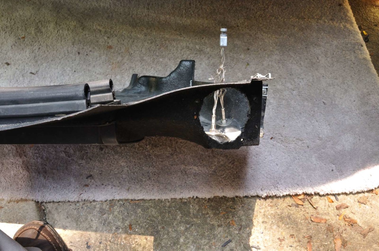
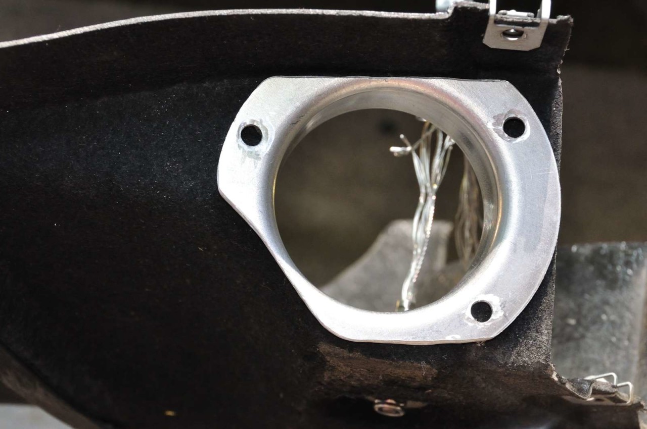
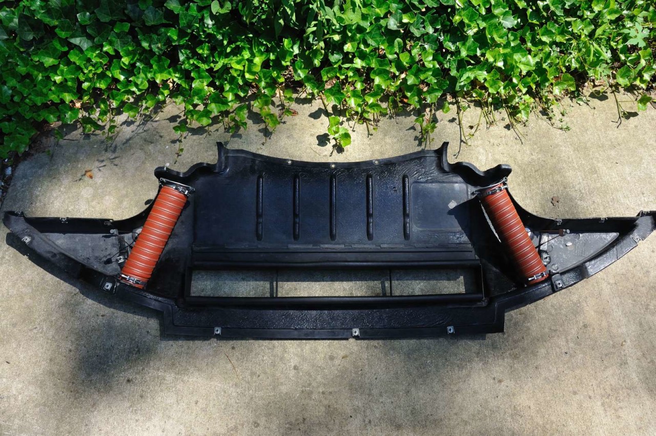
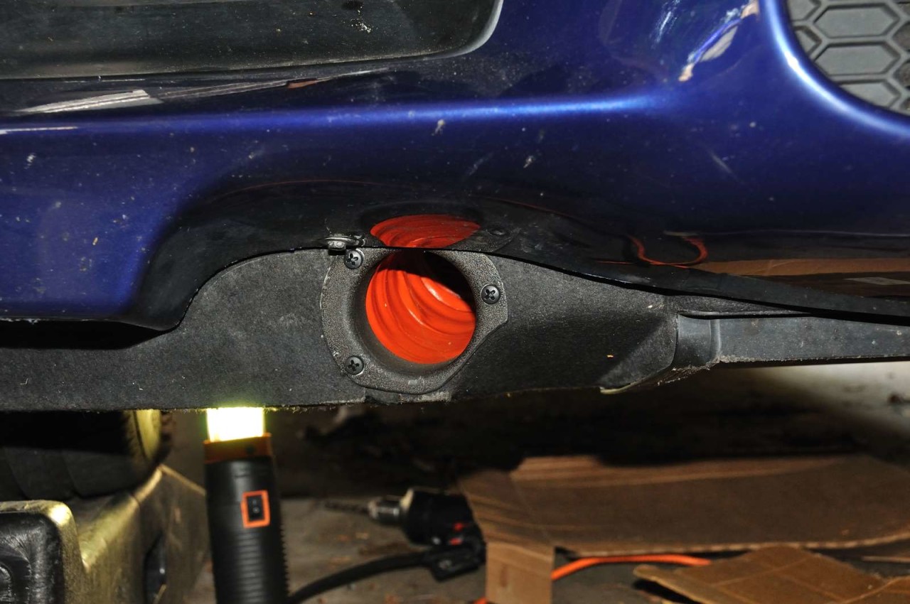
Pic 1 - Finished undertray. Each duct is about 9" in this application. The part of the bowden cables that touch the ducts were wrapped in electrical tape (to make them thicker and less abrasive).
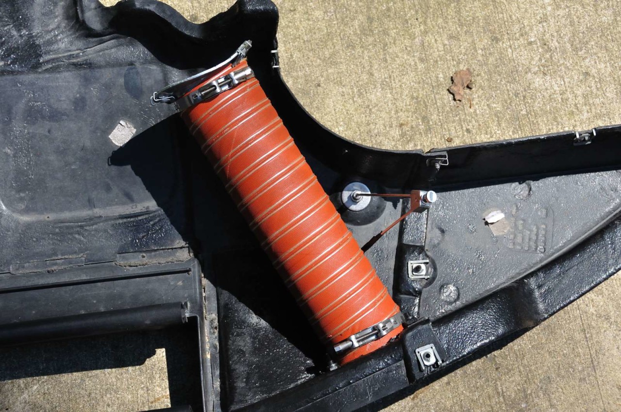
Pic 2 - Driver side detail.
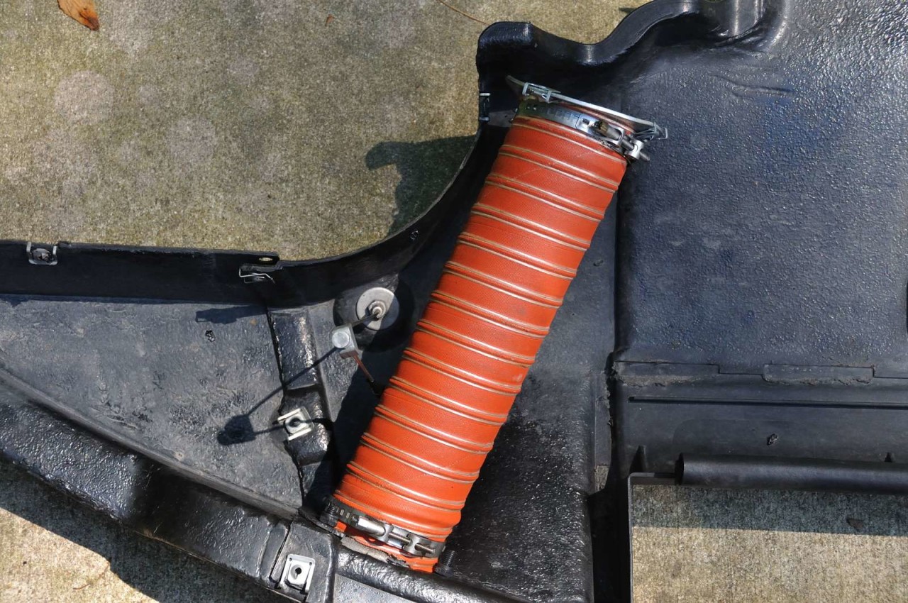
Pic 3 - Passenger side detail.
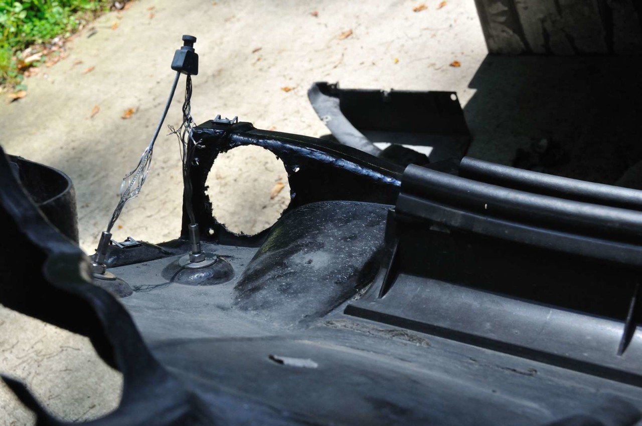
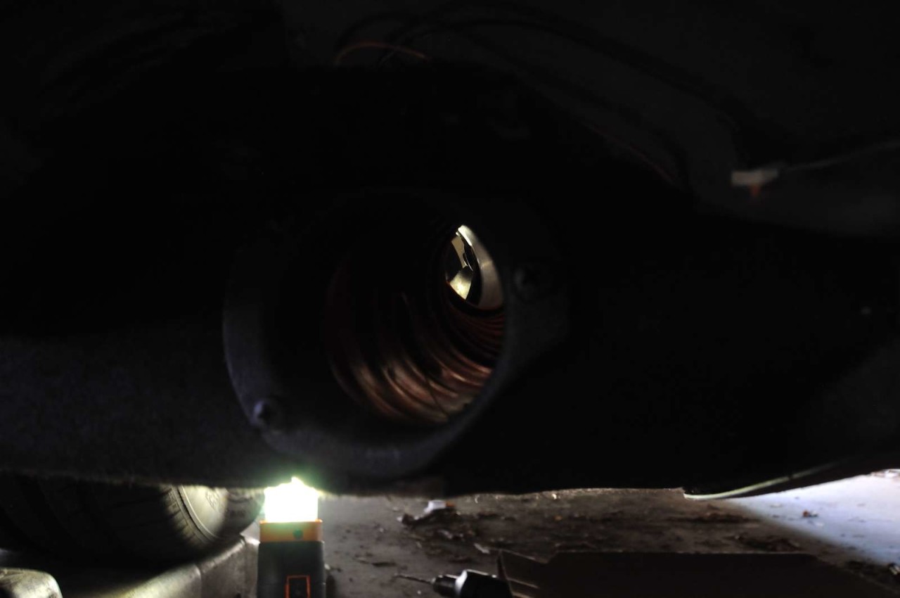
Pic 4 - Air goes through here.
Pic 5 - Mounted on the car. The flange sits close to the overlapping border between the main undertray and the end piece - in order to fit the end piece I had to notch the edge of the end piece to fit around the flange (it becomes self evident once you try to put the tray pieces together).
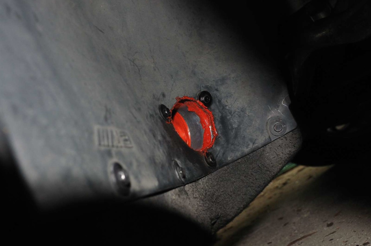
Pic 6 - View from the fender liner. Not very pretty at the moment, I'll clean up the extra goop on my next track prep when I go in to change the brake pads.
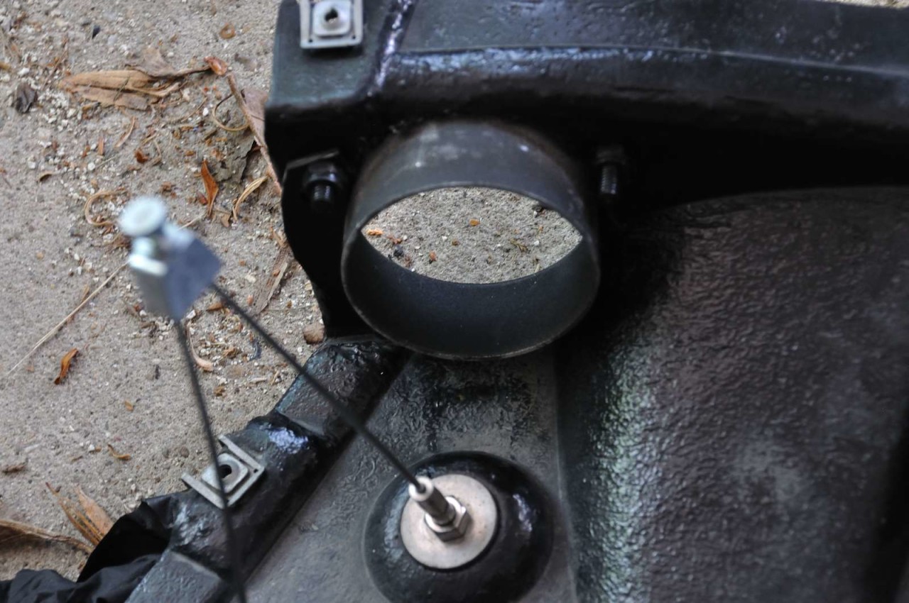
I put lots of goop to seal the gaps between the alu flange beind and the fender liner - air will go through here at over 150 mph, we don't want any tears as a result. I should have gotten some black goop instead of the orange one, but I was running out of patience.
A few more thoughts and details, in no particular order...
- Notice how in the fender side, the bottom edge of the flange lines up with the other fender screws. This makes it easy to position and to drill the hole through the fuzzy undertray and lends strength to the entire assembly.
- The natural (straight) position of the duct gets it pretty close to the fender liner hole - all I had to do is poke my fingers inside and bend it a little bit, then catch the bottom hole with the screw.
- The hose is pretty solid and stiff, rated to 500F if I remember correctly. This should help, since it touches the U-shaped end pieces of an oil cooler. Oil should not get hotter than 300F if everything works well. Just to be on the safe side, I wrapped those U shaped end pipes in thermal tape - so it doesn't touch the brake duct directly.
- Pic below shows the airflow - goes inwards and up a little and curves outwards towards the brake area. The path has been subject to much deliberation - initially I wanted to replicate the path that was posted on the initial brake DIY post, which would have had it exit still in the undertray, towards the interface with the fender liner. That would have made the installation simpler, since the tray would have been more or less self-contained - and should things not work as anticipated, I can always switch to that layout.
- Fender liner pieces are not expensive, around $50 per side - so I had no fear cutting it.
- So why go up and come back at an angle? Well, since I won't be installing backing plates (at least for now), I wanted the airflow to be directed towards the brake area as much as possible. Ideally, it would come perpendicular to the wheel near the suspension arms - but that's impossible, that area is full of important-looking bits and has no space to route a duct.
- By scientifically eyeballing the exit angles, I picked one that still flows towards the brake area, as high as practically possible (there are other things encroaching in the area, such as the oil cooler end tubes). But at the same time I decided to anchor the bottom edge of the flange in a way that would be easily reproducible and not make installation a total nightmare. End result, catching the duct behind the fender liner was not too tricky (but still took about 5 min per side).
- Besides cleaning up the excess goop in the fender liner area, I also need to trim the fender liner hole a little bit - it's not perfectly aligned to the flange on the other side and has a slightly smaller diameter.
- I have the templates for the front/rear ducts in case someone else is brave enough to try to duplicate the setup. I also have some silicone duct hose left, enough for another brake job in case someone is interested.
- It's easy to remove them - I can cut a flat cover piece out of fender liner material (ABS plastic) and screw/glue it in place on top of the openings. Or I can order the fender liner pieces (approx. $100) and even the undertray (approx. $175 if not mistaken).
- Those bowden cables are there, I think, to hold the undertray more rigidly in place at high speeds. Due to the curved nature of the undertray profile, I think at speeds it may bow outwards a little due to the pressure differential created by the airflow. Mine are currently disconnected, just as well as I don't regularly drive at max speed on the Autobahn. If I did, I would have found a way to keep the cables connected - perhaps to figure out a route that goes inside the V of the cables and comes out at the bottom of the undertray.
So, does it work?
The answer is a cautious yes, but I need more testing to make sure. In its maiden test, I taped one of the intake flanges and went for a repeated braking test - similar to the bedding in procedure but not quite as severe (traffic was an issue). I tried to mimic a section of Summit Point Main track braking cycle: 100mph straight, followed by hard braking, 30 to 80 mph ramp up, moderate braking, 60 to 100 mph acceleration followed by hard braking, then coasting for 20 sec and stopping using the emergency brake. I then jumped out of the car and started measuring on both sides.
I noticed a difference of about 10-15F between peak temps across the rotor. The problem was that my pads weren't properly bedded in, so the temps varied about 50F across the surface (from the section that still has pad material baked in to the section that is smooth metal). Max temp was around 280F so in other words, not very hot.
My conclusion is that:
1. I need to bed my pads in properly.
2. I need to repeat the test at a more appropriate day/hour.
3. I may need another tester so we can jump out of the car and measure left/right at the same time.
4. Ultimate test will be at the track.
Would I have done something differently?
Of course, there was a lot of trial & error in this so I could do another one in just 4-5 hours (minus the time it takes for the paint to dry). But other than that, I'm fairly satisfied with the outcome.
Perhaps I would have compromised the exit location a little bit, by going 4-5" lower and exiting through the bottom part of the undertray. But if you do that, the duct is now very close to the natural airflow under the car so I'm not sure how effective it would be. Decisions, decisions.
I'll report as soon as I can do a better test, and of course from my next track outing. Preliminary observations are that it works - for instance, the brake pinging after the car is stopped, due to the contraction as it cools off, is now mostly gone - which leads me to believe the brakes are now a little cooler.
6-30-2010
Correct, it would be very effective. Matter of fact, I think they would be too effective for street cars - meaning in cold conditions they may prevent your pads from reaching optimum operating temps, plus may direct extra water to the rotor area.
I had other concerns as well - mainly having to do with routing of the duct and anchoring it.
No matter where it would exit, you'd have some 12" or so of it flapping about in a turbulent area, so you'd need to anchor it. I understand some people have anchored it with industrial zipties to the suspension arm, which I don't feel comfortable doing.
Another aspect is routing - it would be a bit more difficult to get it to route almost perpendicular to the rotor surface (you'd need that to have room for the duct when the wheel turns inward). Not impossible, but more difficult.
Then there's the backing plate - to anchor the duct to the OEM backing plate, you need to weld - which I'm not equipped to do. (Plus concerns like rust-proofing afterwards). I think if I'd have access to an OEM backing plate with integrated flange (like the ones in the GT4) I'd probably give it a go - but I think those cost 1200 Eur or some other stupidly large sum. Just not warranted for my use, I think.
So main concerns were: anchoring and bad weather (rain, winter) usage.
If anyone is considering going the full route to the backing plate and lives in the Northeast, I'd seriously consider some way to block the front flanges off in the winter.
1-14-2011
Ouch, tough crowd...
Did a track event with Trackdaze on Summit Point Shenandoah and the excellent news is that I pretty much forgot about the brakes. What this means is that for the first time with the E90 I had to concentrate on all the other aspects of driving and the brakes were there for me, lap after lap, no matter how fast I went.
I still cannot compare perfectly with Summit Main, where the speed at the end of the main straight can reach 150-155mph (and I've seen 145-150) and there's hard braking for Turn 1. In contrast, the highest speed I saw at Shenandoah was 125mph on the back straight, and if I went that fast I had to manage my tires and was on the absolute limit of creating an M3-shaped hole in the surroundings.
Still, Shenandoah has probably more braking areas than Main due to the extra 5-6 turns. All in all it might be similar, not sure.
Bottom line, brakes were a lot more confidence-inspiring than ever before. Pedal feel remained excellent throughout, there was no grumbling or other initial signs of deposits and pad wear was pretty even.
I tried jumping out of the car to measure rotor temps but they were outside the range of my IR thermometer (meaning over 950 F). I'll purchase a better thermometer this season and do a few laps with one of the ducts blocked off, to see if there is any difference. So, more info to follow...