You must be logged in to rate content!
33 minute read
BMW E39 failed radiator & failed expansion tank pictorial autopsy, new questions asked
Compliments of bluebee @ bimmerfest.com
11-29-2010
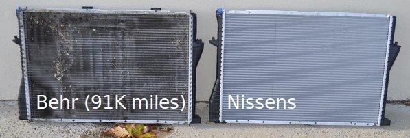
Below I describe an OEM Behr radiator autopsy (verified by date code); and an OEM Behr expansion tank autopsy in a 2002 BMW 525i, with 91K miles on the odometer.
OBSERVATIONS:
- The plastic side panels are held on merely by crimps & a rubber gasket.
- The aluminum of the radiator was in pristine condition.
- There was only a very slight amount of gray gunk in the radiator.
- It was very difficult to find any failure in the plastic side panels.
- An enterprising person could become rich by perfecting a radiator rebuilding procedure that replaces just the two side panels, either with plastic, or aluminum.
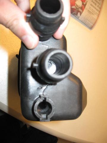
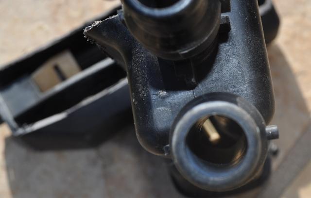
- The expansion tank failed at the nipple during removal.
- The Nissens radiator nipple bulb was much larger in diameter than the original Behr (and BMW replacement) radiator nipple (necessitating a larger hose clamp than expected).
- The radiator failed at the nipple during removal (the nipple didn't fail, the radiator tabs failed).
- The expansion tank failed long ago at the bobbing stick rod.
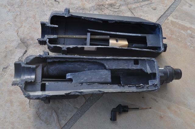
- Cutting the expansion tank in a lengthwise direction revealed inner workings.
- The expansion tank works off of a small disk magnet in the float.
- The float connection to the stick is a very weak point that breaks easily.
HISTORY:
As I was pulling into a parking lot at the mall last week, I noticed a few puffs of steam coming out of the drivers side of my hood. Glancing at the temperature gauge as I idled, I saw the needle shoot to the right from midpoint to about a quarter of an inch to the right of midpoint before I shut the engine down and opened the hood.
I do not remember seeing a "low coolant" warning or any other warning.
I saw liquid spurting from the drivers side, seemingly below the upper hose by a couple of inches, and of to the side, as if a seam split. When it cooled I filled the radiator with tap water and bought a few jugs of water at the mall to keep in the front seat, just in case.
I unlocked the cluster, by memory, with a few mis-attempts. The procedure was basically the following:
- Press the right cluster button for about ten seconds
- When the first test showed, press the left cluster button
- This shows the VIN last seven digits (IIRC)
- Add up the last five digits of my VIN (e.g., 30)
- Press the right cluster button until it showed the last test (LOCK ON)
- Press the left cluster button until it showed the VIN sum (30)
- Press the right cluster button
- This should unlock the cluster
- Now press the right cluster button to go to test number 07.
- This reads out the coolant in degrees centigrade.
At no point in the 15 miles home did the temperature go above 93°C.
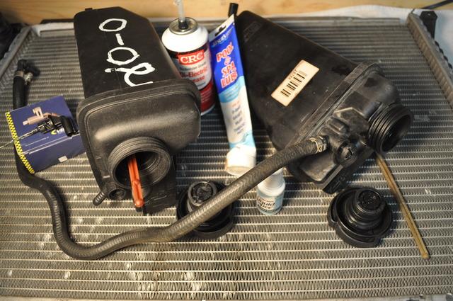
Once home, I proceeded to replace the entire cooling system, using parts previously stockpiled from OemBimmerparts' web site after my previous alternator and belt drive system emergency overhaul.
- One users' example of alternator failure (AAA emergency tow) (1) (2)
Below I will describe, pictorially, the radiator and expansion tank (aka surge tank) autopsy.
One observation worthy of note is that it should be possible to "rebuild" a radiator at vastly less expense merely by perfecting a method of re-crimping the side plastic panels.
Even better would be a method of crimping on stamped aluminum panels in place of the side plastic panels!
I first looked closely at the entire radiator in order to find where it had failed.
It was not easy to see any flaws, which was surprising to me since I had seen water leak out of the driver's side, below the hose, about midway or just above midway on the plastic side. (In hindsight, I should have looked harder while the engine was running; but I just assumed a major leak based on the volume of spray coming out.)
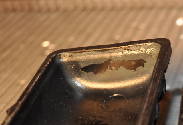
To help me find the flaws, I rubbed chalk over any imperfection I could find.
About the only place on the radiator I could find a flaw was this apparently slight crack on the PASSENGER side (note that it appeared that the driver side was where the leak lay, although there was some liquid at the expansion tank side of the radiator but it could have been thrown there by the fan).
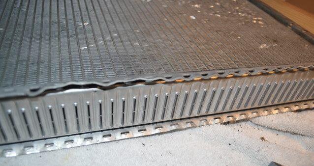
I noticed the only thing holding the plastic side panels in place were an evenly spaced series of crimps. With a pry bar, I easily pushed up the soft aluminum crimps to free the passenger-side panel containing the alleged crack.
Soon the passenger-side plastic panel popped free, along with a rubber gasket along the edge.
I repeated the effort on the drivers side aluminum crimps, which, with experience, came off easier than I had expected.
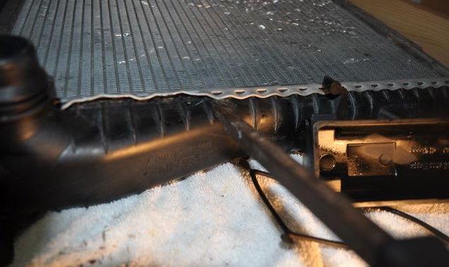
Soon I had both plastic side panels in my hand. Amazingly, the purported crack I saw from the outside did not appear to extend to the inside of the radiator. I was perplexed. In fact, there were NO CRACKS apparent looking at the inside of the radiator.
At this point I wondered if the failure was on the driver side hose itself, or in the expansion tank. However, I re-used the hose (that hose had been recently replaced with the alternator only a month ago due to my clumsy destruction of the plastic bleed screw during bleeding); and a later post will show no apparent cracks in the expansion tank.
Looking closely at the bottom of the drivers side panel, near the drain screw, I noticed a bit of gray clayish gunk. Not much. But a little gritty stuff around the screw itself.
I noticed the same very thin fine gray paste on the corresponding passenger side panel. (Any idea what this is? Is it aluminum dust?)
After looking the two panels over for fifteen minutes, I finally gave up trying to identify the flaw that caused the coolant leak. Whatever it was, it was minute if it existed in the radiator at all.
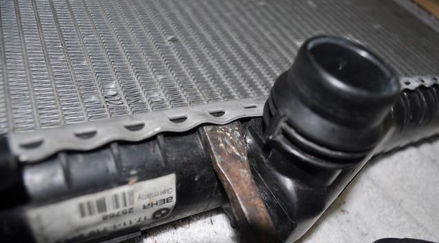
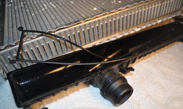
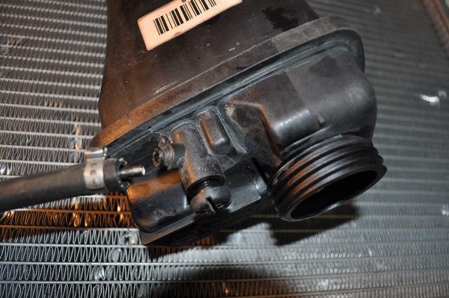
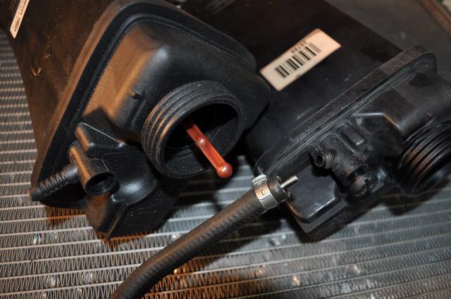
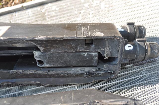
As it's important to be able to remove the nipple from the drivers side of the radiator, I took a look at how that nipple socket is constructed. This, in the future, may be useful because we don't yet have a cn90-patented technique for removing the nipple intact, so as to make a radiator shroud removal a dry affair, without the need to replace the expansion tank overflow hose radiator nipple hose clamp in the future.
It's hard to tell here, but it is worthy of note that this radiator nipple was "saved" during removal. This is a Behr nipple bought at the BMW dealership because the original nipple broke when it was removed during an alternator repair a few months back. While the new Behr nipple went in place at that time without problem, it was nearly impossible to remove that radiator nipple without destroying the two tabs on the radiator holding that nipple in place.
What we need is a better mechanism for removing this nipple intact, to facilitate shroud removals that do not require cutting off the original BMW hose clamps.
- WANTED: An ingenious method of removing radiator nipple
It is also important to note that the new Nissens nipple, which came with the new radiator, was much larger in diameter at the bulb end, necessitating a larger hose clamp than was initially expected, and further necessitating a trip to the auto parts store to find a larger solid hose clamp. The initial replacement hose clamp for the Behr replacement nipple was 11-13 mm solid band. The parts store was missing the size in between; they only had the 14-16mm size. The Nissens bulb end needed something in between (lesson learned). I had to grease and tug and pull and coerce the smaller clamp onto the larger Nissens bulb. 
I also took a look at how the drain screw works. It appears to snap into place to lock in the closed position. If leverage is required, a small Phillips screwdriver can be inserted into the hole to turn the drain 90 degrees to open it up to the flow of coolant. This appeared to be working correctly.
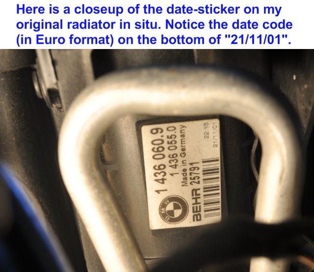
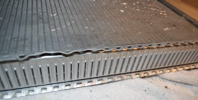
Lastly, I took a long hard look at the radiator metal itself. I was shocked at how clean and pristine looking the inner flat tubes appeared to the naked eye. They were amazingly clean, considering the car was built in late 2001 and 91K miles had been driven on this OEM radiator (date code verified).
In the future, an enterprising individual who comes up with a method for re-crimping new plastic (or better yet, aluminum) side panels, will be a very rich person!
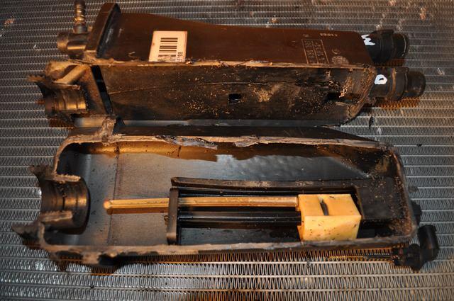
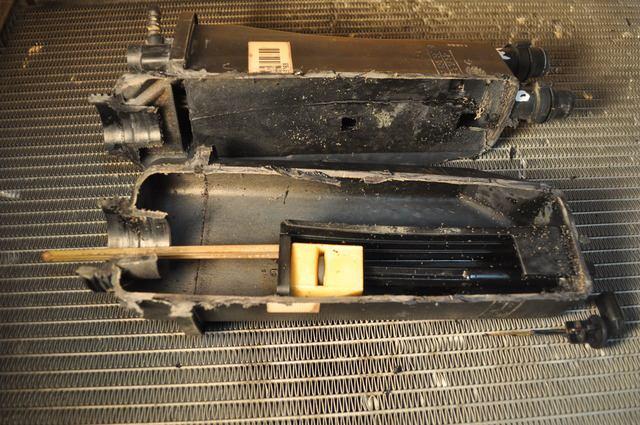
Expansion tank autopsy
Moving on to the expansion tank (aka surge tank) autopsy, it should be noted that I opted for a longitudinal autopsy because the only prior BMW E39 expansion tank autopsy I know of employed horizontal cuts. As such, that prior horizontal autopsy sliced directly into the level measurement pieces, complicating the analysis of the possible failure modes.
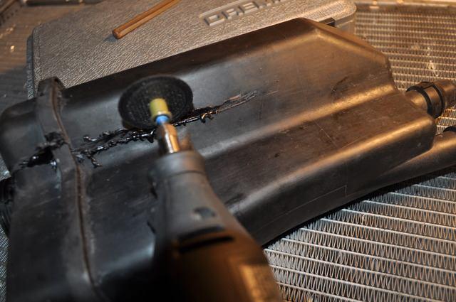
Vowing to not make the same mistake, and to further our knowledge, I bought a dremel tool and 200 dremel bits so that I could slice into the expansion tank without destroying the delicate level-sensing mechanism inside.
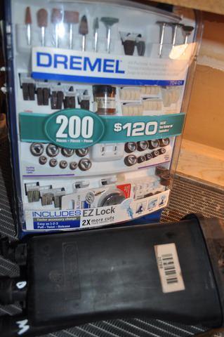
As luck would have it, I broke the only bits that cut into the expansion tank and had to return to the store to pick up just a set of the desired cutting tool.
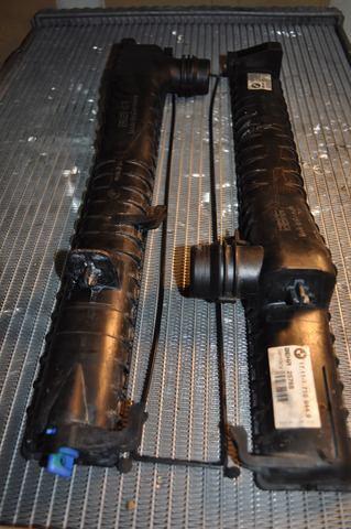
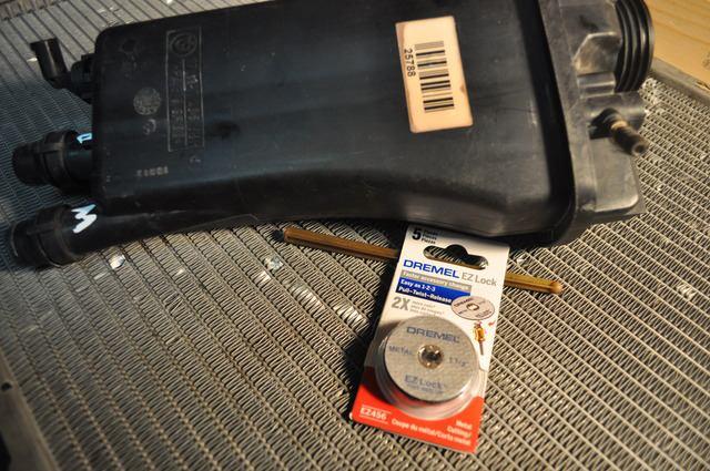
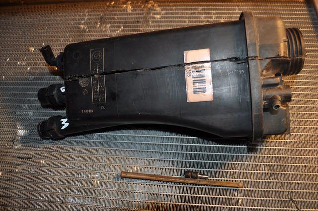
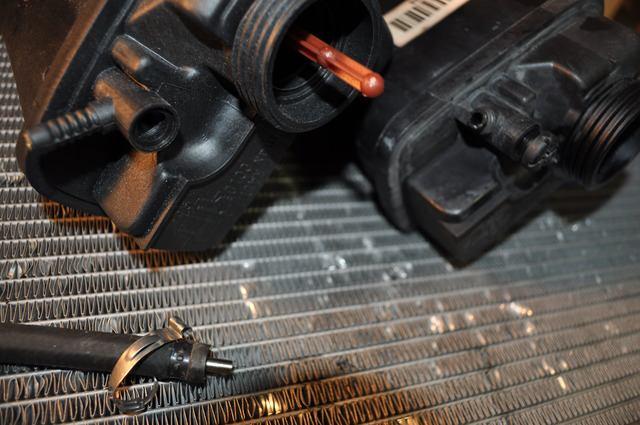
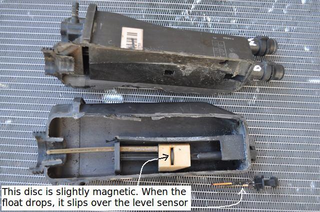
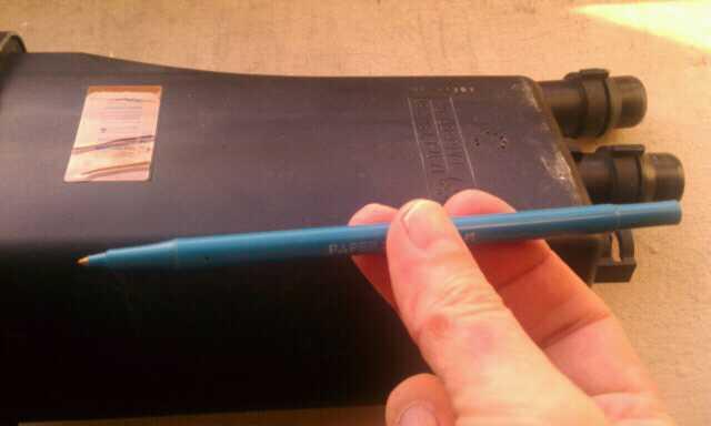
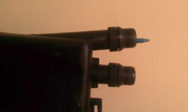
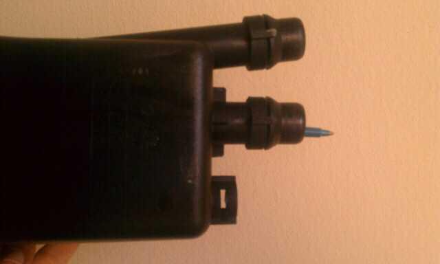
Note: The "D" and the "M" are the markings for the distal and medial tubes respectively (the hoses are similarly marked so as to avoid confusion in replacement).
I carefully measured by eye a longitudinal slit that would bisect the expansion tank without damaging the coolant level sensing mechanism within. The second set of dremel tool bits easily cut into the expansion tank along that desired line.
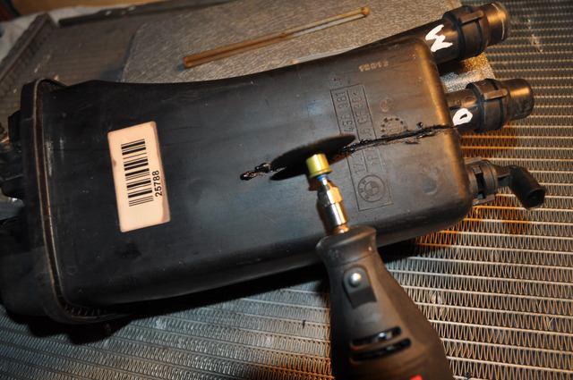
At some points the plastic was thicker than others and melting occurred, but that was of no major consequence. Notice, by the way, that the level sensing bobber stick is outside the expansion tank. This is due to a failure previously noted about six months ago in this thread:
- My radiator floating level indicator seems to be MIA (where does it go?)
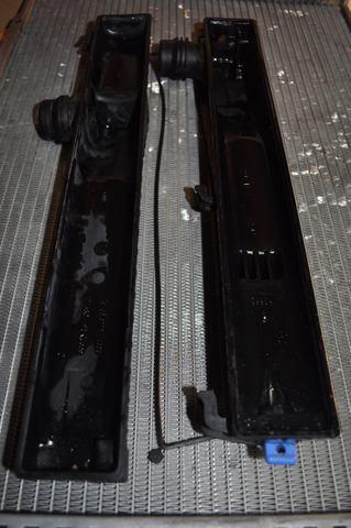
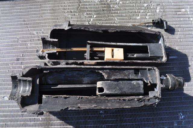
Soon I had the expansion tank longitudinally girdled. Notice the broken expansion tank nipple. Even though this Behr expansion tank nipple is reinforced with a tube of metal, this broke off when I removed the hose clamp from it in order to remove it from the car.
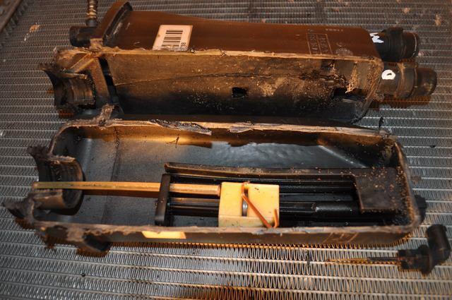
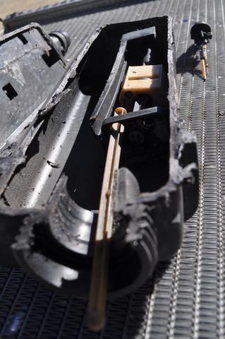
Once girdled, the expansion tank easily cracked open, revealing that I had cut it at the perfect junction of the inner bulkhead between the level-sensing compartment and the overflow relief compartment.
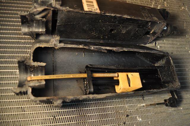
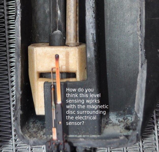
Placing the electrical sensor at approximately the position it would lie, I moved the float to the "full" position, with the broken-off bobber stick also placed in the correct OEM position on the side of the float.
It is important to notice the steel band of metal which I used to prove that the disc in the center of the float is slightly magnetic. It is clearly magnetic, but only slightly so. The white part of the float itself is made of a light plastic material and which is not magnetic.
Here I placed the float and bobber stick in approximately the coolant "empty" position. Notice that the magnetic disc now encircles the electrical sensor at the bottom of the expansion tank.
Here I've placed the float in the "too full" position. Notice also that there is an incomplete bulkhead on the other half of the expansion tank (much as was seen in the Titanic's six front watertight bulkheads which were only watertight horizontally, not vertically). At the moment, I surmise this thin plastic bulkhead (incomplete at the top) apparently separates the overflow operation of the expansion tank with the level-sensing operation.
In my tentative summary, I assume the following operational explanation (which I invite others to help flesh out in detail).
Surmised operation:
- The expansion tank has at least three different operations, namely visual level sensing, electrical level sensing, and overflow operation (if there are more, let me know).
- The electrical level sensing is apparently triggered when a float containing a slightly magnetic disc with a hole in the center, envelopes the tip of the electrical sensor. This apparently triggers the "low coolant" warning.
- That same float also contains a loosely glued on bobber stick, which indicates visually the coolant level. A typical failure is for that stick to disengage from its float. This disables visual level sensing; but it does not seem to have any effect on electrical sensing unless the stick itself causes the float to hang up in operation.
In practice, it is very difficult to remove an old expansion tank overflow hose clamp without breaking the nipple, even though that expansion tank nipple is metal reinforced against that happenstance. If you're going to remove the expansion tank hose, you may as well assume you're going to replace the expansion tank.
Originally Posted by agent15  This piece broke despite, as BB notes, the metal reinforcement tube inside the outer plastic connector. This design definitely belongs on the list of head-scratchers... |
I agree. My plastic nipple was so brittle that almost anything would have broken it off.
Because of that, and because people may wish to re-use an expansion tank if it's fairly new, it behooves us to come up with an OEM-hose-clamp-removal process that is the least forceful we can devise.
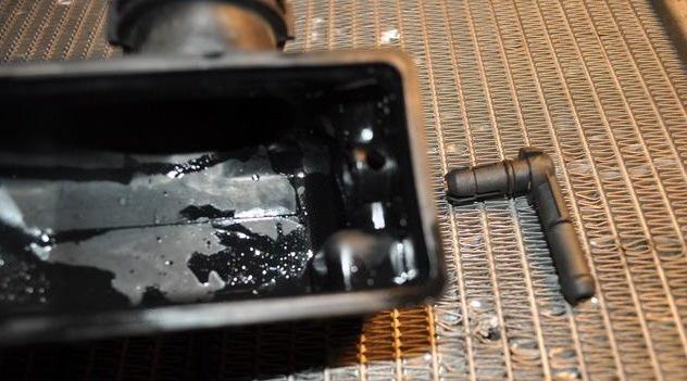
At first, I tried to "chop" off the crimped nub of the OEM hose clamp with snub-nosed wire cutters.
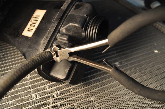
Almost instantly, as soon as a modicum of side force was applied, the nipple simply "twisted" off (it twisted because the plastic broke but the metal sleeve was still intact).
At this point, I realized I should have either dremeled off the hose clamp (so as to exert zero sidewise force) or I should have lifted up on the end of the hose clamp wrapped and locked end.
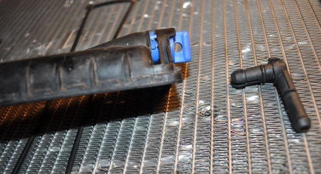
Here you see the pliers used to lift up on the end freeing successive lock pins in the OEM clamp. In hindsight, even this would have exerted too much sidewise force on the nipple, dooming it to failure.
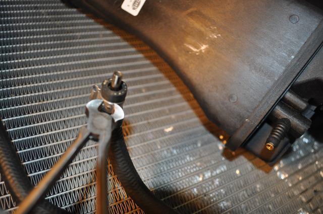
Finally the OEM hose clamp was "peeled off". In the future, I would dremel off the hose clamp. I welcome a BETTER method from the peanut gallery if you can propose one.
BTW, I do realize that it's almost futile to try to "save" the expansion tank if the nipple is as brittle as mine was. However, I can imagine a situation where you have to "go back in" after doing recent work - and then, you would have a less-brittle nipple (my assumption anyway) and you'd want to "save" the expansion tank if you could.
So, if anyone has a less damaging way to remove the hose clamp, let us know!
BB
I understand. I was just surprised how pristine my core radiator looked, and how flimsy the plastic was, and that the only thing in between was a little rubber gasket.
Just like with the headlight adjusters and abs control module, a little bit of non-BMW American ingenuity could outsmart the inherent built-in BMW material flaws.
So, I'm "suggesting" that a "fabricator" out there, might consider making the end plates out of aluminum, and they can then do a booming business "rebuilding" radiators by swapping out the plastic plates with aluminum ones.
Here's a picture of the side of the radiator core with the side plastic removed. There's only the crimp and a rubber gasket. That's it.
Originally Posted by 540iman  Steel band is likely a 400 series stainles steel. 300 series stainless, which is used for flatware, knives, pots and pans, etc. |
Hi Bill,
I think I may have confused the description a bit.
The copper-colored bent "steel band" that I picked up off a cardboard box (it was a steel staple in a refrigerator box) was just a piece of steel that I used to prove that the circular disc in the center of the white float was slightly magnetic.
Here's a picture of the float mechanism showing the magnetic disc about in the center of that float. That magnetic disc, when it settles over the tip of the coolant level sensor, magnetically triggers "something" somehow.
How do you think the level sensor works when triggered magnetically?
Quote:
| Originally Posted by 540iman My plastic bobber must have separated from the float |
For the record, Bill is referring to this:
- Check Coolant warning-float 2" above filler neck???
- Check coolant light, coolant is tad low, but "bobber is full up
11-30-2010
| Originally Posted by dms540i BMW should comp you a donor car just to drive around and do post mortems on their engineering flaws. |
Thanks.
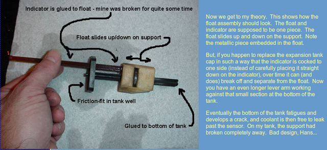
By way of post mortem, below are some pictures which show exactly the weak point in the coolant level visual indicator stick.
Many say it 'disintegrates' but it's pretty tough material. Everything inside the expansion tank is tough material. I doubt anything disintegrates.

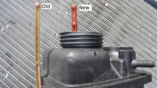
I think the weak point is where the stick attaches to the float. You can see in these pictures that it snapped clean off exactly at the top of the float.
In hind sight, I recommend folks be very gentle when they pour fluids into the expansion tank when the bobber stick is up so as not to tilt it. Notice the float itself doesn't have much (any?) side-to-side degrees of freedom.

NOTE: This picture above is re-used from a previous thread.
So, if you tilt the bobber stick, but if the float can't correspondingly tilt (because it's confined to a vertical track), then it seems to me that will break the bobber stick off at the weak connection point - which is exactly on top of the float.
One other thing to note is there are different styles of bobber sticks. I wonder if we can characterize them to tell whether an expansion tank has been replaced in lieu of date codes?
Of course, I use a rather obvious "date code" method when I replace parts:
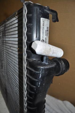
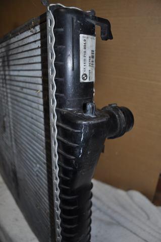
There's another oddity which can 'pinpoint' (intended) an OEM radiator, which I remember someone mentioning before but I couldn't find the thread.
Notice the OEM radiator has this white "pin" on about the 10th row from the bottom.
In the prior discussions (which I can't find), folks surmised this is some sort of 'date code' to the manufacturer.
What do you think its purpose is?
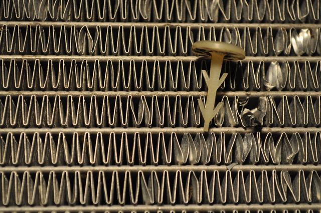
Can you make any sense of this?
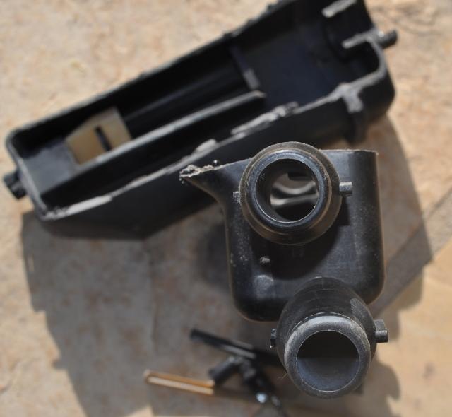
To further dig into the inner complexities of the expansion tank, I cut into that incomplete plastic bulkhead separating the expansion chamber from the measurement chamber.
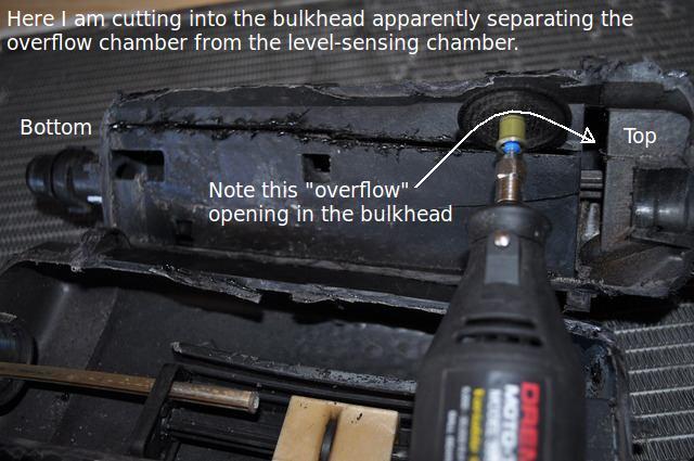
What was revealed confuses me.
Inside was a small rectangular fixed-in-place structure, directly above the distal bottom hose opening, whose purpose eludes me.

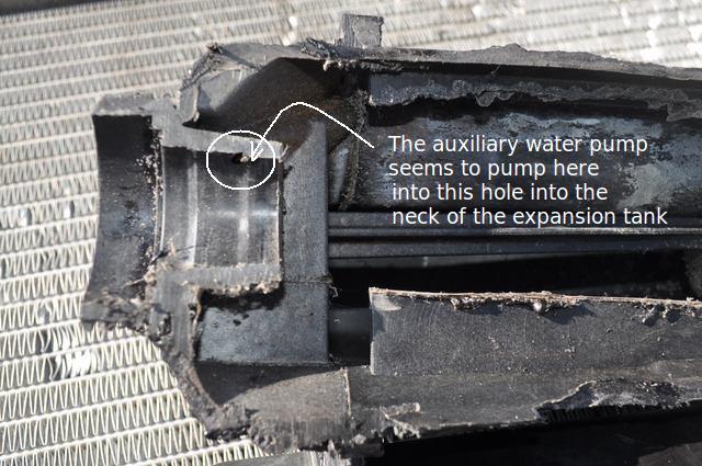
This box-like open structure over the distal hose is "pinned" down by a post coming down from the top of the surge tank; and this box has a hole in the top corner of it.

BTW, above all this, there is another hole in the upper neck of the expansion tank. This is where I see water flowing when the auxiliary water pump is running.
Can you make any sense of what the purpose and operation of these structures is?
12-2-2010
I found another failure mode for the expansion tank!
I can see the failure; but I do not know the implication.
It's a mystery to me, that can be resolved if someone helps us understand how this other half of the expansion tank actually works.
Please help explain what this does!
In this picture, you can see the thin incomplete bulkhead which hides the second failure point in my expansion tank.

Notice, behind the bulkhead, is an apparently MOVING part, which seems (perhaps) to slide up and down the incomplete stalk through a rather large hole in the apparatus' corner.
Mine was fixed in place, locked down, by the stalk being in the center and not at the hole. But what is the hole for, if not for the stalk.
And, why would this 'box' slide if it wasn't meant to slide, fitting perfectly in the inside contour of the expansion tank???
Also notice this chamber is fed by the auxiliary water pump ... which may hint at its purpose.
But, the main question, is what is the purpose of this chamber?
And, did it fail?
Notice, for example, the stalk is blocking upward motion of this box.
I think we'd need a third expansion tank autopsy to confirm or deny my hypothesis that this chamber failed in my expansion tank because the stalk moved out of the corner hole and blocked upward motion.
Please, the next person to replace their expansion tank, please cut it open and take care to note the position of the stalk and box in the hidden chamber behind the thin incomplete bulkhead.
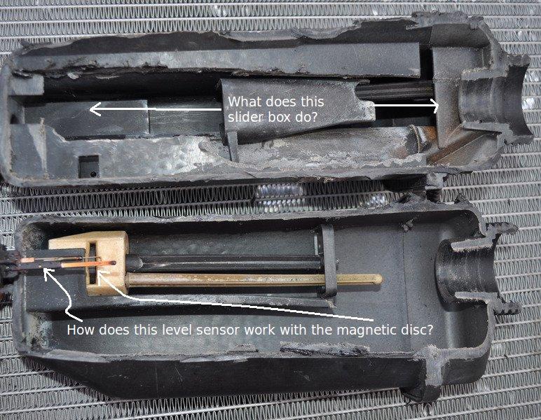
Do YOU have an idea about what this chamber is for and how it might work?
I realize I'm asking questions that have never been asked before, so perhaps that's why nobody has stepped forward with an answer as to what that separate floating black box does in the expansion tank, in practice.
Also, nobody has outlined what that failure mode could be indicating, now that my floating box was pinned stuck by the post.
Even with those unanswered enigmas, here's another challenge for our combined tribal knowledge of the cooling system.
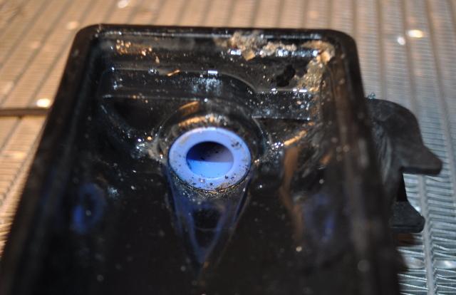
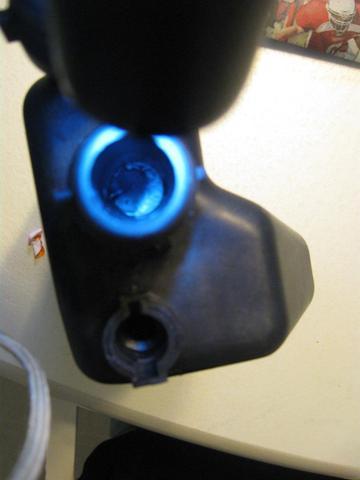
How do you think this electrical level sensor works anyway? Of course, the magnetic disc, when it surrounds the tip of the electrical level sensor, somehow triggers the low coolant warning; but how does it actually work?

Here's a closeup. I wonder what's in that tiny bulb on the stalk of the electrical level sensor.
I don't know how this triggers the low coolant light. Do you?
12-5-2010
After having uncrimped the radiator side panels, and having seen how pristine looking the inner tubes are, I'm positive the radiator could be rather easily rebuilt with the right equipment and side panels.
- You un-crimp
- You put on two new side panels with new rubber gaskets
- You re-crimp
- You test for leakage
As an xref, Spokane540ia who installed a Bosch radiator, will look up for us what the scoop is on rebuilding BMW E39 radiators.
12-8-2010
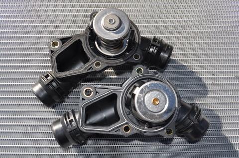
I haven't done the autopsy of the thermostat yet, but this reference from Rajaie of Beisan Systems details one way to test the thermostat operation:
"P1619 is a thermostat electrical code. Make sure the electrical cable connector is connected. You can try cleaning the connectors with electrical contact cleaner. There is a common problem with the thermostat where the heater circuit fails. You need to replace the thermoset for this. This failure can cause the heater circuit resistance to drop to 3 ohm and cause a 4A current to run through the cable wires. This can melt the wire insulation and cause the wires to short. Check the thermostat electrical cable wires just below the connector. Check ~3" of wire."
For more information on that ferstugenuh electric cable connected to the thermostat, see this mistakes-in-DIY thread:
- How bad is this mistake in putting my cooling system back together?
Originally Posted by gaplayer  you should consider writting repair manuals |
I'm currently out of a job - so - if any of the sponsors want to employ me to write DIYs for them - they should simply ask.
I'm willing to make their site the best on the planet for BMW DIYs if they only supply the car (if it's not my E39) and pay me by the article! 
| Originally Posted by gaplayer http://www.allradiator.com/ |
My radiator is replaced already, so, too late for me.
However, the NEXT person on a budget who needs to replace their radiator should look 'em up! Thanks for the pointer!
12-11-2010
Originally Posted by ross1  Hot enough to pull the headbolt threads from the block |
Ouch. There was a recent thread on that exact topic that you may be interested in (it was within the past week or two).
BTW, since nobody seems to know how that second hidden black-slider chamber works, and since mine was 'locked' into position (even though it appears to be designed to slide), I opened a new thread just to answer that one question in this thread:
12-30-2010
By way of easy linkable cross reference, this cn90 thread today seems to show that some people have a Behr manufacturing defect "flap" on the bottom expansion tank openings which is reputedly the cause of no cockpit heat when replacing the expansion tank.
- Anyone seen a defective Behr Reservoir before (2002 530i)
Cam references these threads:
- No heat condition caused by a faulty BEHR expansion tank
- Re: No heat condition caused by a faulty BEHR expansion tank
And, pleiades referenced a similar post here:
- What's the record for number of bleed attempts?
Apparently there is a bad batch of Behr expansion tanks with extra flaps in the bottom. So, when you buy a new one, check it with a flashlight. It should NOT have a flap AFAIK.
Looking up how the sensor works, I saw this description at
- BMW E39 Expansion Tank Failure Analysis
http://members.cox.net/rsm540i/E39ExpansionTank.htm
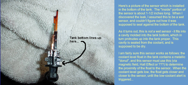
"I am fairly sure this sensor works as follows: the coolant level float in the tank contains a metallic "donut", and this sensor must use this (via magnetic field, Hall Effect or ???) to determine the proximity of the float to the sensor. When the coolant level gets low, the float gets closer and closer to the sensor, until the low-coolant alert is triggered..."
In case that members.cox.net article goes away, it's reproduced below. I tried to simply print it to a PDF file, but the file was 4MB which is 3MB too large for an attachment. So I just reproduced the screen shots to help others and for reference since he cut the tank open at a different angle than I did so what you see is another angle on the same theme.
Interestingly, he didn't go into any detail whatsoever of the second (hidden) chamber with the black float, nor does his picture show that entire section. Maybe it doesn't exist on the 540?
1-10-2011
Interestingly, today, cn90 over here pointed me to an old thread over here that explained how the (E46) coolant level sensor worked as shown below ...
In post #29, bidman explains:
"I am afraid Critter7r's 13 years in parts and service at 2 BMW dealers did not serve him well on this one. There is no such thing as a heating element in the coolant level sensor. There is no pocket of air for heating or cooling and no readings are taken, it is a simple magnetic float switch that operates around the outside of the tube in which the sensor sits. This is fitted to ALL the E46 models."
Later, in post #32, valvtronicdude explains further:
"The coolant [level] temp sensor is a magnetic switch. if you remove the sensor no coolant comes out right it's a dry sensor. there is a float inside the jug with a magnet in it. when the coolant level is low enough the float sits down over the glass bulb of the sensor and the magnet of the float causes two contacts to touch each other inside the sensor and cause a complete circuit. The instrument cluster sees this complete circuit and then knows the coolant level is low."
The last post gives the switch a name:
"To provide enough warning time for coolant loss, the sensor needs to be located part way up the tank rather than at the bottom of the tank. By the time the sensor contact gets made at the bottom of the tank, all coolant has drained out.
Also for those interested, the proper term for magnetically activated switch/sensor is call a Reed switch/sensor ."
1-11-2011
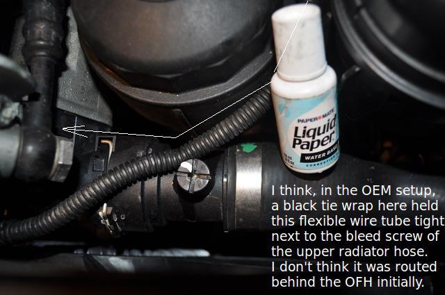
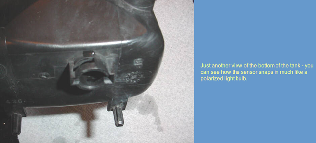
To better flesh out the cooling system autopsy record, even down to the little