You must be logged in to rate content!
47 minute read
DIY: BMW 650i / 645Ci / E63 / E64 Brake Pad and Rotors
Compliments of Yorgi @ bimmerfest.com
3-1-2011
Finally done! This turned out to be a much larger DIY than anticipated. I think I will create a "Readers Digest version" later for the more advanced DIY'er.
Yorgi's BMW 650i / 645Ci / E63 / E64 6 Series Brake Pad and Rotor Change DIY – with Pics
Disclaimer: The creator if this DIY is not a BMW technician. This article is provided freely for entertainment purposes only and does not come with any warranty of any kind. Use the information in this article entirely at your own risk. Always wear eye protection while working on any car. NEVER work under a car that is hoisted by a hydraulic jack only. Failure to use jack stands or to use wheel chocks could result in serious injury or death. Ensure the car is on a level and stable surface.
The creator of this DIY disclaims all responsibility and liability for the content or accuracy of information provided in this DIY. No rights can be derived from the content of this DIY. The creator of this DIY disclaims all liability for direct or indirect loss of whatever kind and on whatever basis, due to the use of information provided in this DIY.
NOTES:
Pictures below show a 2006 650i convertible. The procedure for a 645Ci, 550i, 545i, E9x M3, and E6x 7 Series should be relatively the same. Part numbers are based on information available at time of article creation. Check with your dealer to ensure the correct parts are used for your application.
I try to create instructions with enough detail for the first timer DIY'er. The experienced DIY'er can probably make do with the pictures and bolded text only. If this is your first brake pad change it should take about 2 hours, an experienced DIY'er can probably finish in less than 1 hour, including removal and re-install of wheels.
Rear parking brake shoe replacement is not covered in this DIY since I have never seen a car which required new brake shoes.
Some pictures below show the brake calipers removed from the car which was possible since I was also installing stainless steel brake lines. Do not remove calipers during brake pad changes or you will have to bleed the brakes after the pad install.
A. REQUIRED Supplies - pre-purchase from the dealer or online:
Prices below are full dealer list in USD; you can find parts online for approximately 33% less than full list.
Brake Pads
FRONT for E63/E64 - BMW Part # 34116794913 or 34116767191 ($159) (JURID pads)
REAR for E63/E64 – BMW Part # 34216768471 ($130) (Textar pads)
Brake pad wear sensors
The BMW TIS recommends replacing these during every brake job. You may break sensors on removal so it's a good idea to have a set on hand before you begin, even if you plan on re-using the sensors.
If your "BRAKE" light is lit on the instrument cluster you must replace the sensors.
FRONT LEFT - BMW Part# 34356789492 ($28)
REAR RIGHT - BMW Part# 34356789493 ($29)
NOTE for e9x cars (new 3 series) - you must install a new sensor if you wish to reset the Check Control mileage. After a reset with a slightly worn sensor the mileage will show as "------". You can temp install a new sensor, reset, then install the old sensor if you wish to reuse it.
BMW OEM Brake Pad Paste
BMW brand anti-squeal paste available at the dealer (great product) - Part # 81229407103 ($1)
Good alternatives:
GWR Ceramlub 2800 Purple
Permatex 24125 Ceramic Extreme Brake Lubricant
Brake cleaner spray
Copper or aluminum anti-seize paste
Good alternate brake pads:
See Yorgi's Brake Pad FAQ for aftermarket alternatives
NOTE: The E63/E64 use the exact same brake pads (front & rear) as the E92 M3. When searching for replacement pads you will find a much larger selection available if you search for E92 M3 pads. For whatever reason, most sites including Zeckhausen list a limited number of pads for the 6 series.
The front brake pad FMSI shape is D918 (HAWK pad shape is HB551)
The rear brake pad FMSI shape is D919 (HAWK pad shape is HB630)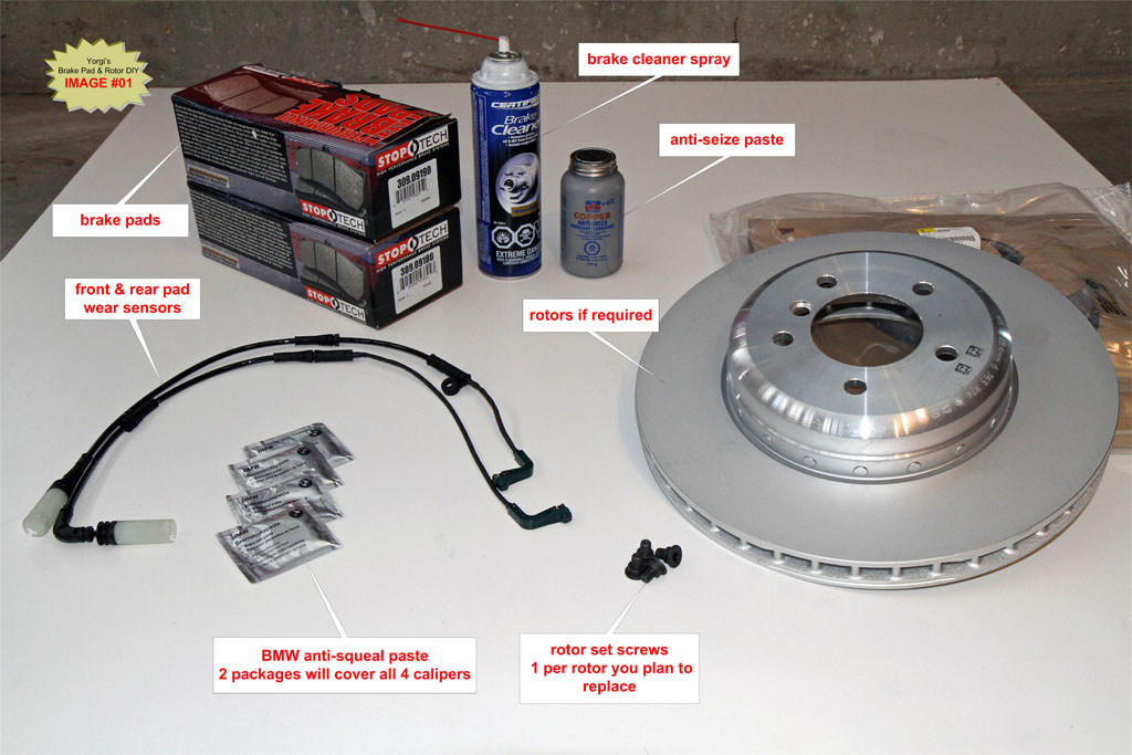
B. OPTIONAL Supplies – dependent on condition of existing components
Brake Rotors – If required – these are for 645Ci / 650i. 630i are different.
FRONT - BMW Part# 34116763824 ($180)
REAR - BMW Part# 34216763827 ($144)
Brake Rotor retention screws – 1 per rotor
BMW Part# 34211161806 ($1)
Brake Caliper Piston Repair Kit (if dust boots or pistons are damaged) - 1 per caliper
FRONT - BMW Part# 34111163647 ($25)
REAR - BMW Part# 34216753682 ($40)
Brake Caliper Guide Pins - Replace if damaged
FRONT UPPER (shorter) – BMW Part # 34111157041 ($20)
FRONT LOWER (longer) – BMW Part # 34116757036 ($21)
REAR x2 per caliper – BMW Part # 34111157041 ($20)
Brake Fluid – may be needed to top up reservoir after pad install.
You can use any DOT 4 fluid. Ate Typ200 is a good choice.
Jack Pad
Before ordering brake parts, check your car to ensure all 4 jack pads are still attached to the car. These tend to fall off. If you are missing jack pads order them along with the brake pads.
FRONT JACK PAD – BMW Part # 51718268885 ($15)
REAR JACK PAD – BMW Part # 51717039760 ($15)
C. REQUIRED Tools for Brake Pad Change:
Floor jack
17mm deep socket
7mm hex socket with extension (Allen head socket)
T25 Torx key for cabin air filter cover (removed for brake fluid reservoir access)
13mm socket for cabin air filter cover
8" or larger C-clamp
Large blade screwdriver or small pry bar
Small blade screwdriver
Coat hanger or other heavy wire - to hang caliper on spring while working on pads
Brake rotor vernier caliper. OR micrometer with a range of 1"- 2".
Trouble lamp
Half-round metal hand file
Torque wrench capable of 88 lb-ft, 22 lb-ft and 12 lb-ft
Ratchet wrench for sockets
Rags / shop towels
Wheel chocks
Wire brushes for cleaning calipers and carriers
D. ADDITIONAL REQUIRED Tools for Rotors:
18mm socket – required if changing rotors
6mm hex socket (Allen head socket) – required if changing rotors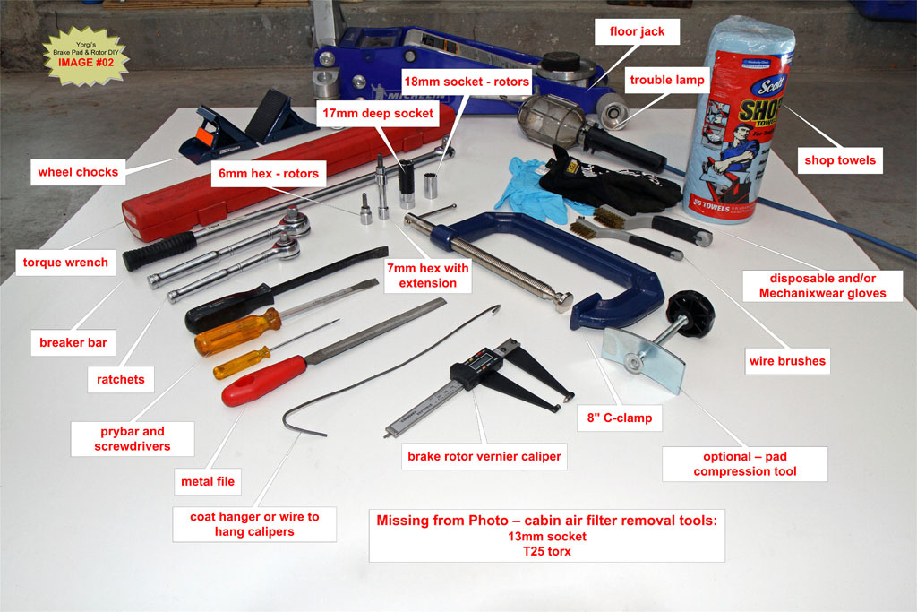
E. OPTIONAL Tools:
Mechanix Wear type gloves or disposable nitrile gloves
Impact drill or "cross wrench" for quick removal and install of wheel bolts
Disposable face mask filter to prevent inhalation of brake pad dust during cleaning of caliper
Rubber mallet to remove sticking rotors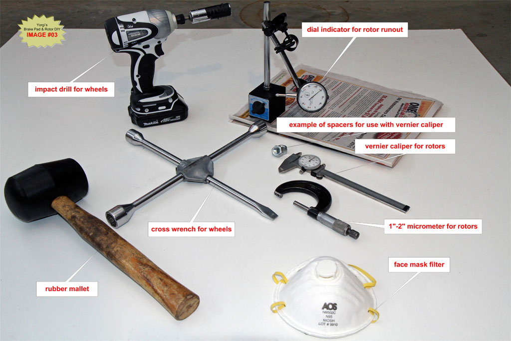
Tightening Torques – From the BMW TIS:
Wheel bolts: 120 Nm +/- 10 Nm (88 lb-ft +/- 7 lb-ft)
Caliper Carrier bolts: 110 Nm (81 lb-ft)
Guide Pins: 30 Nm (22 lb-ft)
Rotor set screw/retaining bolt: 16 Nm (12 lb-ft)
F. Before you begin:
Please be aware that mistakes made during brake pad replacement can result in catastrophic failure of the brakes. If you do not feel comfortable that you have the skills required to perform the steps below please leave your brake repairs to a qualified mechanic. Do not skip steps below that involve checking the condition of parts (rotors, sensors, guide pins). Failure to replace worn parts cold result in the failure of the braking system.
TIP: It is a good idea to pull one front wheel and one rear wheel to measure rotor thickness before you order new brake pads. This will allow you to add rotors to your order if necessary so you can complete both pads and rotors replacement at the same time. Also check your 4 jack pads to ensure none are missing.
G. Front Brake Pad Change Steps:
G1. Remove front driver side wheel
While the car is still on the ground, use a breaker bar with a 17mm extended socket to loosen the 5 wheel bolts. Break the bolt loose using a star pattern then gently re-tighten to the point where the bolt can still be removed once the wheel is off the ground.
If you have wheel locks and don’t know where the key is, check under the trunk mat where the battery and tools are located which is the standard storage location.
TIP: Cover the socket with black tape to prevent marring the wheels.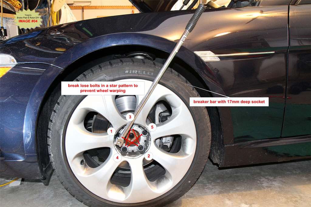
Engage the parking brake and chock the rear wheel on the opposite side of the car you are jacking to prevent the car from moving while on the jack.
Raise the front wheel using a hydraulic jack on the front left jacking point. See IMAGE #05.
Use a “cross wrench” or cordless impact wrench to fully remove the 5 wheel bolts. If the wheel is stuck to the hub after removing the 5 bolts, use a rubber mallet to hit the outer edges of the wheel until it comes loose. You can also sit in front of the wheel and use the heel of a running shoe to kick the outer edges of the tire until the wheel come loose.
TIP: During removal of the last bolt, press the wheel against the hub to prevent it from falling off the hub. You don’t want the wheel falling and hitting the brake caliper on the way down.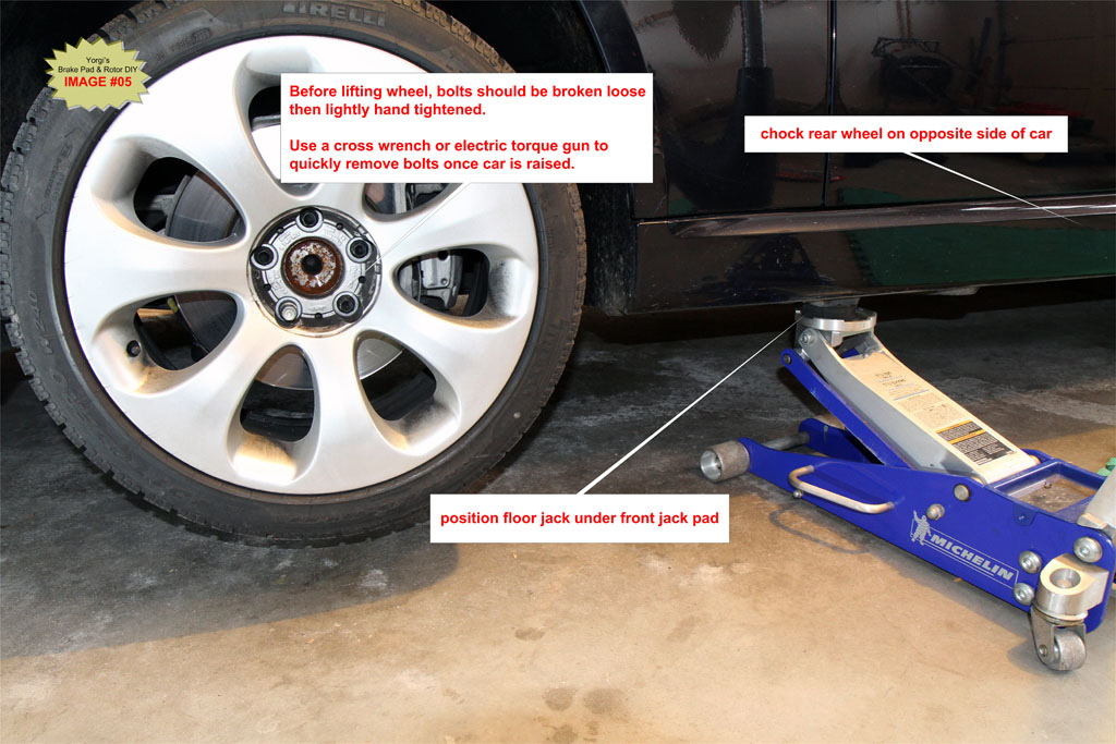
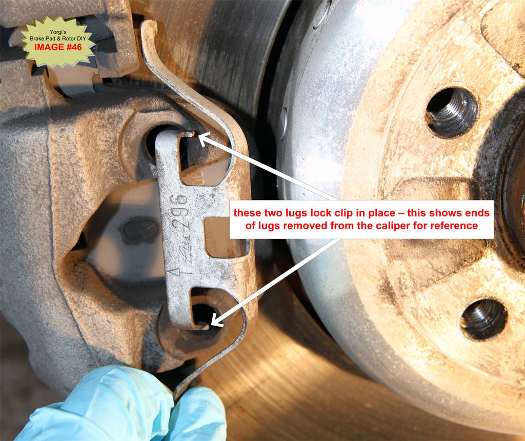
G2. Remove Spring Clip
Use a large blade screwdriver or small pry bar to remove spring clip from caliper. Pry the middle of the clip horizontally back towards the rear of the car until the retaining lug in the middle of the clip is exposed, then pull the clip towards you. 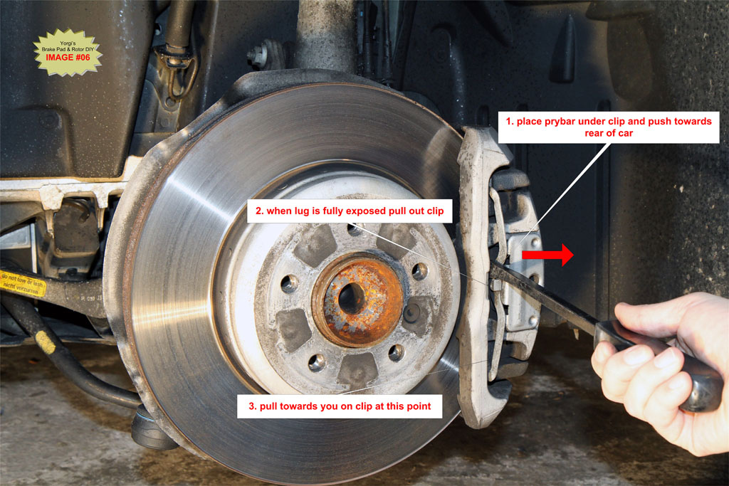
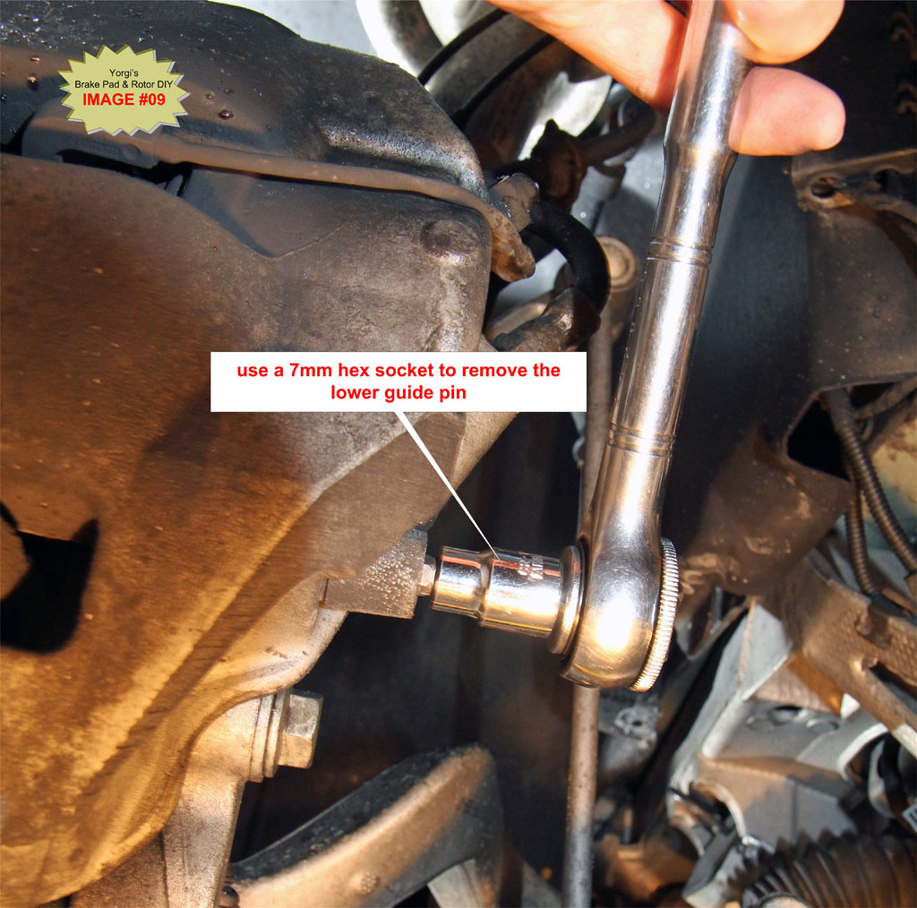
G3. Remove Guide Pins
Pry off the two plastic caps covering the guide pins. See IMAGE #7.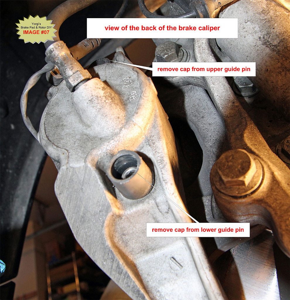
Using a 7mm hex socket, remove the upper and lower guide pins.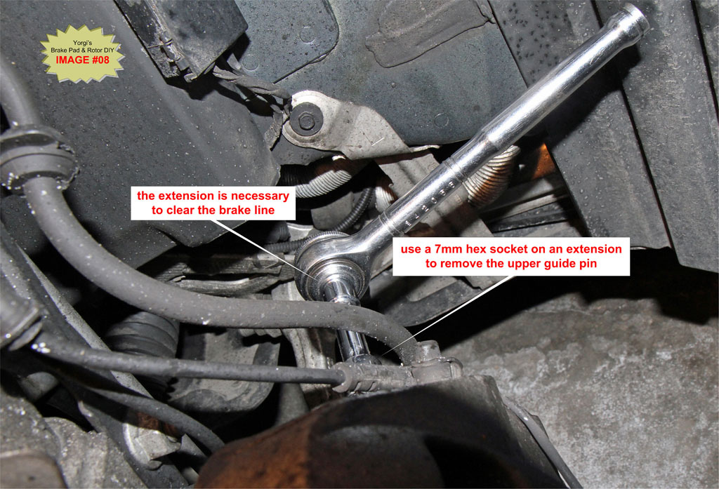
G4. Compress Piston back into Caliper
The piston must be fully pushed back into the caliper to make room for the thicker replacement pads. You also need to push the piston in to get the caliper off the carrier if there is a wear lip on the outer edge of the rotor.
Place an 8” C-clamp as illustrated in IMAGE #10. Be careful not to pinch wires or the bleed valve at the back of the caliper. Tighten the clamp until the piston is fully seated in the caliper. There should be only mild resistance as you tighten the clamp, if not check the positioning of the C-clamp.
TIP: Keep an eye on the brake fluid reservoir for fluid levels before and after each piston is compressed. If the fluid level rises to near overflow remove some fluid from the reservoir. Brake fluid is an excellent paint stripper and will severely damage paint if spilled. See Section J below for details on how to gain access to the brake fluid reservoir; it’s buried under the cabin air filter.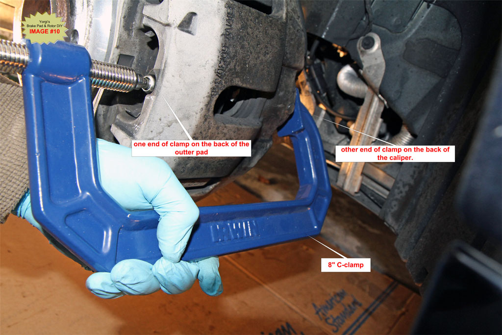
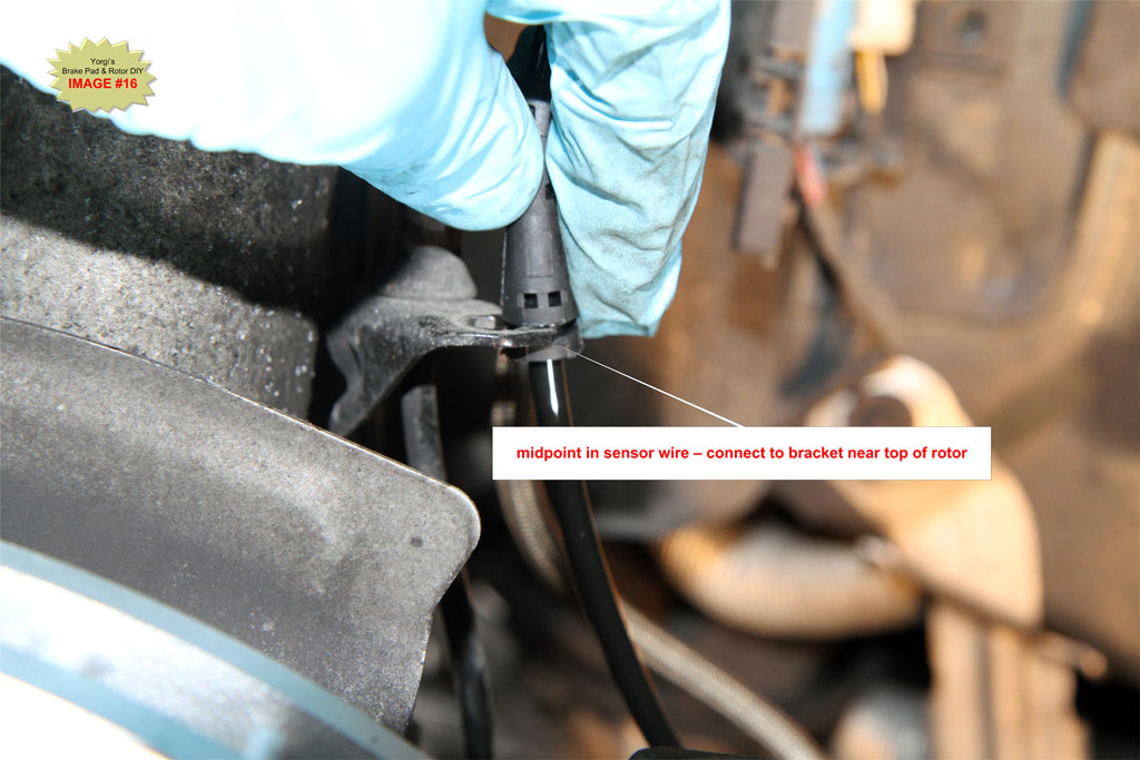
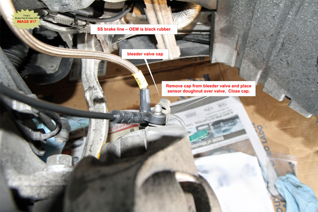
G5. Disconnect Brake Pad Wear Sensor (Front Left and Rear Right wheels only)
BMW TIS Note:
The brake pad wear sensor must be replaced once it has been removed (brake pad wear sensor loses its retention capability in the brake pad)
If you are a die-hard believer in BMW’s TIS recommendations, then always replace sensors when doing brake pads.
I examine the sensor for wear and if it’s in good condition I reuse it. It is still a very good idea to have new sensors on hand in case you break them during removal. They can get brittle over time.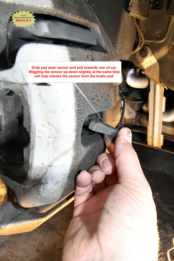
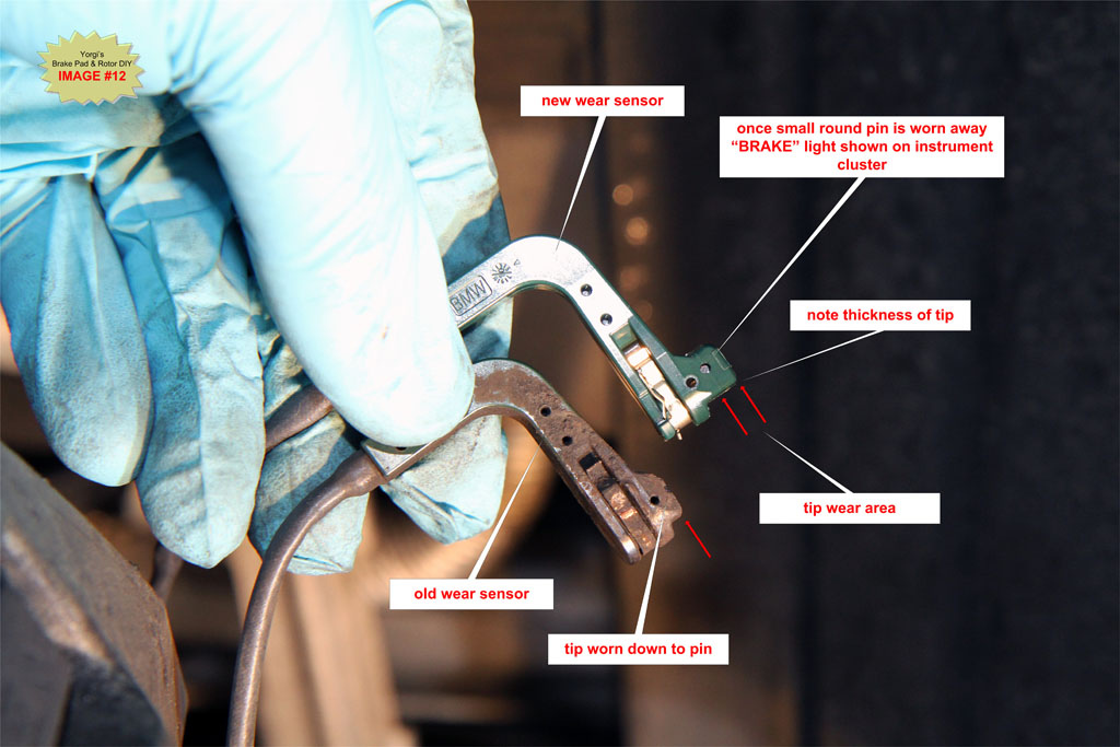
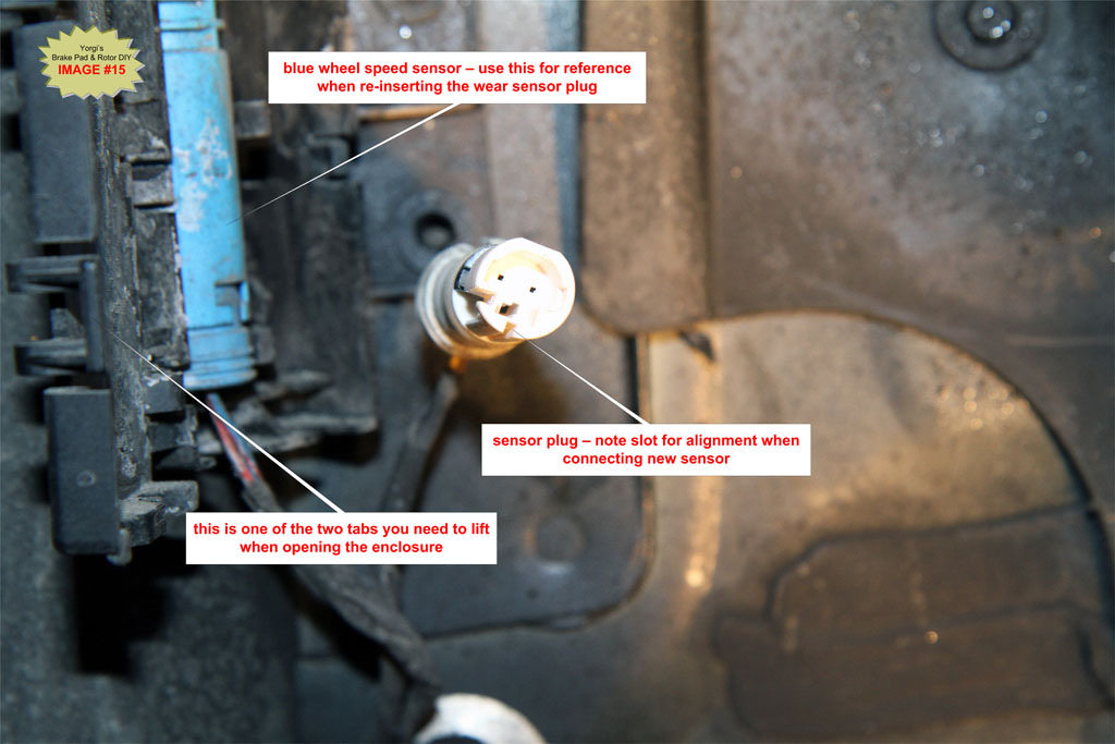
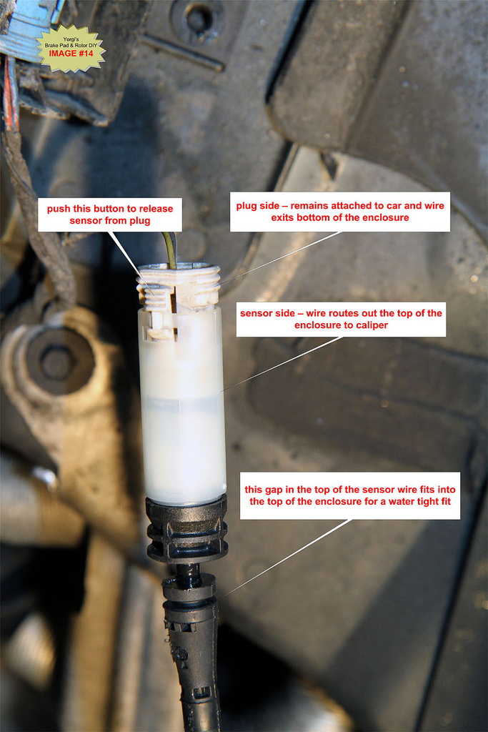
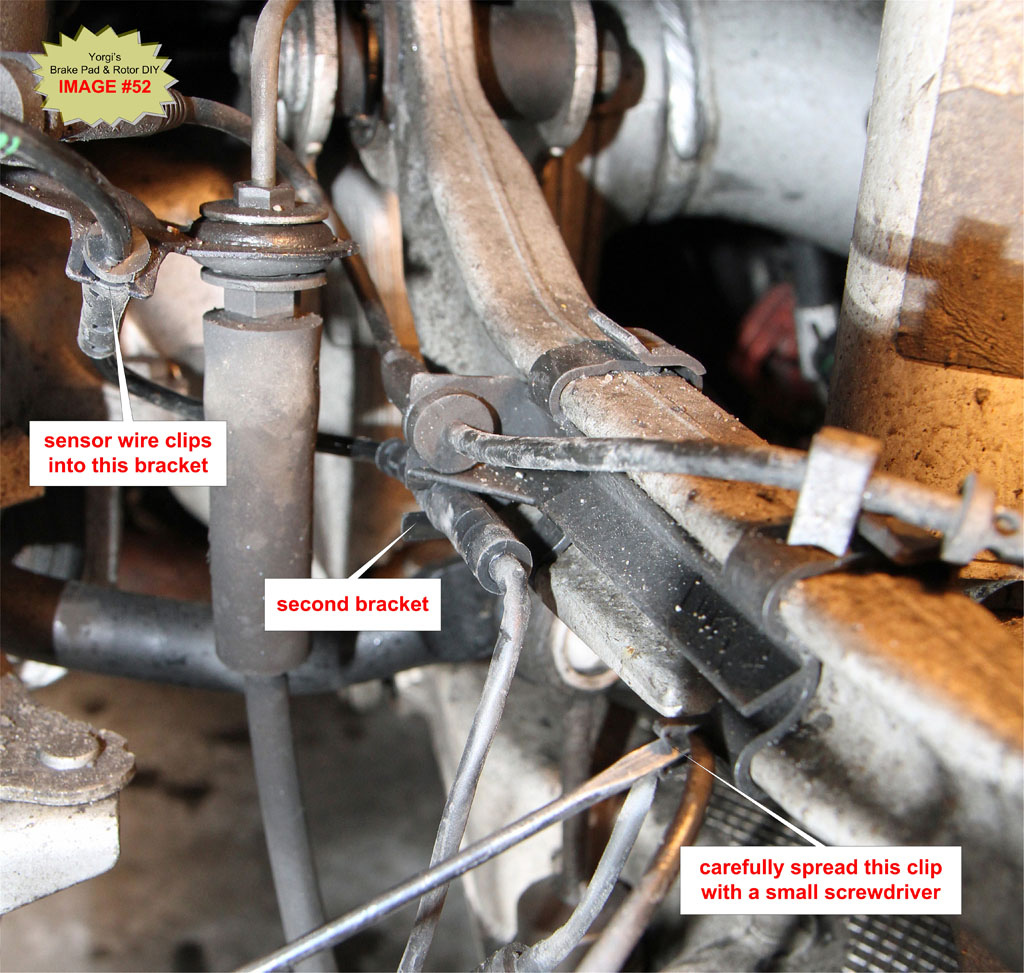
Follow the sensor wire back to the enclosure. Open cover of housing and unplug old sensor and replace with new sensor. There is a small push button at the base of the plug that must be pushed to release the plug. Use the old sensor wire to route the new wire back to the caliper. Do not install the “green” end of the sensor into the pad at this point.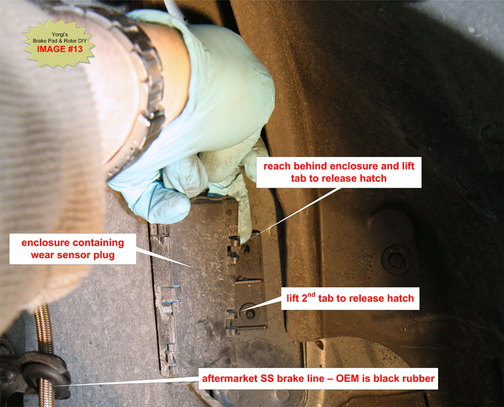
G6. Remove Brake Caliper from the Brake Carrier and hang it from the suspension spring
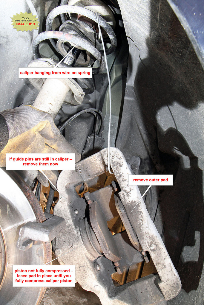
Wiggle the caliper off the carrier by pulling towards the back of the car. Never let the caliper hang by the brake line - you could damage the lines which may result in bake failure. See IMAGE #19for an example of how to hang the caliper by the suspension spring. You can also place the caliper on an upside down bucket or other suitable stand.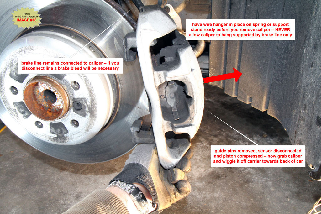
If the caliper does not come off easily the piston is probably not fully retracted. Repeat Step G4 to ensure the piston is compressed.
G7. Fully compress piston back into caliper if necessary
Once the caliper has been removed look at the piston and confirm it is fully compressed. If not use the C-clamp to push on the inner brake pad until the piston is fully retracted. To prevent damaging the piston, NEVER push directly on the face of the piston, always use an old pad or even a block of wood between the clamp and piston face.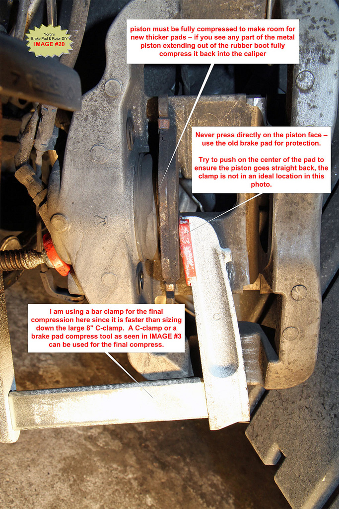
G8. Clean brake carrier, caliper and guide pins. Inspect condition of piston rubber boot.
Remove both brake pads from the caliper.
Examine the condition of the rubber boot and piston face. If any rips are visible in the rubber or if the piston face contains heavy gouges or a large amount of rust order a caliper rebuild kit from BMW. It is important to thoroughly clean the surface of the piston and the inside of the caliper directly across from the piston. These two areas contact the backs of the pads and if they are not clean and smooth brake squeal can occur.
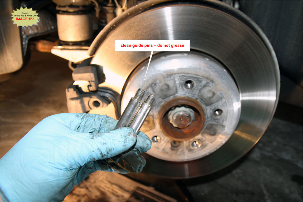
Guide pins should always be removed and thoroughly cleaned to ensure smooth operation of the caliper. The caliper slides on these pins and will bind if they are overly dirty resulting in rapid pad wear and possibly squeal.
DO NOT grease the guide pins. Unlike other cars which have metal-on-metal pins BMW uses a rubber-on-metal design that will bind the calipers if grease is used on the pins.
BMW TIS Note:
Replace guide screws which are not in perfect condition.
If you cannot get the pins clean or if you notice groves in the pins once they are cleaned replace the pins, they are not expensive.
Cleaning guide pins and the caliper-to-pad contact areas is dirty work but failure to do this will contribute to the likelihood of brake squeal and rapid pad wear. Dirty and binding calipers are a major cause of squealing.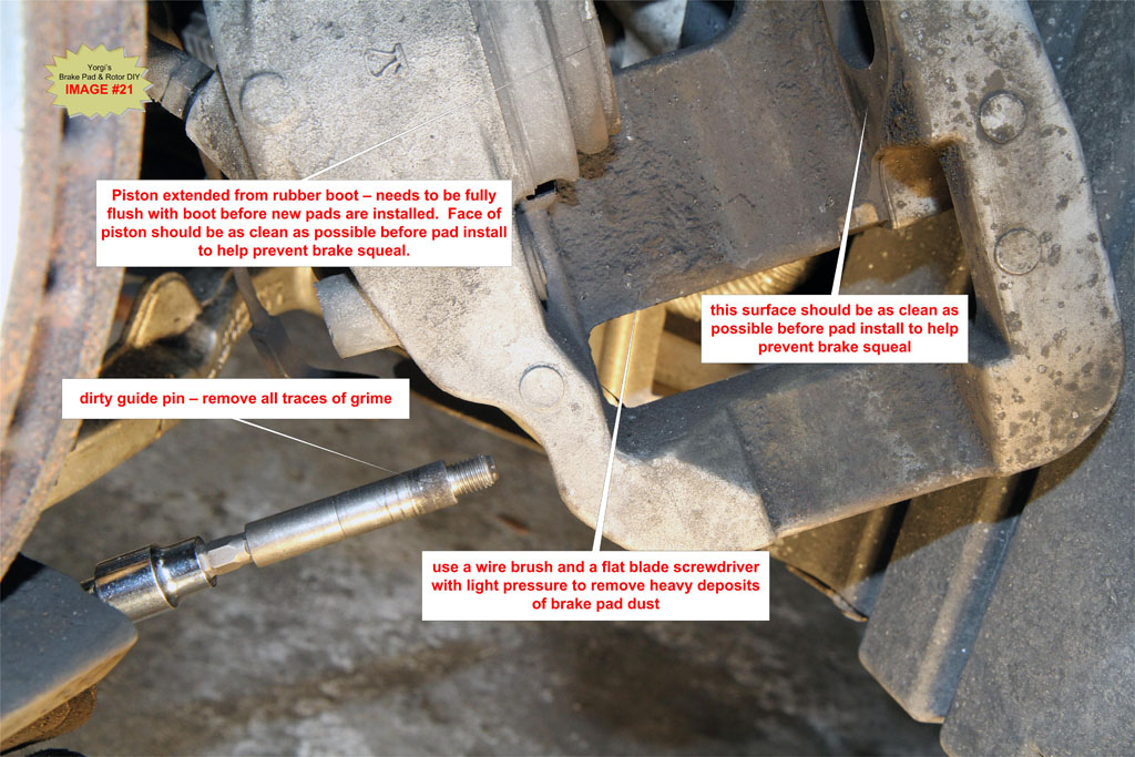
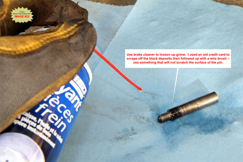
TIP: Use brake cleaner, wire brushes and an old credit card to scrape off deposits on guide pins.
I use small brass brushes to clean the caliper-to-pad contact points thoroughly. A small blade screwdriver can be used with light pressure to scrape off large deposits. Spray brake cleaner fluid liberally as you go. See IMAGE #21 and IMAGE #23 for a before/dirty and after/clean caliper and pins.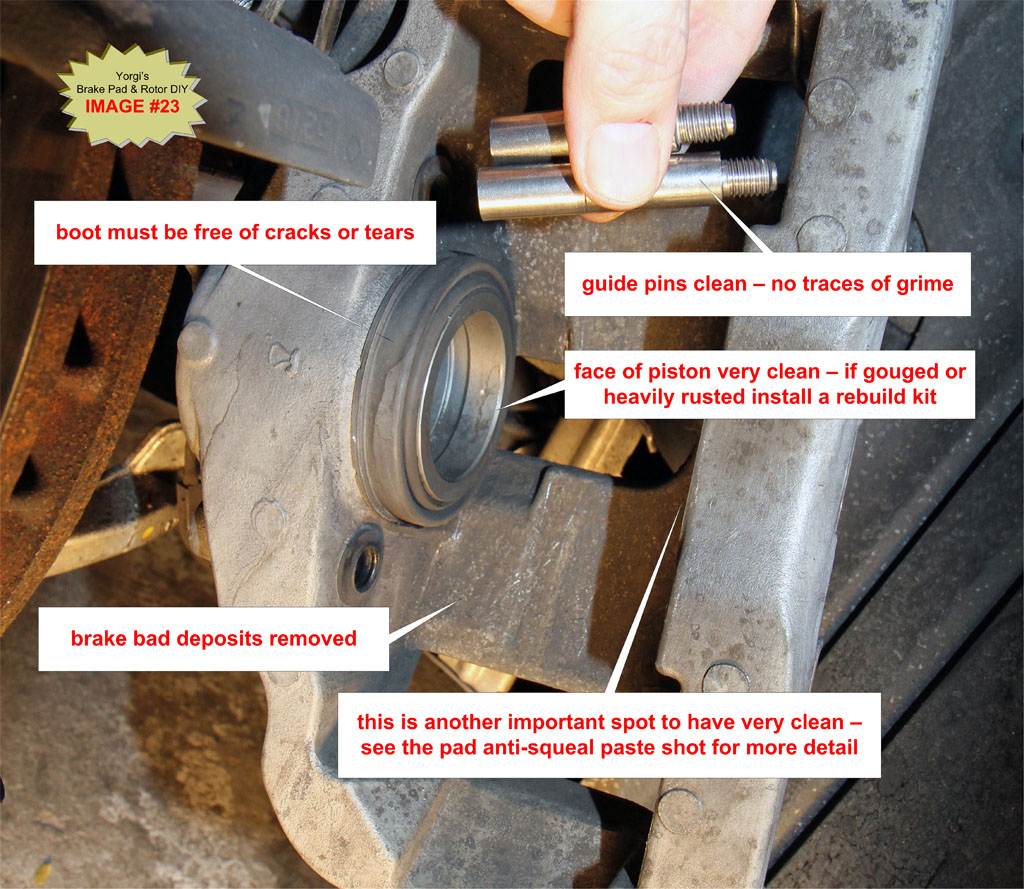
TIP: Place newspaper under the caliper to catch brake pad dust/grime that falls during cleaning. It is also a good idea to wear a face mask and eye protection while cleaning the calipers since quite a bit of dust can be kicked up if the calipers are very dirty.
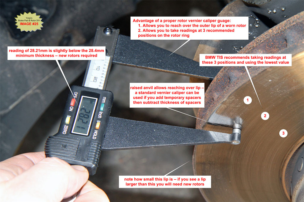
G9. Check Brake Rotor thickness and runout
The minimum allowable rotor thickness is stamped on the rotor hat. See IMAGE #24
Use a brake rotor vernier caliper (available on eBay for $30) to measure rotor thickness. A brake rotor vernier caliper will reach over any outer lip caused by worn rotors. You can also use a micrometer with a 1”-2” range to measure rotor thickness. As a workaround you can use a standard vernier caliper with two spacers placed on each face of the rotor then subtract the thickness of the spacers to get your reading.
If the rotor is below the stamped minimum then the rotors must be replaced. See Step G10.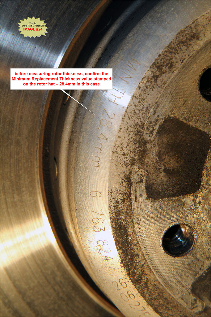
OPTIONAL: measure rotor runout
In addition to thickness, rotors can be checked for runout (warpage). A dial indicator with magnetic stand can be found on eBay for ~ $40. Large steel surfaces are rare on the 6er, so I used the carrier for the magnetic base. A stand with a clamp vs a magnet base might be preferable.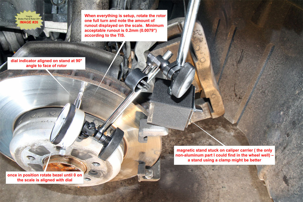
G10. OPTIONAL – Replace Brake Rotors If Necessary
Replace brake rotors if thickness is found to be below the minimum thickness stamped on the rotor hat. Always replace rotors in pairs.
Remove the two caliper carrier bolts using an 18mm socket or 18mm wrench and remove carrier from steering knuckle.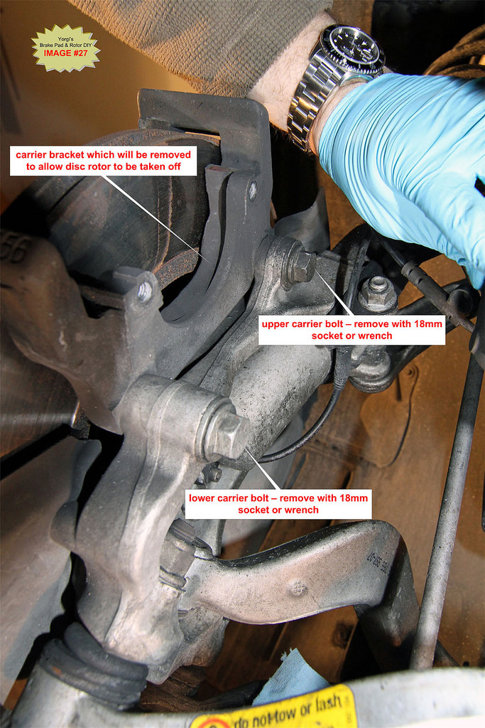
TIP: If you are removing the carriers for a rotor install, clean and lube carriers while they are off the car.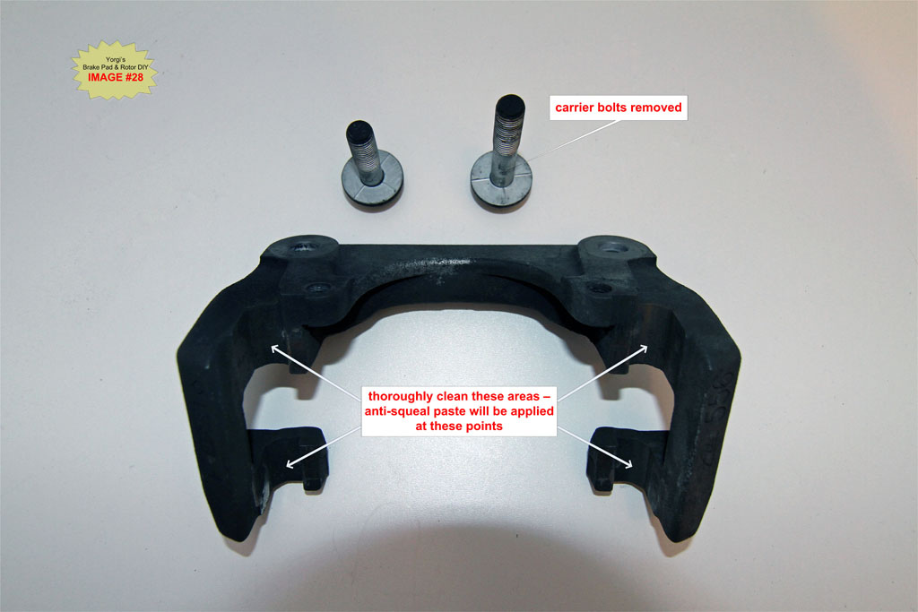
Remove rotor retaining screw from rotor with a 6mm hex socket. Keep pressure on the rotor with one hand to prevent it from falling off the hub while loosening the screw.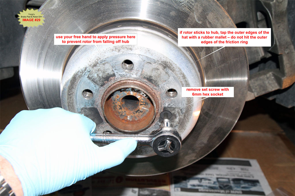
Pull rotor off hub. If it sticks use a rubber mallet on the rotor hat to loosen the caliper. Don’t hit the rotor ring with the rubber mallet.
Clean the face of the hub with a wire brush. Debris on the face of the hub can cause wheel vibrations or a warped rotor feeling when braking.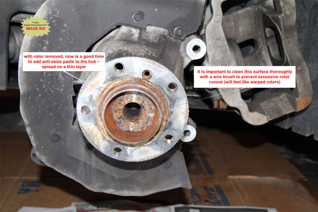
If retaining screw is rusty replace it. Seized rotor retaining screws are a common problem and will require drilling out if they get bad. If I see any rust at all on the retaining screw I replace them. At $1 it is cheap insurance against seized screws.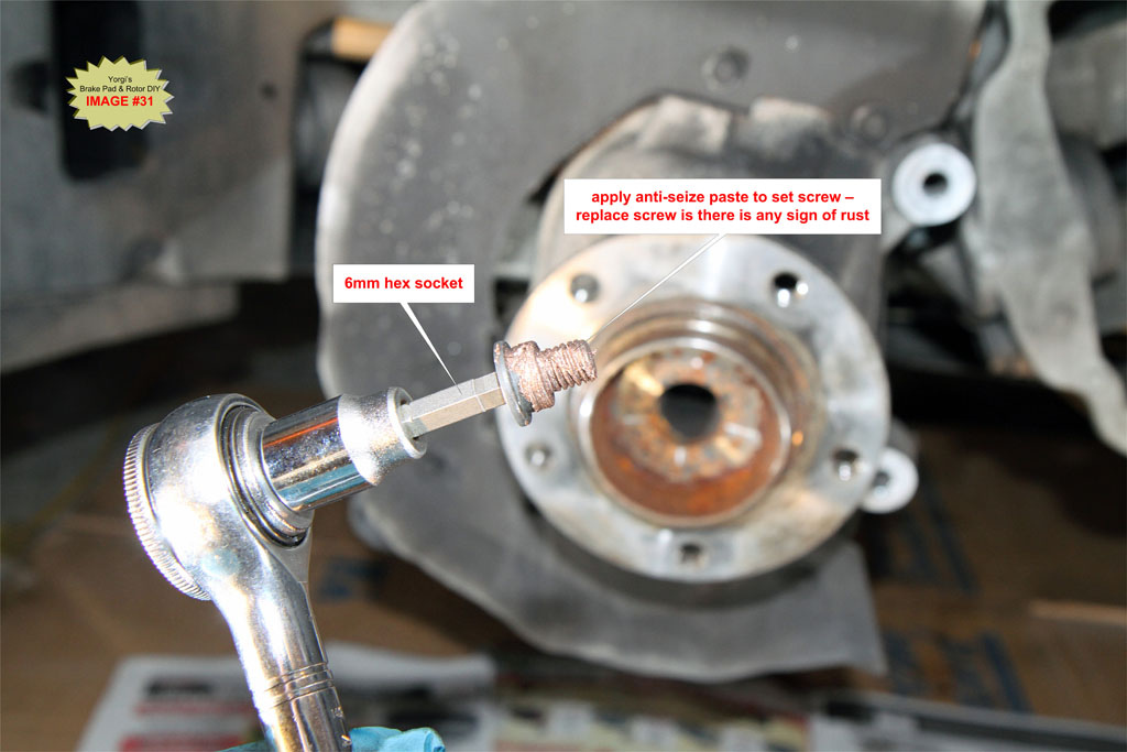
Install new rotor on hub. Use anti-seize compound on retaining screw threads and torque to 16 Nm (12 lb-ft).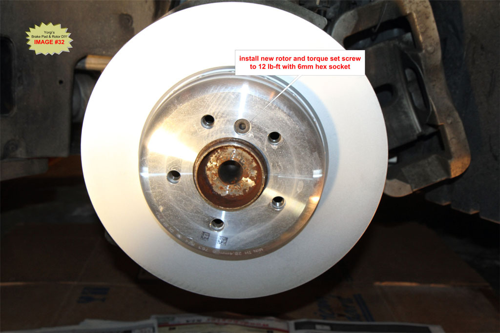
Install caliper carrier and torque bolts to 110 Nm (81 lb-ft).
TIP: If you are using anti-squeal paste on calipers, see IMAGE #38 and apply paste now before installing the carrier.
G11. Prep Brake pads for installation
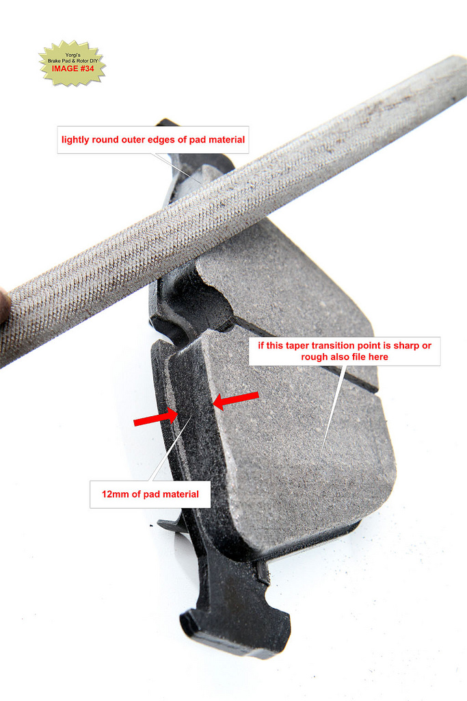
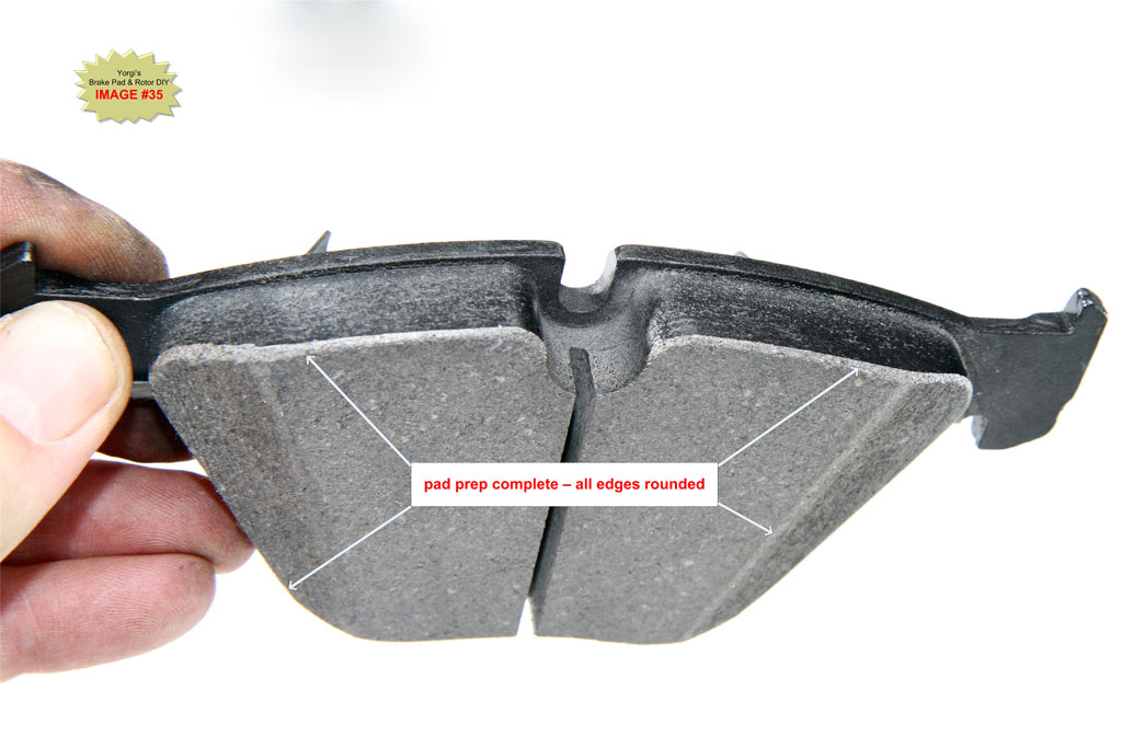
OPTIONAL: To help prevent squeal use a metal file to gently round the outer edges of the pads. This helps prevent pad vibration due to sharp leading edges coming in contact with the rotor. No need to take a large amount of material off, just gently round the edges. See IMAGE #35.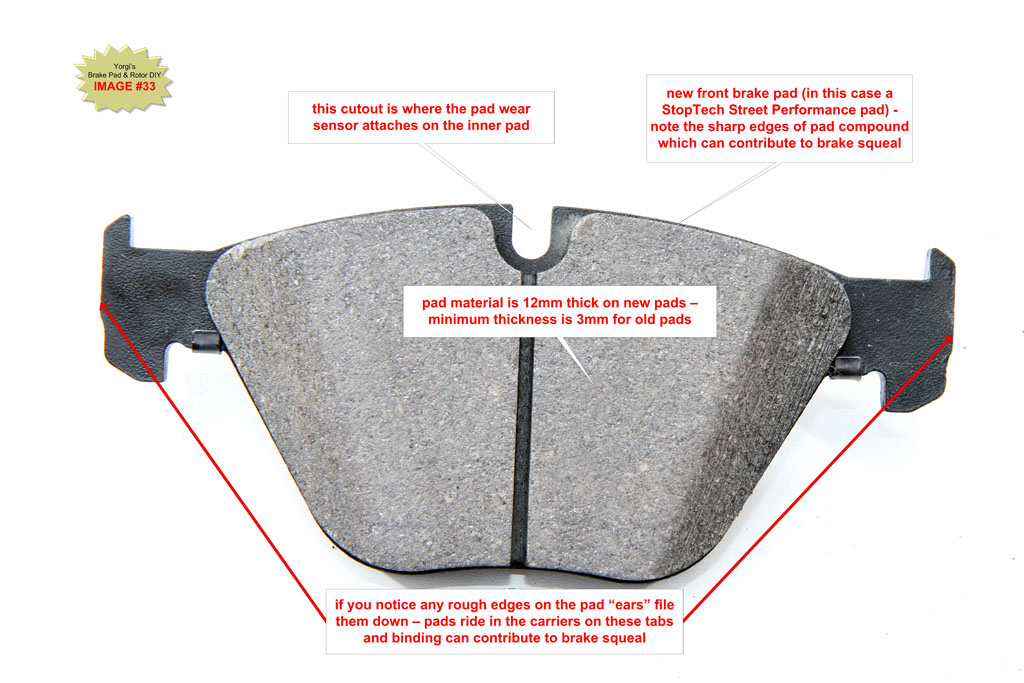
G12. Apply Anti-Squeal Compound to Caliper and Carrier
Apply a thin coat of anti-squeal compound to the piston surface being careful not to get any on the rubber seal which can cause swelling.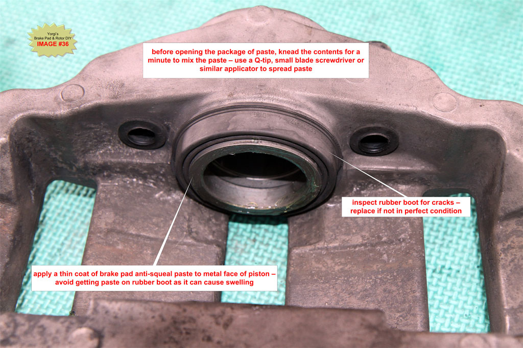
Apply a thin coat of anti-squeal compound to the smooth surface directly across from piston (where the back of the outside pad comes into contact with the caliper) and to the caliper hammer heads - where the outer pad ears will make contact. 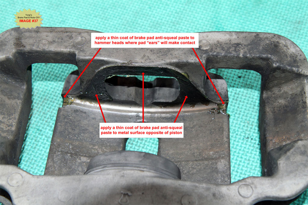
Apply a thin coat of anti-squeal compound to the caliper carrier at the pad contact points. Avoid getting paste on rotor. If grease gets on rotor, use brake cleaning spray to clean rotor.
TIP: If carriers were not removed for new rotor install, use masking tape to protect rotor from grease.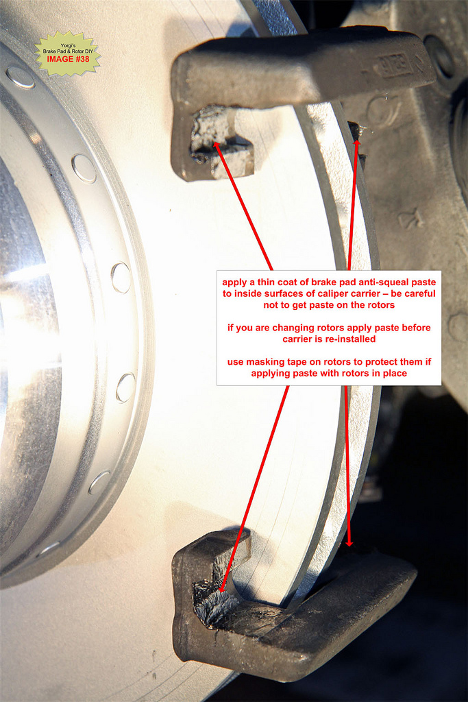
G13. Install brake pads and caliper
Push the inner pad, the one with 3 fingers on the back of the pad, into the piston. Push on the outer pad, with 2 fingers, onto the other side of the caliper.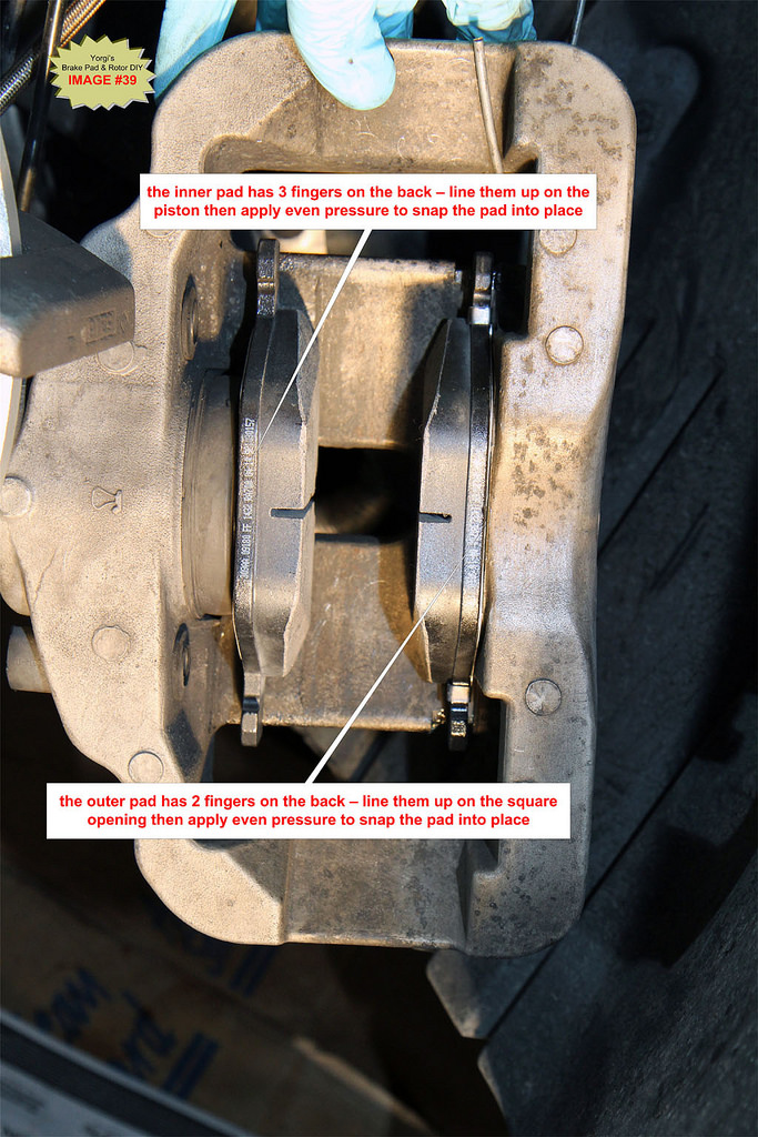
With the new pads installed, push the caliper back onto the caliper carrier.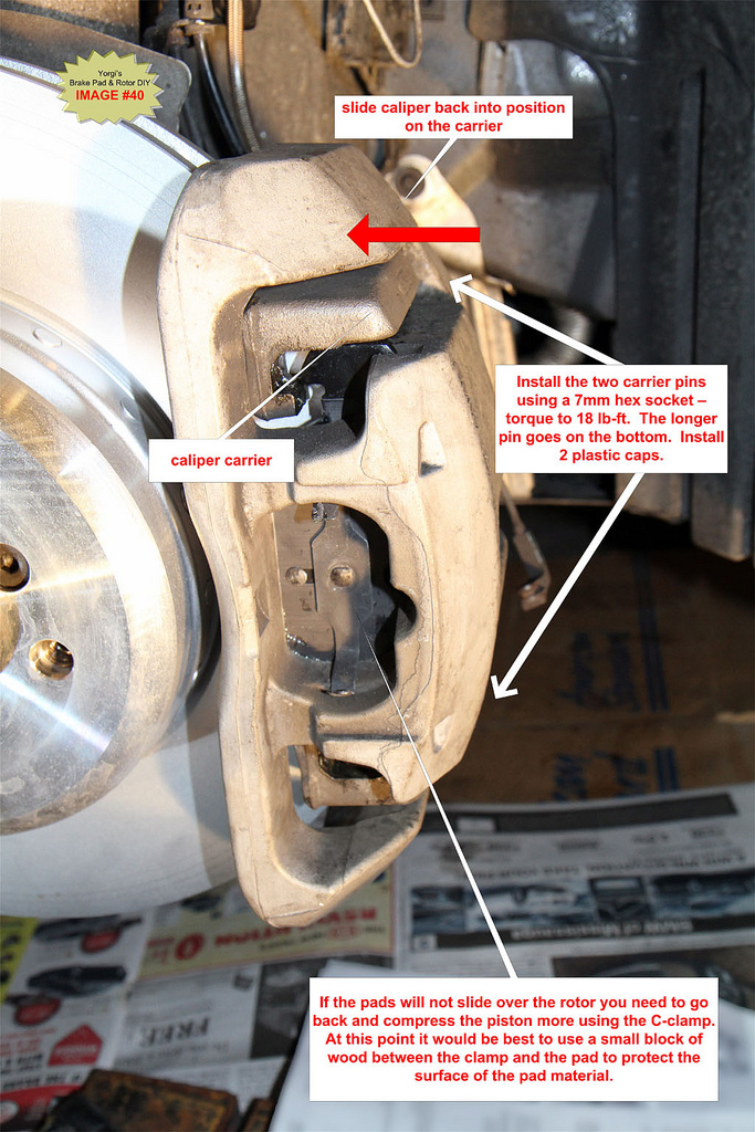
G14. Install Guide Pins and caps
Torque to 30Nm (22 lb-ft). Do not over tighten the guide pins and ensure they are clean before installing. Install the 2 plastic cover caps.
NOTE: the longer pin goes on the bottom of the caliper.
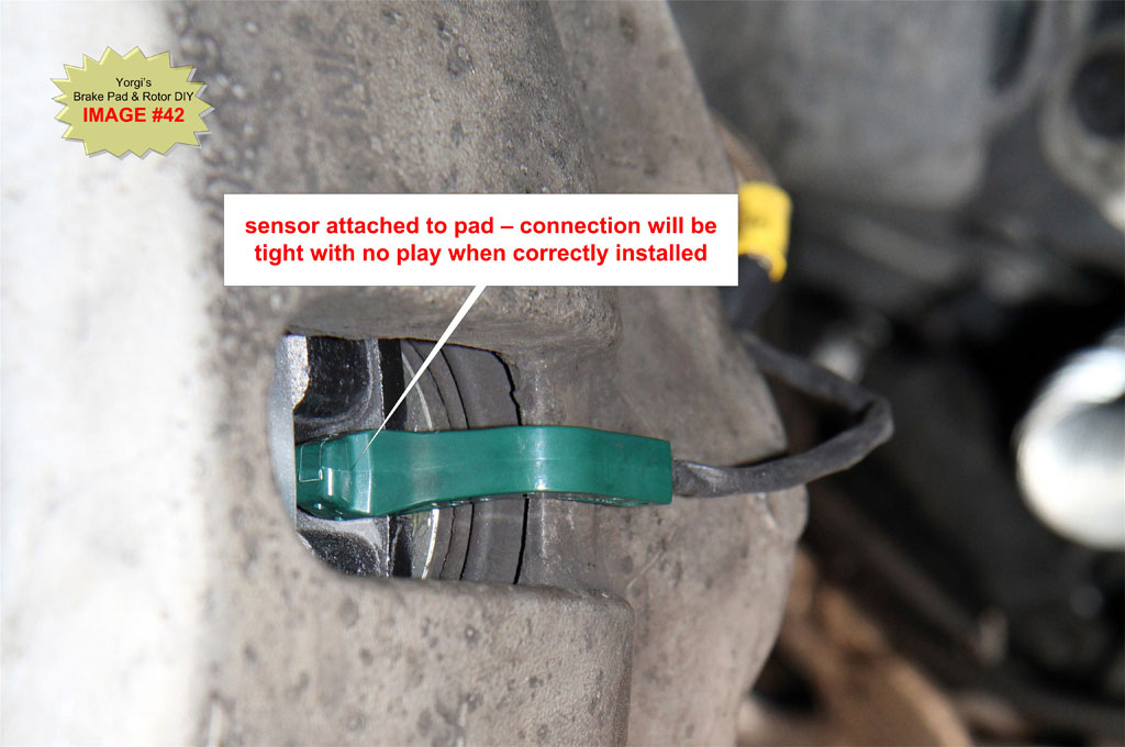
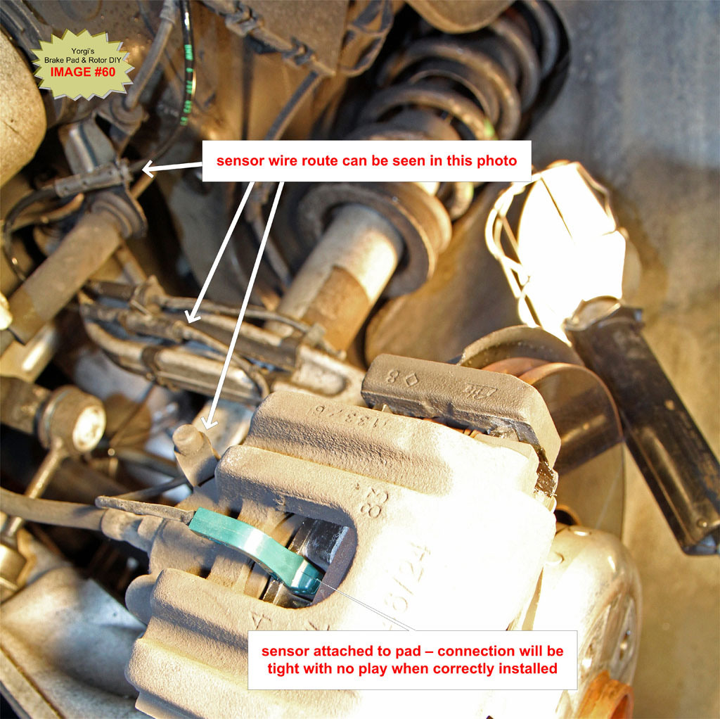
G15. Install brake pad wear sensor
The new sensor should have been plugged into the enclosure in Step G5. Take the green sensor end and plug it into the notch on the top of the inner brake pad. It may take some wiggling and force to get it to snap in fully.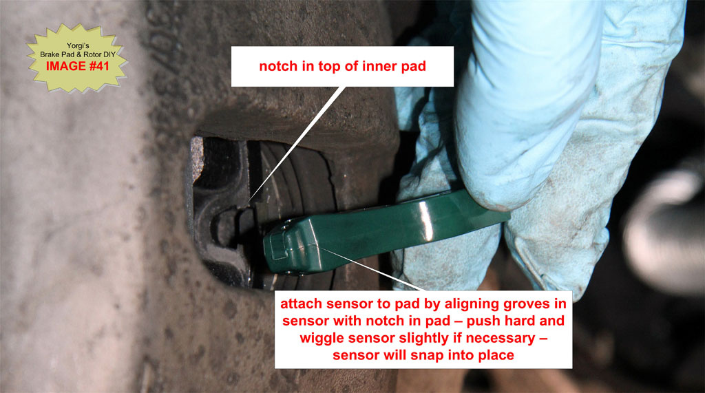
G16. Install spring retaining clip
Position the two outer ends of the clip first then push firmly towards the back of the car on the middle of the clip to engage the lug. You can use the prybar to help push back the clip before inserting the lug. Once in place you can tap the clip with a rubber mallet to ensure it is fully seated.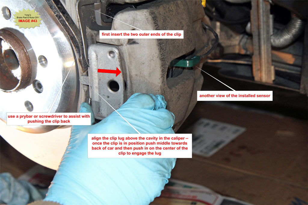
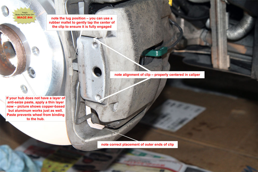
G17. Apply Anti-seize to Hub if necessary
If you do not see silver or copper anti-seize paste on the center hub, apply a thin coating now before installing the wheel. See IMAGE #44.
G18. Install front wheel
Place the wheel on the hub and align the bolt holes. Reinstall the wheel bolts and hand tighten. Drop the car then torque each bolt to 120 Nm (93 lb-ft) in a star pattern. Failing to use a cross/star pattern can warp the wheel.
G19. Right front Brake Pad
Repeat Steps G1 through G18 for the front right wheel. There is no brake pad sensor to replace on the right front wheel.
H. Rear Brake Pad Change Steps:
I will not go into the same level of detail for the rear pads because of the similarities to the fronts. The main differences are the shape of the spring clip and the fact that the outer pads do not have fingers on the back.
If you are changing rear pads only, review the front pad steps above in Section G if more detail is required.
H1. Remove rear passenger side wheel
While the car is still on the ground, use a breaker bar with a 17mm extended socket to loosen the 5 wheel bolts. Break the bolt loose using a star pattern then gently retighten to the point where the bolt can still be removed once the wheel is off the ground.
If you have wheel locks and don't know where the key is, check under the trunk mat where the battery and tools are located which is the standard storage location.
TIP: Cover the socket with black tape to prevent marring the wheels.
Engage the parking brake and chock the front wheel on the opposite side of the car you are jacking to prevent the car from moving while on the jack.
Raise the rear wheel using a hydraulic jack on the right rear jacking point.
Use a "cross wrench" or cordless impact wrench to fully remove the 5 wheel bolts. If the wheel is stuck to the hub after removing the 5 bolts, use a rubber mallet to hit the outer edges of the wheel until it comes loose. You can also sit in front of the wheel and use the heel of a running shoe to kick the outer edges of the tire until the wheel come loose.
TIP: During removal of the last bolt, press the wheel against the hub to prevent it from falling off the hub. You don't want the wheel falling and hitting the brake caliper on the way down.
H2. Remove Spring Clip
Use a large blade screwdriver or small pry bar to remove spring clip from caliper. Pry the middle of the clip horizontally towards the rear of the car until the retaining lug in the middle of the clip is exposed, then pull the clip towards you. 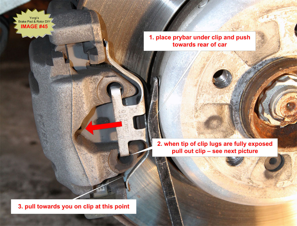
H3. Remove Guide Pins
Pry off the two plastic caps covering the guide pins. See IMAGE #47.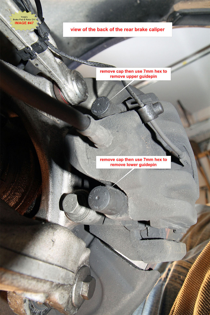
Using a 7mm hex socket, remove the upper and lower guide pins.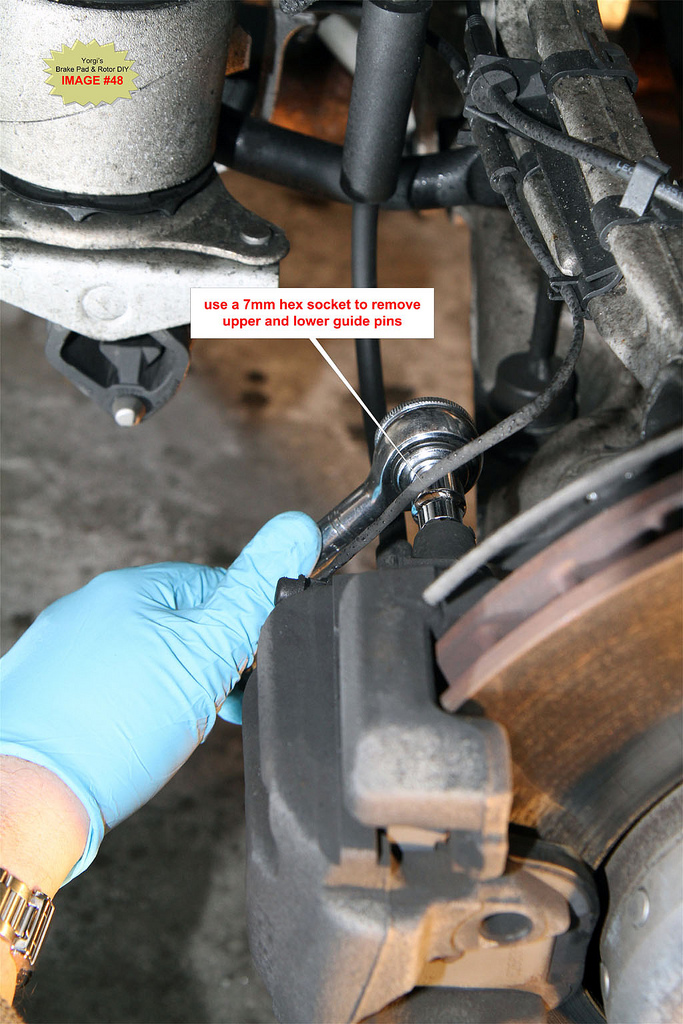
H4. Compress Piston back into Caliper
The piston must be fully pushed back into the caliper to make room necessary for the thicker replacement pads and to clear any wear lip on the rotor edge if it exists.
Place an 8" C-clamp as illustrated in IMAGE #49. Be careful not to pinch wires or the bleed valve at the back of the caliper. Tighten the clamp until the piston is fully seated in the caliper. There should be only mild resistance as you tighten the clamp, if not check the positioning of the C-clamp.
TIP: Keep an eye on the brake fluid reservoir for fluid levels before and after each piston is compressed. If the fluid level rises to near overflow remove some fluid from the reservoir. Brake fluid is an excellent paint stripper and will severely damage paint if spilled. See Section J below for details on how to gain access to the brake fluid reservoir; it's buried under the cabin air filter.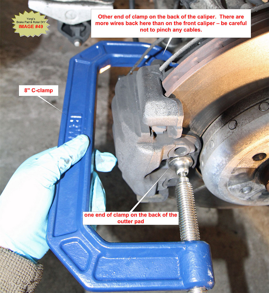
H5. Disconnect Brake Pad Wear Sensor (Front Left and Rear Right wheels only)
BMW TIS Note:
The brake pad wear sensor must be replaced once it has been removed (brake pad wear sensor loses its retention capability in the brake pad)
If you are a die-hard believer in BMW's TIS recommendations, then always order replacement sensors when doing brake pads.
I examine the sensor for wear and if it's in good condition I reuse it. It is still a very good idea to have new sensors on hand in case you break them during removal. They can get brittle over time.
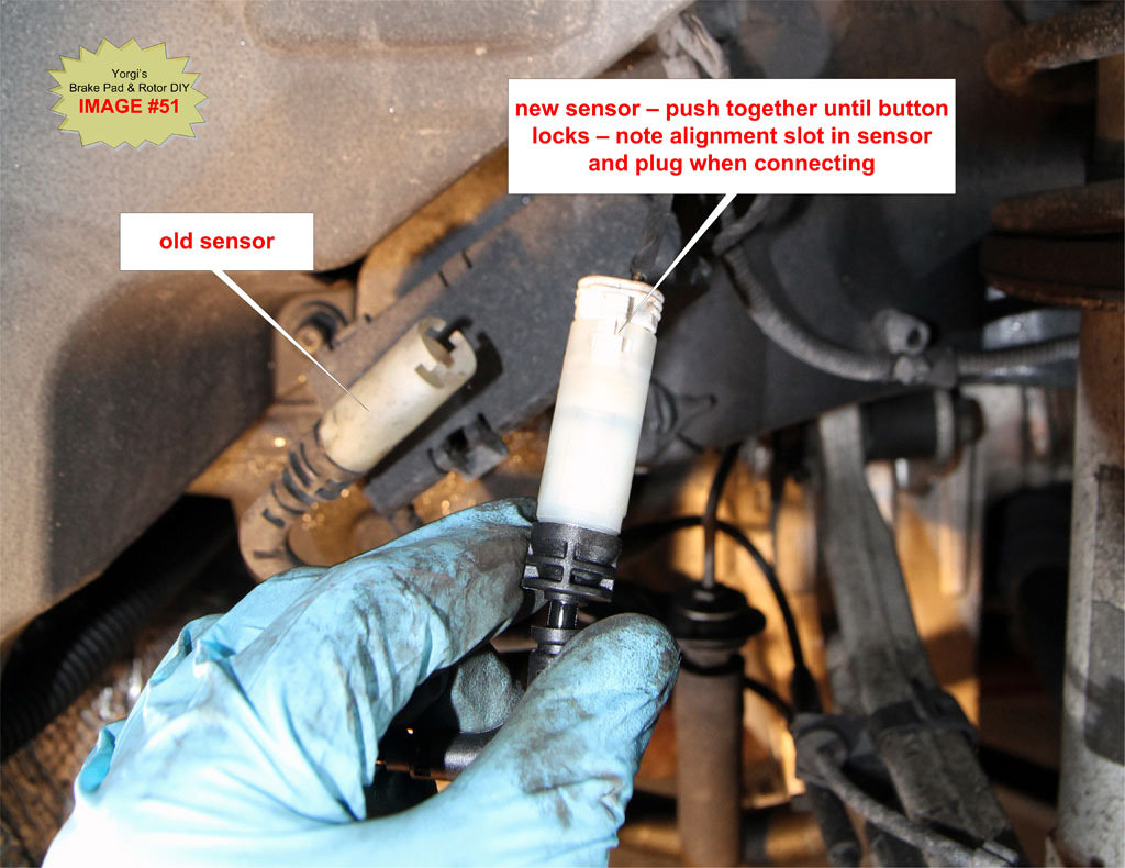
Follow the sensor wire back to the enclosure where it is plugged in. Open cover of housing and unplug old sensor and replace with the new sensor. There is a small push button at the base of the plug that must be pushed to release the plug. Use the old sensor wire to route the new wire back to the caliper. Do not install the "green" end of the sensor into the pad at this point.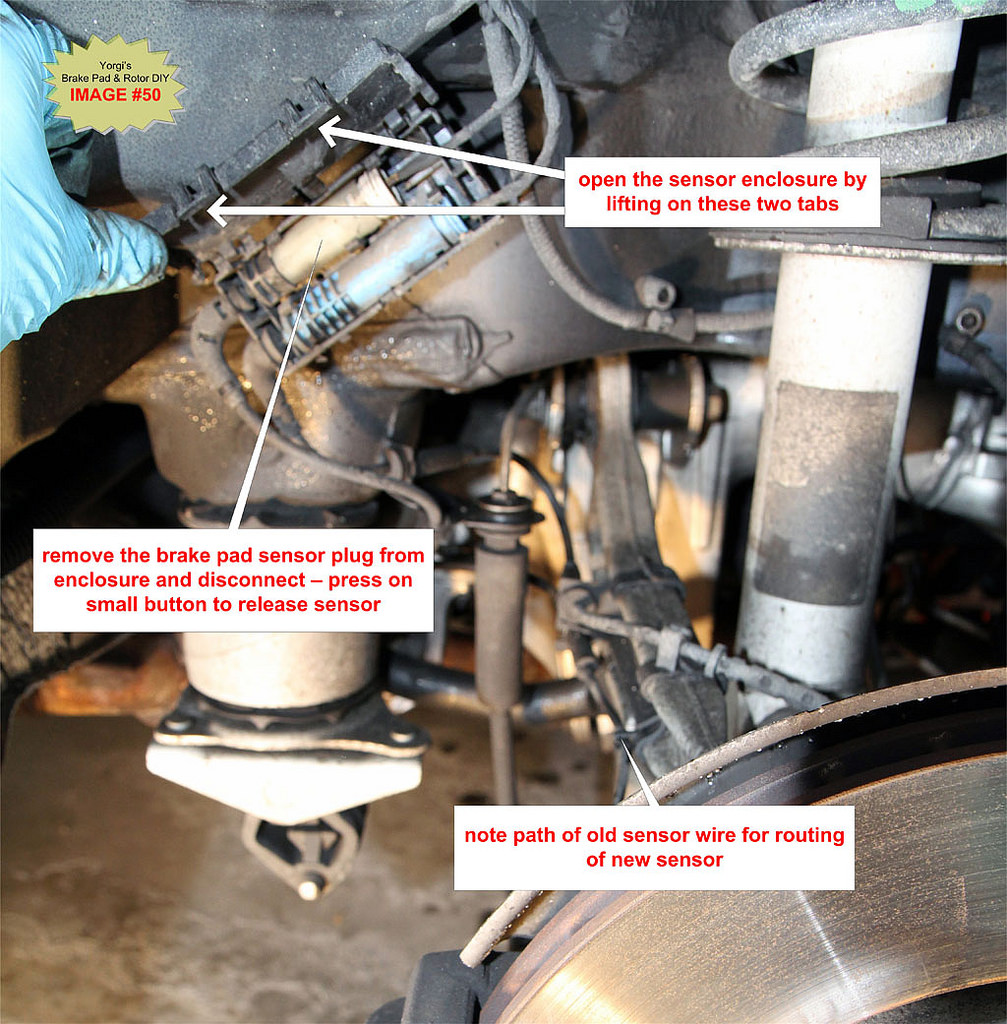
H6. Remove Brake Caliper from the Brake Carrier and hang it from the suspension spring
Wiggle the caliper off the carrier by pulling towards the back of the car. Never let the caliper hang by the brake line - you could damage the lines which may result in bake failure. See IMAGE #19for an example of how to hang the caliper by the suspension spring. You can also place the caliper on an upside down bucket or other suitable stand.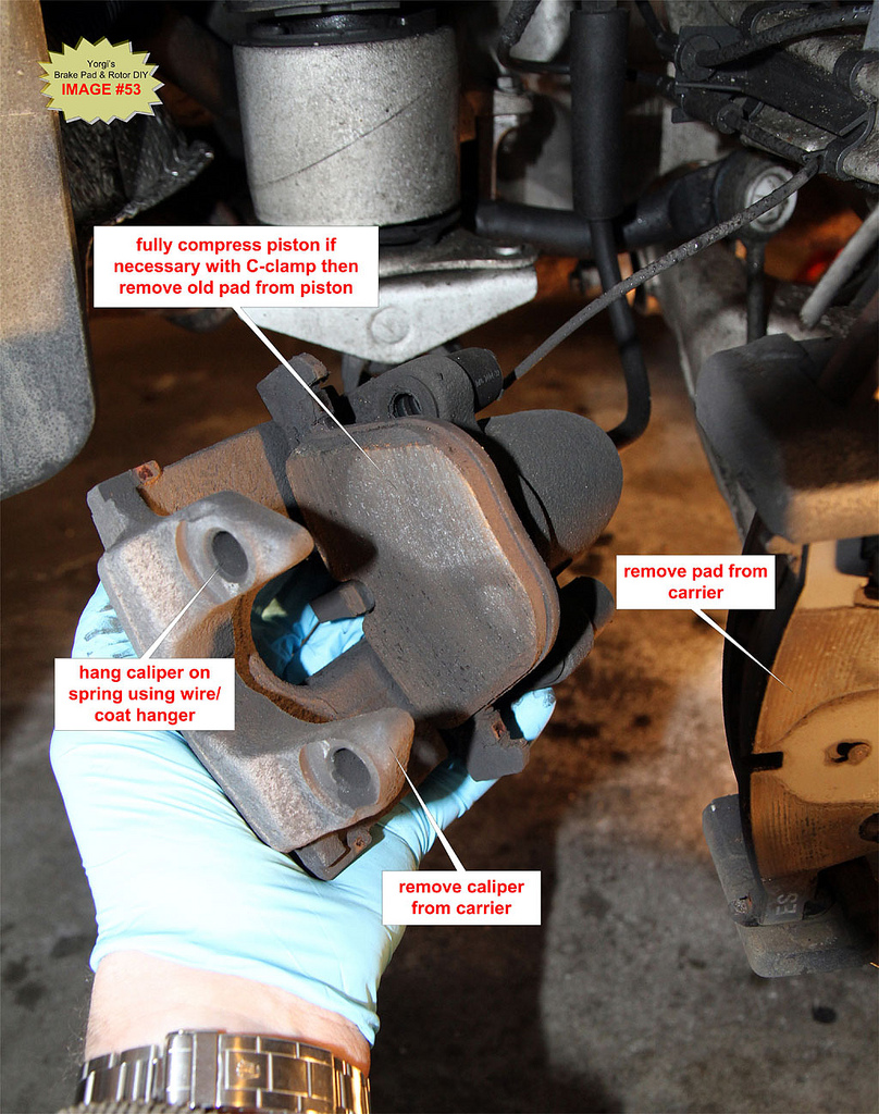
If the caliper does not come off easily the piston is probably not fully retracted. Repeat Step H4 to ensure the piston is compressed.
H7. Fully compress piston back into caliper if necessary
Once the caliper has been removed look at the piston and confirm it is fully compressed. If not use the C-clamp to push on the inner brake pad until the piston is fully retracted. To prevent damaging the piston, NEVER push directly on the face of the piston, always use an old pad or even a block of wood between the clamp and piston face. See IMAGE #20.
H8. Clean brake carrier, caliper and guide pins. Inspect condition of piston rubber boot.
Remove both brake pads from the caliper.
Examine the condition of the rubber boot and piston face. If any rips are visible in the rubber or if the piston face contains heavy gouges or a large amount of rust order a caliper rebuild kit from BMW. It is important to thoroughly clean the surface of the piston and the inside of the caliper directly across from the piston. These two areas contact the backs of the pads and if they are not clean and smooth brake squeal can occur.
Guide pins should always be removed and thoroughly cleaned to ensure smooth operation of the caliper. The caliper slides on these pins and will bind if they are overly dirty resulting in rapid pad wear.
DO NOT grease the guide pins. Unlike other cars which have metal-on-metal pins BMW uses a rubber-on-metal design that will bind the calipers if grease is used on the pins.
BMW TIS Note:
Replace guide screws which are not in perfect condition.
If you cannot get the pins clean or if you notice groves in the pins once they are cleaned replace the pins, they are not expensive.
Cleaning guide pins and the caliper-to-pad contact areas is dirty work but failure to do this will contribute to the likelihood of brake squeal and rapid pad wear. Binding calipers is a major cause of squealing.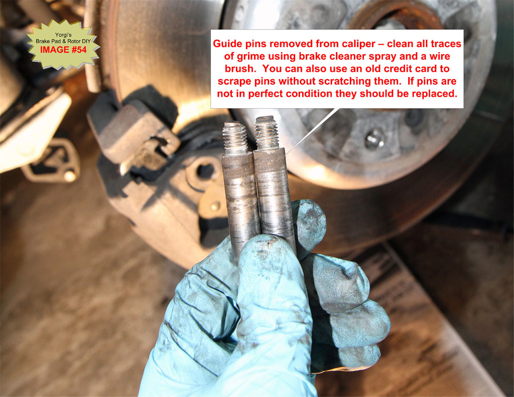
TIP: Use brake cleaner, wire brushes and an old credit card to scrape off deposits on guide pins.
I use small brass brushes to clean the caliper-to-pad contact points thoroughly. A small blade screwdriver can be used with light pressure to scrape off large deposits. Spray brake cleaner fluid liberally as you go. See IMAGE #21 and IMAGE #23 for a before/dirty and after/clean caliper and pins.
TIP: Place newspaper under the caliper to catch brake pad dust/grime that falls during cleaning. It is also a good idea to wear a face mask and eye protection while cleaning the calipers since quite a bit of dust can be kicked up if the calipers are very dirty.
H9. Check Brake Rotor thickness and runout
The minimum allowable rotor thickness is stamped on the rotor hat. See IMAGE #24
Use a brake rotor vernier caliper (available on eBay for $30) to measure rotor thickness. A brake rotor vernier caliper will reach over any outer lip caused by worn rotors. You can also use a micrometer with a 1"-2" range to measure rotor thickness. As a workaround you can use a standard vernier caliper with two spacers placed on each face of the rotor then subtract the thickness of the spacers to get your reading.
If the rotor is below the stamped minimum then the rotors must be replaced. See Step H10.
OPTIONAL: measure rotor runout
See Step G9 for measuring runout.
H10. OPTIONAL – Replace Brake Rotors If Necessary
Replace brake rotors if thickness is found to be below the minimum thickness stamped on the rotor hat. Always replace rotors in pairs. Note that rear rotors contain brake shoes used for the parking brake. They can be a little more difficult to remove due to the shoes. Disengage the parking brake if removing the rear rotors.
See Step G10 for rotor replacement details.
H11. Prep Brake pads for installation
OPTIONAL: See Step G11 for brake pad prep details.
H12. Apply Anti-Squeal Compound to Caliper and Carrier
Apply a thin coat of anti-squeal compound to the piston surface being careful not to get any on the rubber seal which can cause swelling.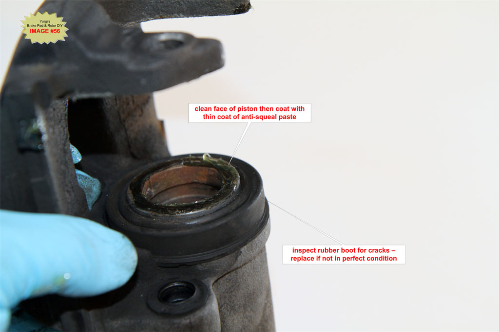
Apply a thin coat of anti-squeal compound to where the back of the outside pad comes in contact with the caliper (directly across from the piston face) and to the caliper where the outer pads ears will make contact. 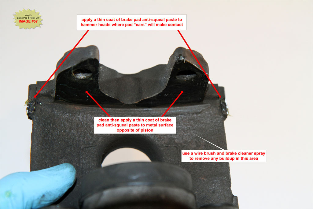
Apply a thin coat of anti-squeal compound to the caliper carrier at the pad contact points. See IMAGE #58.
H13. Install brake pads and caliper
Push the inner pad, the one with 3 fingers on the back of the pad, into the piston. Place the outer pad onto the other side of the caliper. Note there are no fingers on the outer pad, unlike the front outer pads.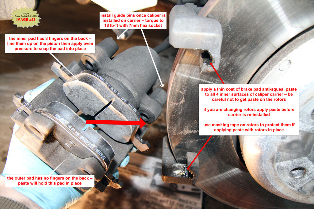
With the new pads installed, push the caliper back onto the caliper carrier.
H14. Install Guide Pins and caps
Torque to 30Nm (22 lb-ft). Do not over tighten the guide pins and ensure they are clean before installing. Install the 2 plastic cover caps.
H15. Install brake pad wear sensor
The new sensor should have been plugged into the enclosure in Step H5. Take the green sensor end and plug it into the notch on the top of the inner brake pad. It may take some wiggling and force to get it to snap in fully.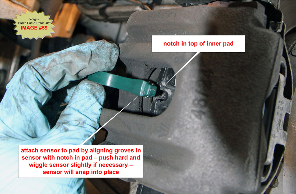
H16. Install spring retaining clip
Position the two outer ends of the clip first then push firmly towards the back of the car on the middle of the clip to engage the two hooked lugs. You can use the prybar to help push back the clip before inserting the hooks. Once in place you can tap the clip with a rubber mallet to ensure it is fully seated.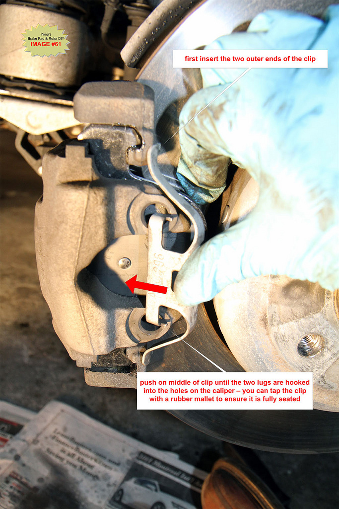
H17. Apply Anti-seize to Hub if necessary
If you do not see silver or copper anti-seize paste on the center hub, apply a thin coating now before installing the wheel. See IMAGE #44.
H18. Install rear wheel
Place the wheel on the hub and align the bolt holes. Reinstall the wheel bolts and hand tighten. Drop the car then torque each bolt to 120 Nm (93 lb-ft) in a star pattern. Failing to use a cross/star pattern can warp the wheel.
H19. Left rear Brake Pad
Repeat Steps H1 through H18 for the rear left wheel. There is no brake pad sensor to replace on the left rear wheel.
I. Pump brakes until the pedal gets hard before attempting to drive the car.
Retracting the pistons results in a soft pedal. Press the pedal several times with the car started until it becomes firm.
J. Check brake fluid level
For some reason BMW decided to bury the brake fluid reservoir under the left cabin micro filter. After the elimination of the oil dip stick, I think this is one of the most senseless design decisions found on late model BMWs.
J1. Remove the driver’s side cabin microfilter and cover.
Flip the long bar clip on the left side of the cover. Pull top of bar towards the front of the car.
Using a 13mm socket turn the plastic lock screw on the right side of the cover 45° counterclockwise then lift out the cover. The filter should come out with the cover.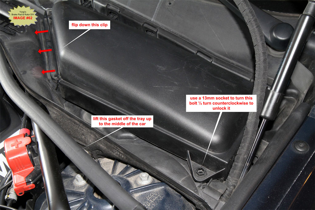
TIP: Use a deep 13mm socket and turn by hand without attaching a ratchet. The plastic screws do not require much torque to turn.
J2. Pull the large rubber gasket in front of the air filter.
Simply lift it up and set it to the side all the way up to the middle point of the car. See IMAGE #62.
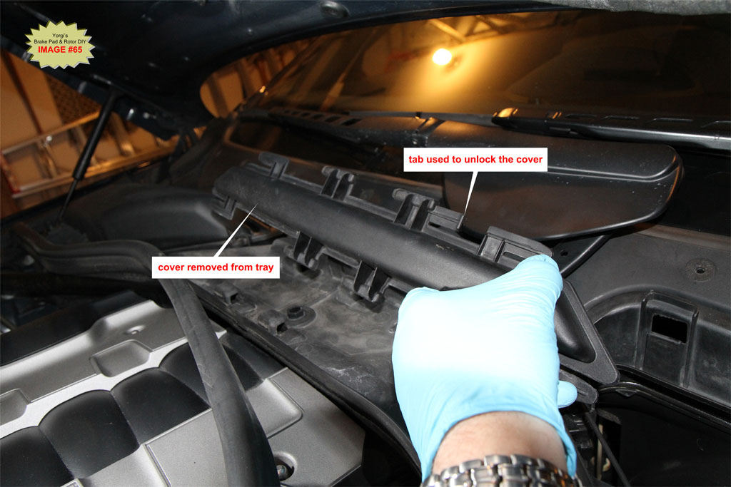
J3. Remove the center tray cover/clip
In the center of the engine bay by the windshield, there is a long plastic cover/clip that locks the two microfilter base plates together. Lift up on the locking lever and slide this large cover/clip to the right and remove it.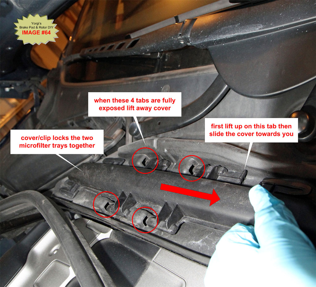
J4. Remove base plate Torx screw
Use a T25 Torx key to remove the base plate screw.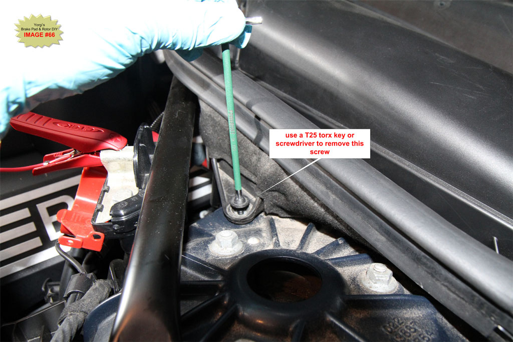
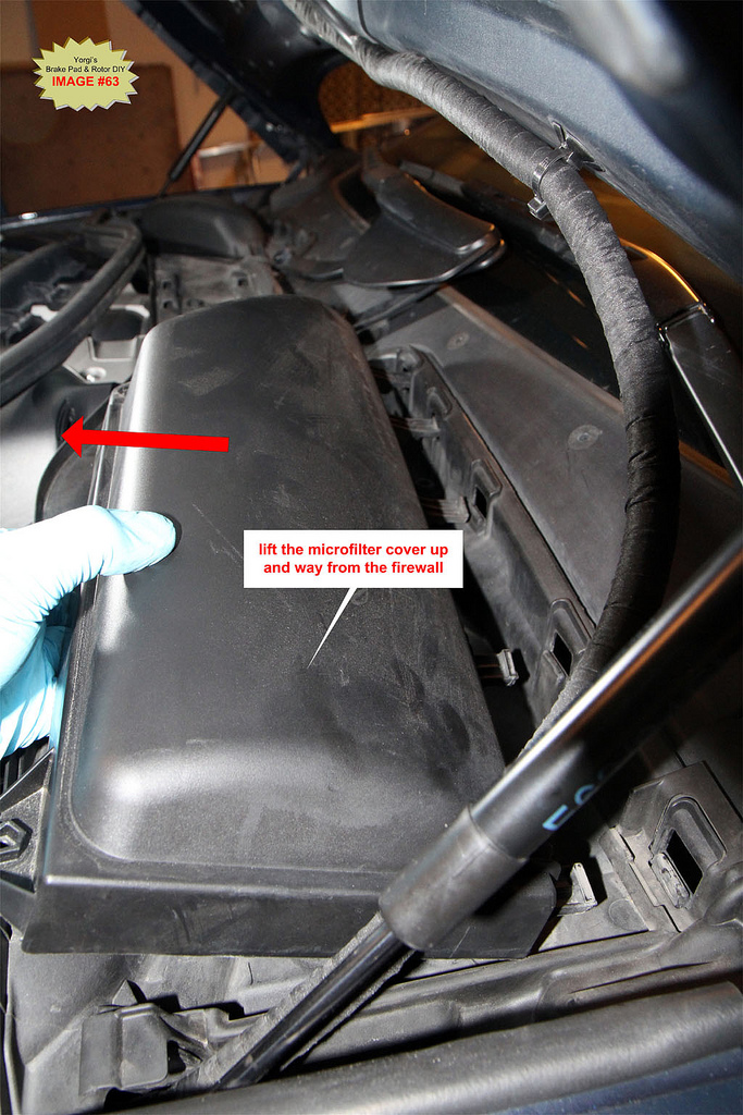
J5. Remove the microfilter base plate
Pull out the soft rubber cover to the far right of the base plate. It covers a gap between the base plate and the fender up by the windshield.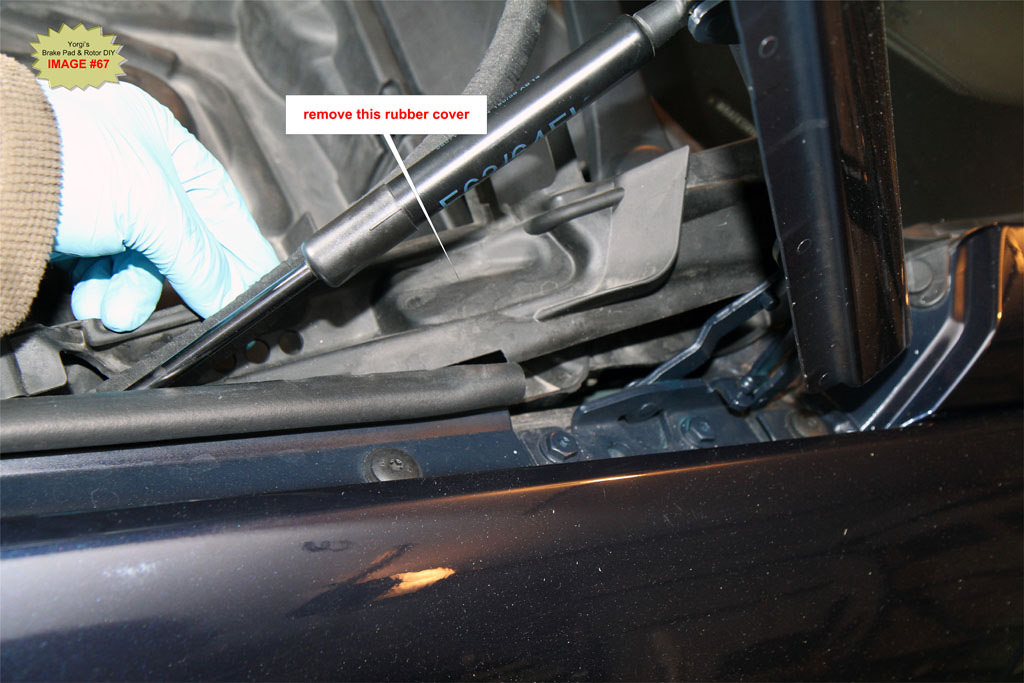
Turn the 4 plastic lock screws 45° counterclockwise then lift out the base plate to expose the white plastic brake fluid reservoir. 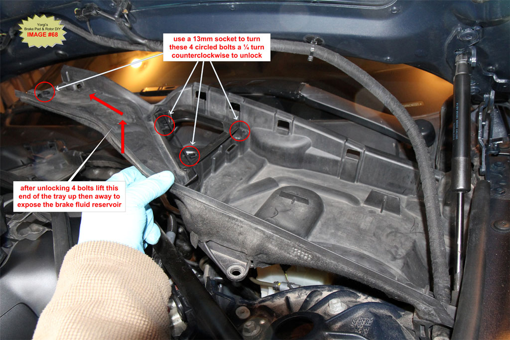
J6. Check the fluid level
Ensure the brake fluid is at the MAX line. If not add fluid as necessary. CAREFUL! Brake fluid is a very good paint stripper. Do not spill even a drop of fluid on the cars paint. Use rags/towels to prevent spillage of brake fluid.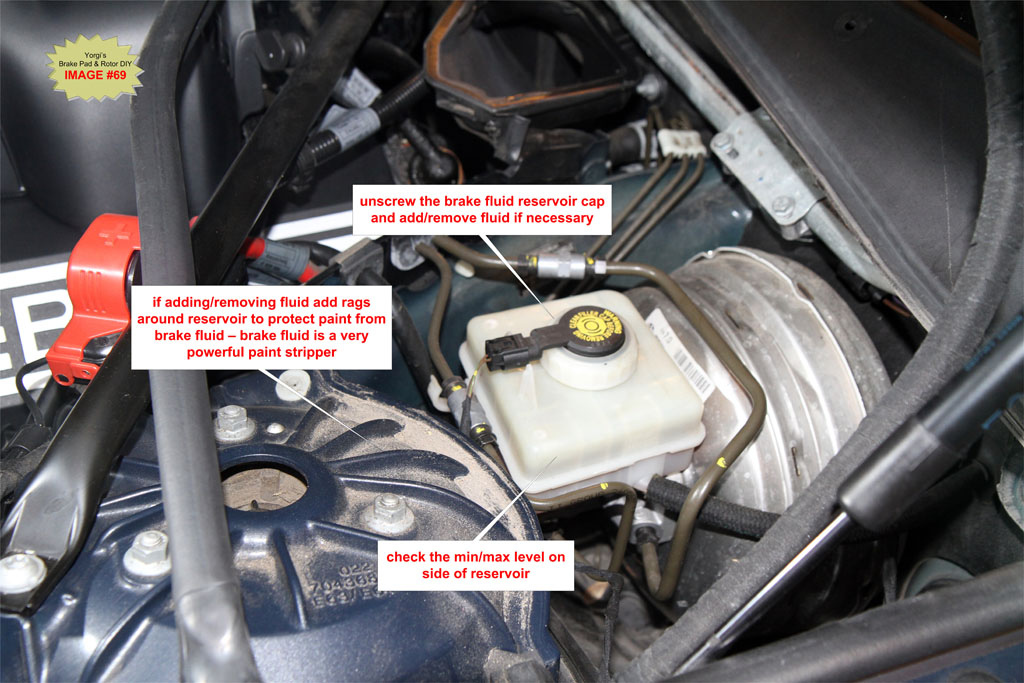
J7. Replace the driver’s side cabin microfilter and cover.
Installation is the reversal of removal. Follow steps J5 back through to J1 to install the microfilter and cover.
K. Steps to Reset Brake Pad Check Control:
You can reset the Check Control brake service light with diagnostic software (e.g. CarSoft) or manually using the following steps.
Notes:
•Perform the following steps quickly. A few seconds of inactivity between button pressing and the car will exit the Check Control reset mode. It may take some practice before you get the hang of it.
•There are two buttons involved and two types of pressing. “Press” means press and release the button. “Hold” means press and hold the button down until the display changes to the desired mode.
•Pictures below show mileage in kilometers, US cars will be in miles.
K1. Insert the remote key fob into the ignition lock
K2. Press the {Start/Stop Engine} button to put the car into “ignition on” mode. Look for all the warning lights to come on in the instrument cluster; it may take more than one press. (for manual transmissions make sure you are not depressing the clutch, for auto transmissions keep your foot off the brake)
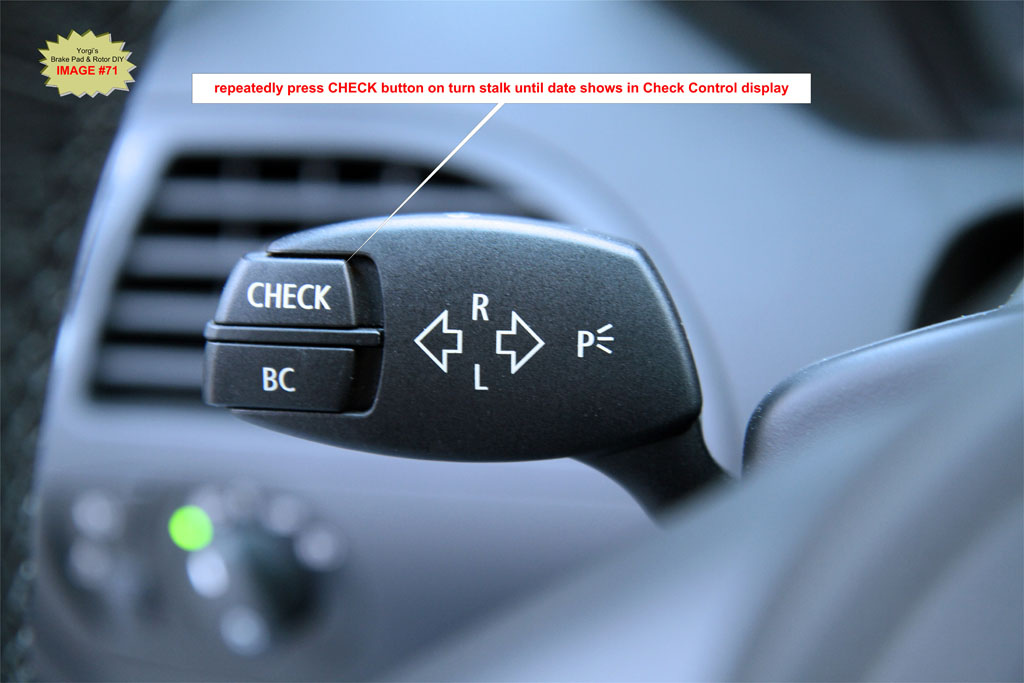
K3. On the turn signal stalk, press the “CHECK” button repeatedly until you see the date displayed in the upper middle Check Control screen located between the speedometer and tachometer.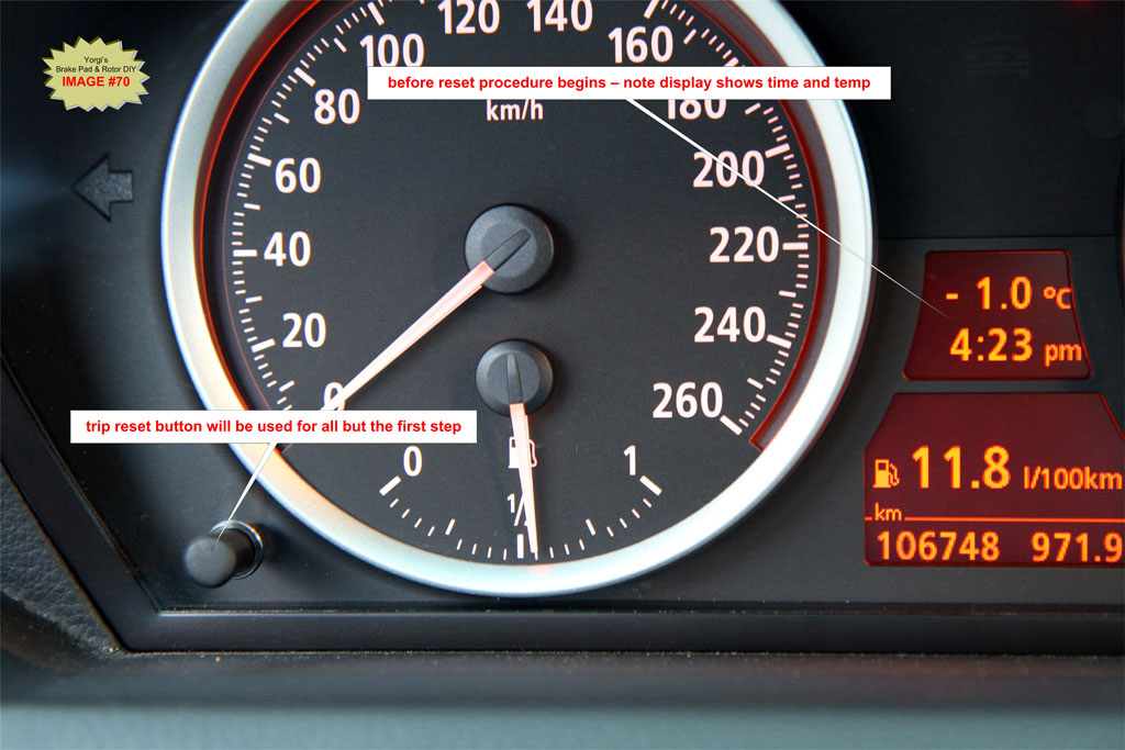
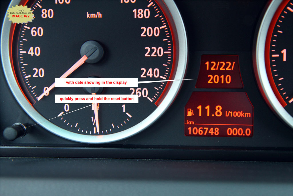
If you end up waiting too long and fall out of Check Control reset mode, start over at Step K3.
K4. Within 5 seconds of switching to the date in Step 3, hold the trip odometer “reset” button for approximately 5 seconds. An exclamation mark inside a triangle symbol will display followed by one of the 7 Check Control symbols (Check Control symbol varies).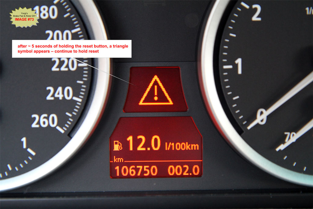
You have now entered the Check Control reset mode. 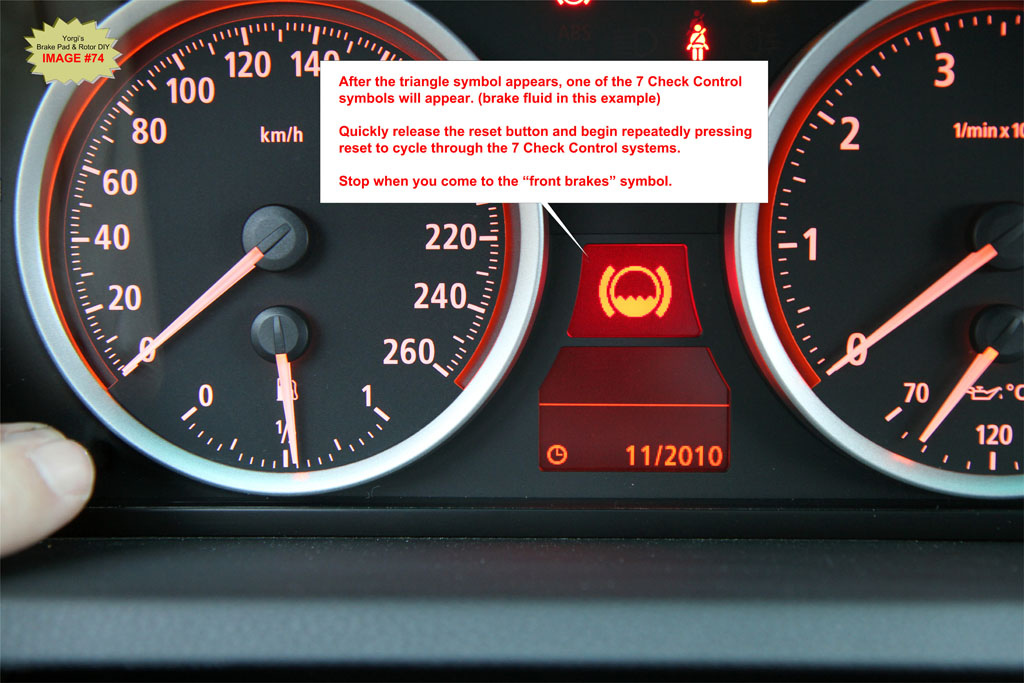
TIP: If you see very small German text in the upper Check Control screen you held the reset button too long in Step 4 after the triangle symbol was displayed. Remove the key fob and start over at Step 1. Release the reset button immediately after seeing the first Check Control symbol that follows the triangle symbol.
K5. As soon as you see one of the 7 Check Control symbols, release the “reset” button and re-press it quickly multiple times to step through the various systems that can be reset. If the CheckControl symbol has a bright red background then service is past due. Systems available for resetting are as follows: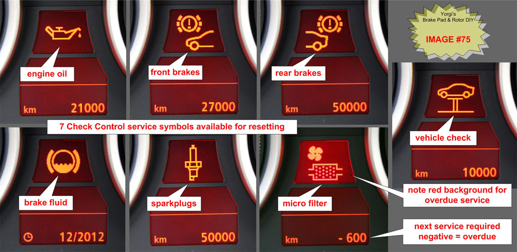
In this case you want to stop cycling when you see a “front brakes” symbol.
K6. Once you have landed on the “front brakes” symbol, release the “reset” button and hold it for ~5 seconds until the text “RESET?” appears just below the “front brakes” symbol.
NOTE: IMAGE #76 shows the “Oil Can” symbol but you should be resetting the Front Brakes symbol.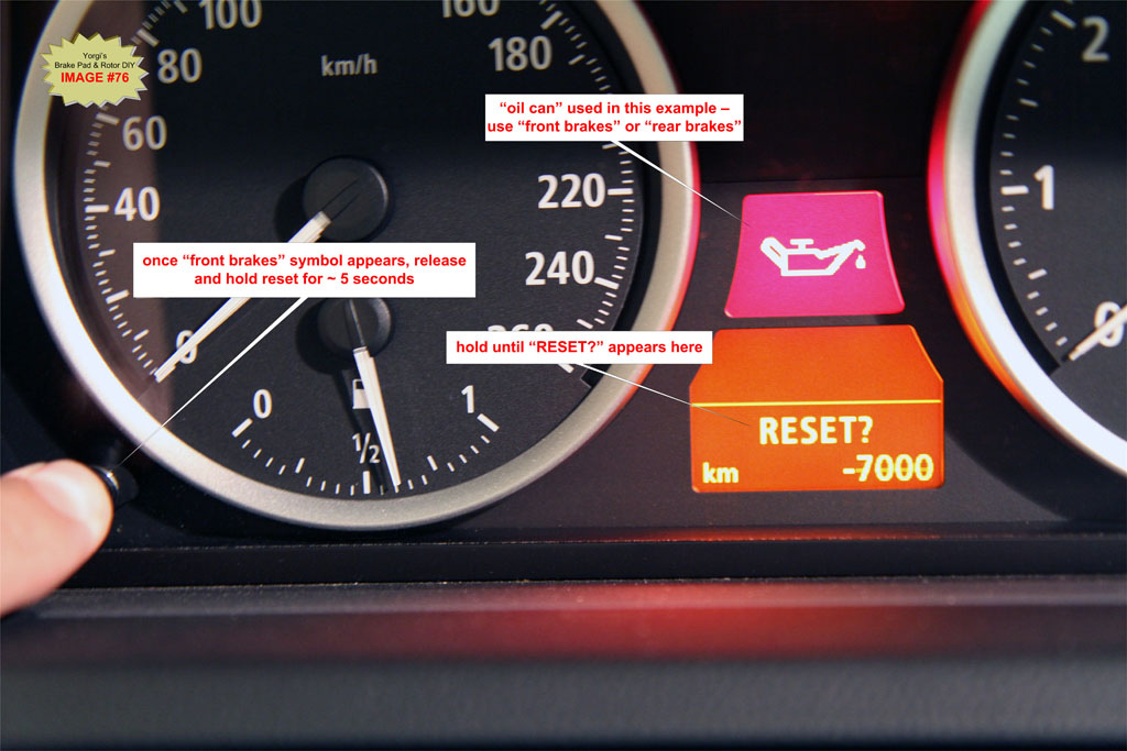
K7. Release the “reset” button and hold it for another ~5 seconds. The red background will disappear and the “remaining distance (or date) until next service” will reset.
NOTE: IMAGE #77 shows the “Oil Can” symbol for reference only.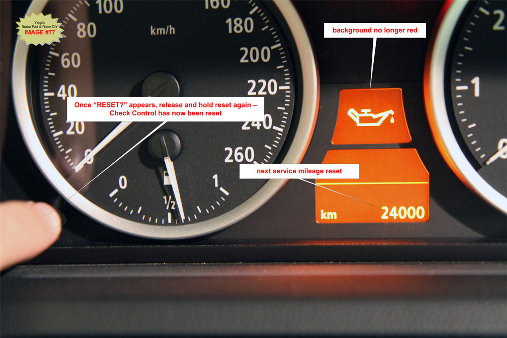
K8. Repeat Step 3 to Step K7 but stop on the “rear brakes” symbol. See IMAGE #75.
L. Bed in Brake Pads
This is a very important step. Bedding transfers a layer of pad material onto the rotor which is necessary for proper brake performance. It is critical to do this when rotors have been replaced or when you are changing to a new pad material.
If your pads did not come with specific bedding instructions, then follow the excellent instructions provided by Zeckhausen Racing here: Zeckhausen Racing Brake Bedding Instructions
Congratulations you are FINISHED. Clean up and go grab a beer.
Finally created an Adobe PDF version which should make printing the instructions a lot easier. Had to break it into 2 parts due to 7MB attachment limitations.
BMW 650i Brake Pad Change DIY by Yorgi Part1.pdf
BMW 650i Brake Pad Change DIY by Yorgi Part2.pdf