You must be logged in to rate content!
9 minute read

Caster/Camber and Toe gauge tool (homemade)
Compliments of JRouche @ pro-touring.com
5-18-2010
I have my front end all built now and need to align it. It has such a variety of parts that taking it to an alignment shop is outta the question. So I looked into some of the caster/camber gauges available. There are alot out there. They are simple and not too expensive. But most of them work with wheels that have a lip to capture the arms. My wheels dont have a lip. So I was gonna have to make one for my wheels. I though about making one that would set on the spokes of the wheels. That was gonna be my first choice. Then I saw a hub mounted one from Longacre.
That looked like the sweet setup. Theirs is a magnet mounted one. No good for me, I have all aluminum. But I saw that my Wilwood brake hubs have a threaded cap and hub. Perfect!!! So the measuring and building began...
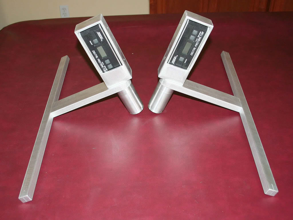
Oh, and their setup is just a toe gauge, but you can buy an adapter to use it with their digital camber/caster gauge. I had a couple of new SPI digital protractors hanging around waiting for a use. So here is the use. Long thread and many large pictures.
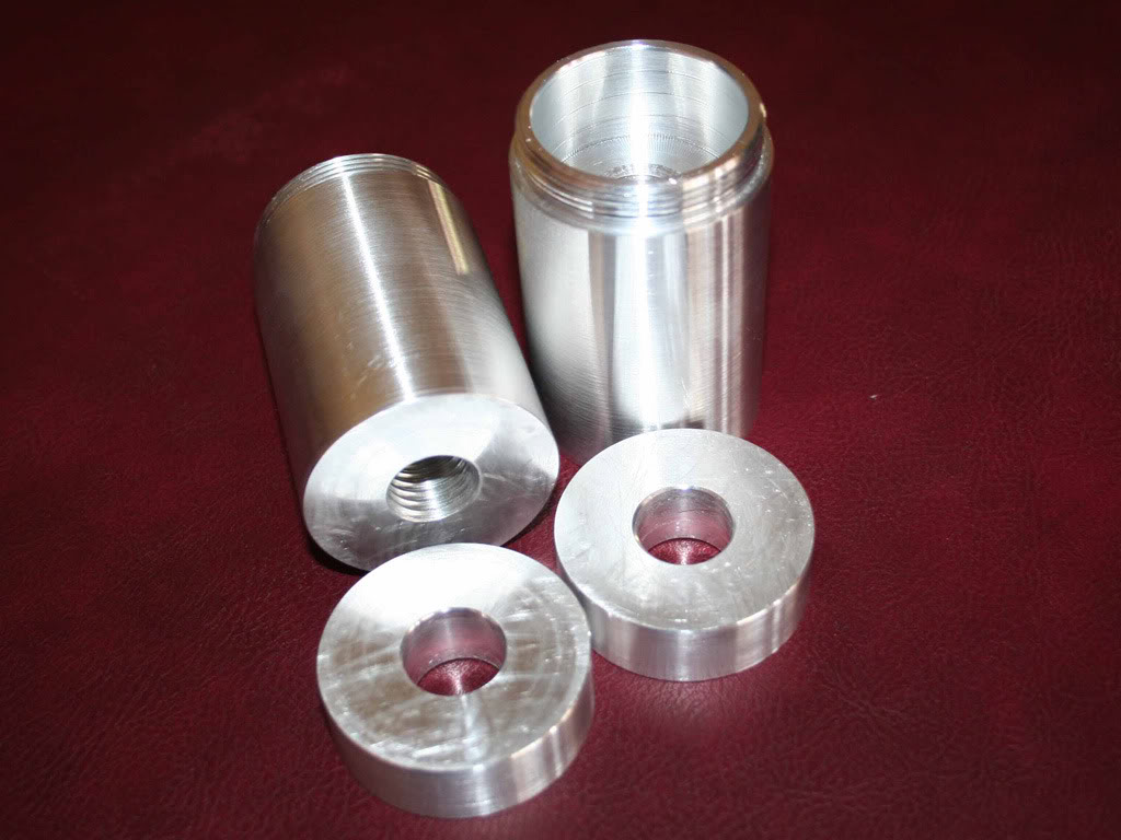
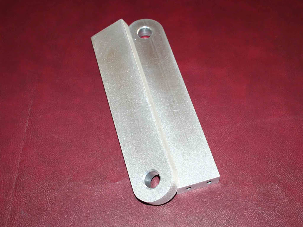
So it started out with me measuring the thread of the brake hub cap. Once that was set I needed to make an adapter for the hub. All the stock used was on hand so I didnt make it as custom as it could be, just using material that was on the shelf in my house garage. And its just a tool, not jewelry
I needed alot of clearance on the inside of the thread to clear the castle nut and spindle. So alot of aluminum got hogged out.
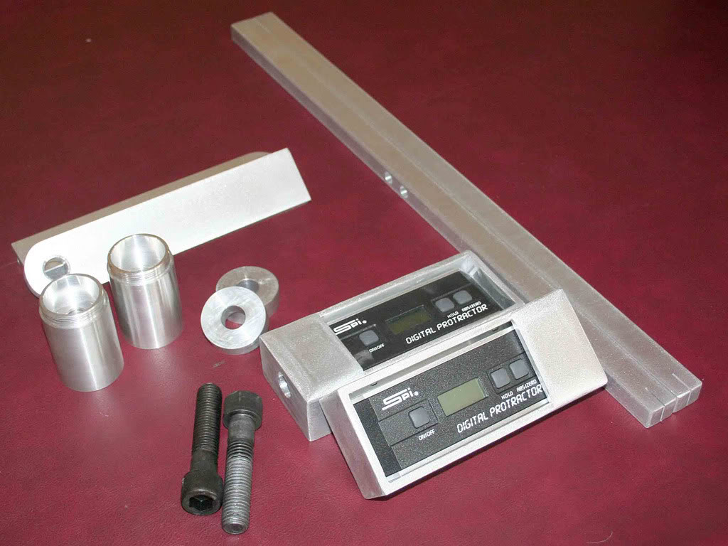
Why the spacers? Back to material on hand. I happened to have a 2" bar that when split in half was just too short to clear the sidewall of the tires. So spacers were needed.
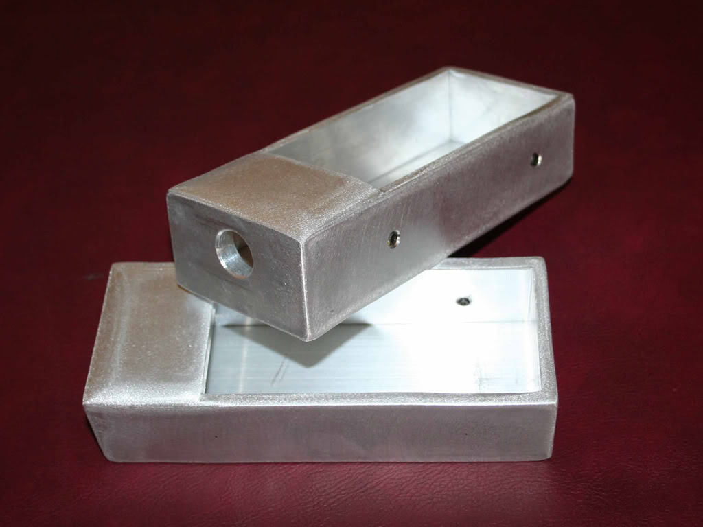
Next was a housing for the digital protractors. There are alot of ways to do it. I do have a cnc milling machine. But to be honest, Im still learning to draw parts up in the cad program and Im not all that proficient. So welding up a box was an option. And again, welding aluminum is new to me. So I needed the practice. Glad I did. I need to get used to welding aluminum. Steel is so different and Im comfortable TIG welding steel, time to branch out.
So I cut some plates of aluminum and clamped them up for welding. The beads weren't too bad. I HATE grinding welds down, it shows that the weld wasn't very nice. Well you get the idea, I ground down my welds LOL
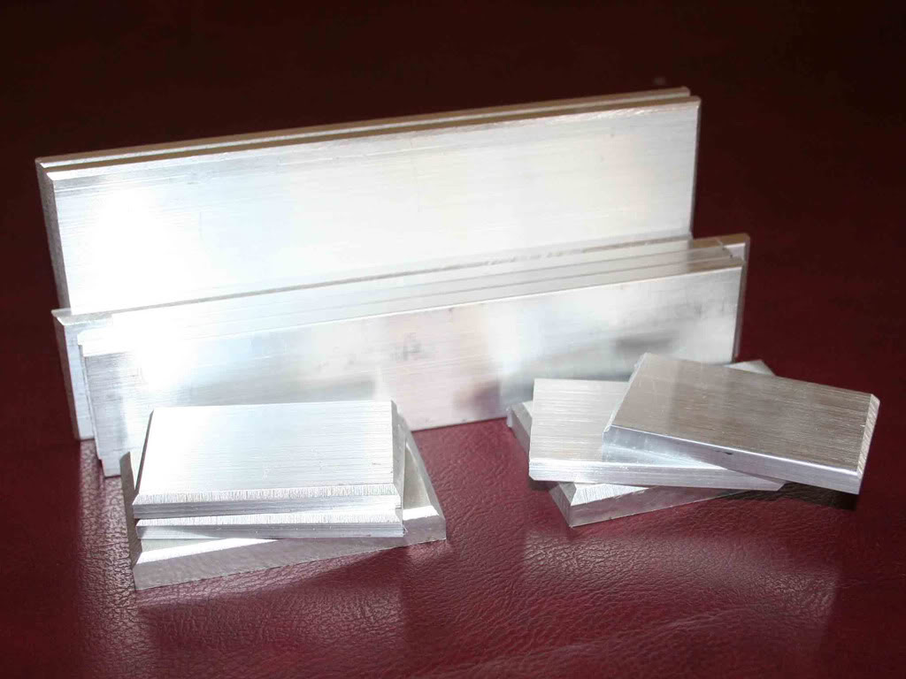
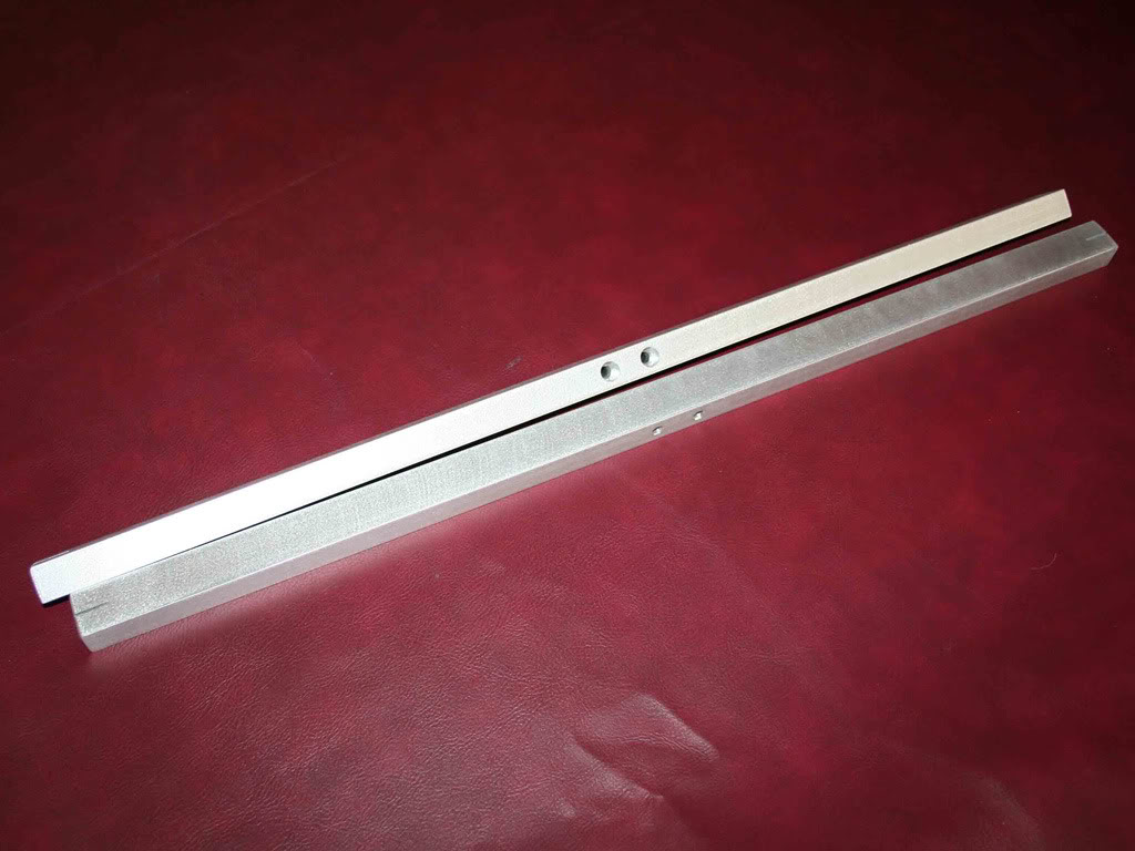
Next was the vertical bars for the toe gauge. Simple cutting, drilling and sanding.
The lower cross bars for the toe gauge. My car has 26" diameter tires so the lower bars are 26" long for proper toe setup.
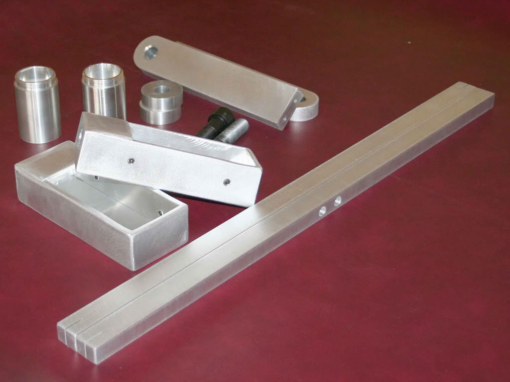
All the bits and pieces done.
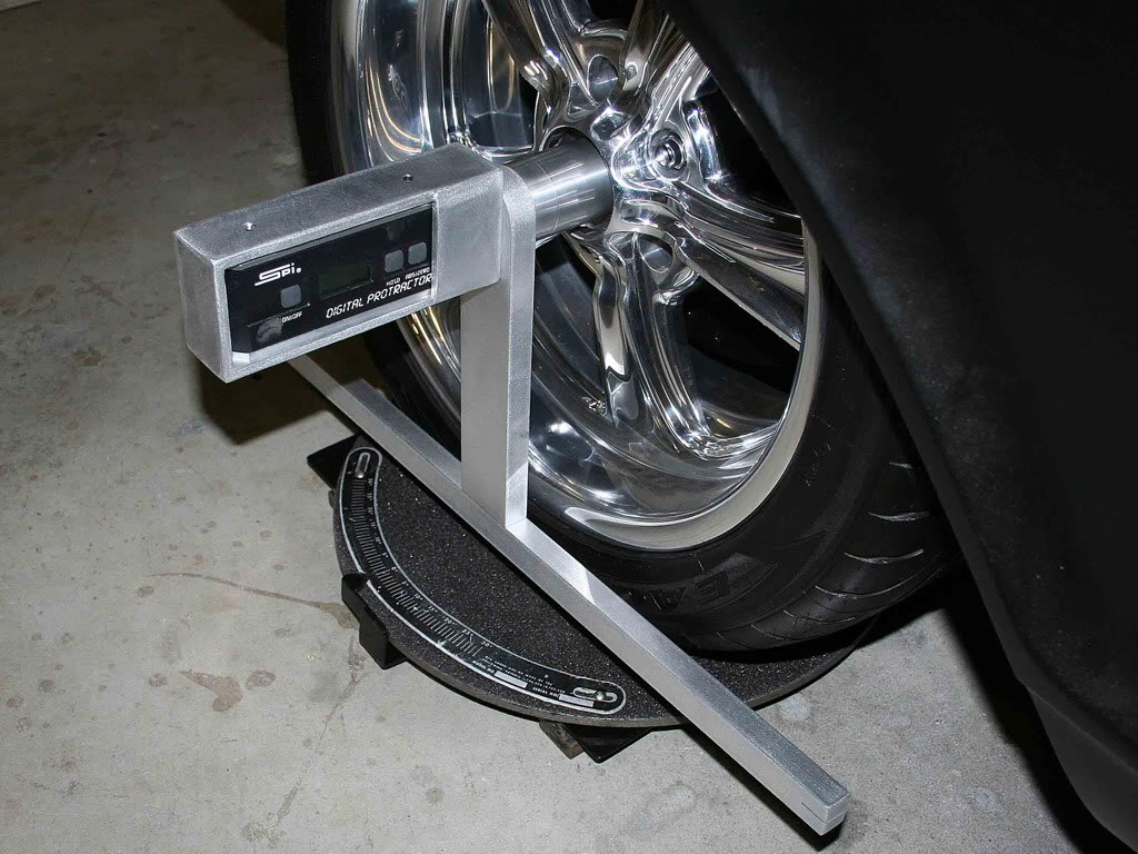
This is how the protractors or digital levels set in the boxes. They are captured by small set screws that align with the Vee on the body of them. Keeps them from flopping out. The reference plane that is tight to the vertical plane is the bottom of the box. When I welded the box up I made sure the upper and lower plates of the box were perfectly square with the end plate that mates to the round spacer.
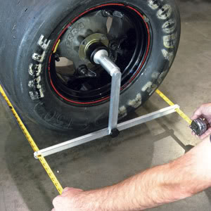
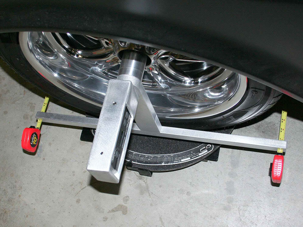
Then when assembled off the car this is what the whole thing looks like.
To mount it to the car the spud goes on first.
Then the 3/4" bolt is put into the box before the protractor and thread the entire assembly to the car.
Why a large 3/4" bolt? Nuther screw up. When I was boring the threaded side of the spud I ran the drill bit all the way through. Knowing I would need a hole for the connector bolt. But dummy me, I went a couple sizes too large for what I needed. I was hogging out the OD threaded side and didnt want to have to bore alot. So I used a large drill bit to remove a major portion of material. I should have stopped at the major depth on the OD thread side and kept the other sides hole smaller to tap it for a 1/2" bolt. No loss for me. But just shows planning actually works. I didnt draw it up or plan it. I just went to town cutting metal.. Just showing, it is ALWAYS a good idea to put yer build on paper.
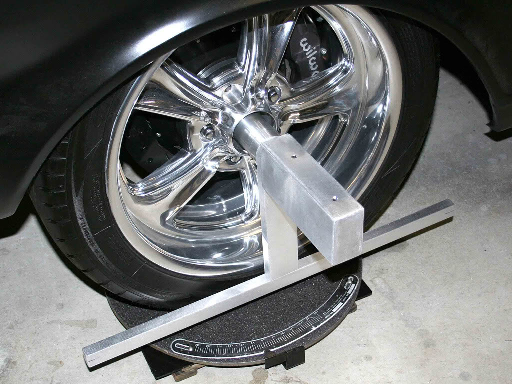
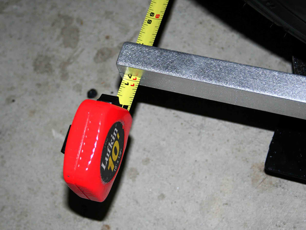
Ok... Now the sweet part of this rig. The toe measuring. Thats why I made two of these fixtures. Hook a tape on the right side of the car and measure the left side. Its really nice. The lines are sharp enough that you can get a toe reading to within a 1/32" if you need to. And the lower arms dont flex during measuring. Its pretty stout.
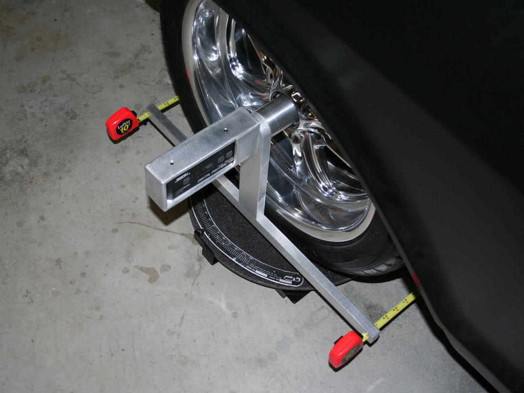
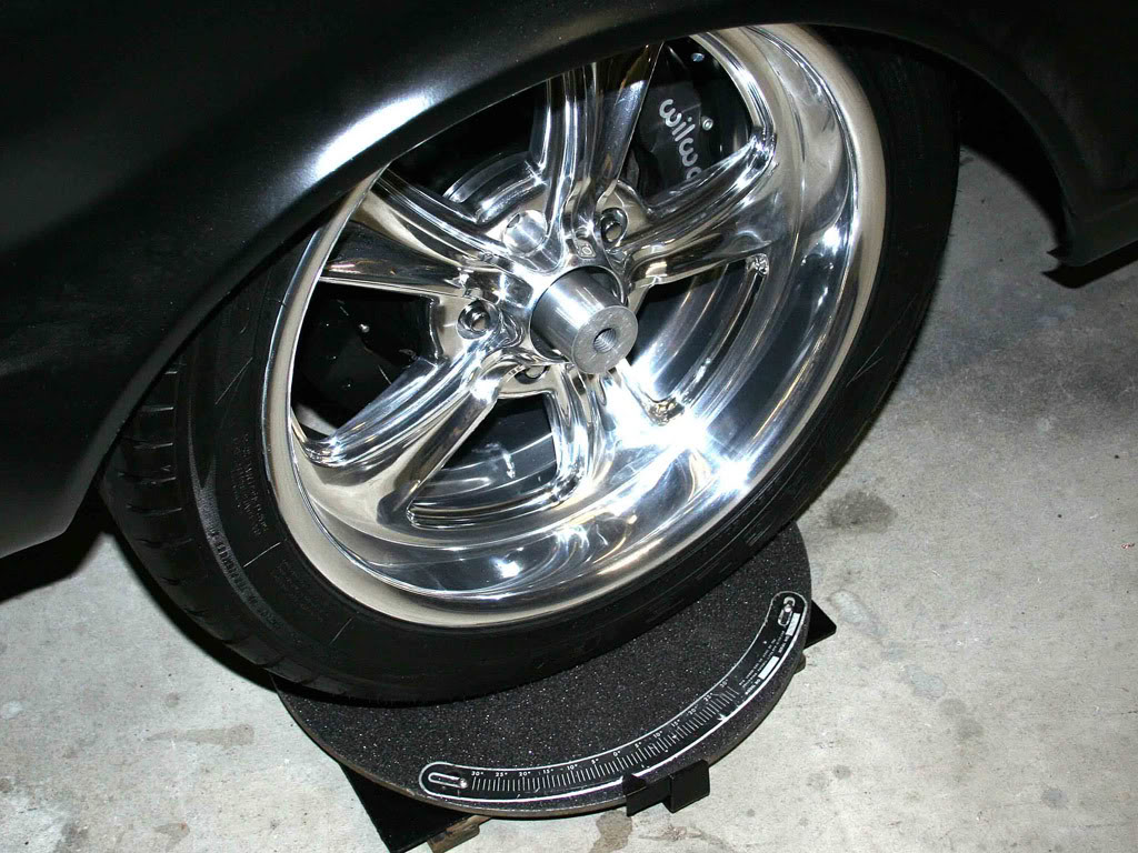
So Im gonna go ahead and do an alignment. You see the turn plates under there. They are a must IMO. Those are full floaters. Meaning they will slide fore and aft and in and out (sideways) along with rotation all on a BIG bearing. Some Bear plates I picked up on the cheap.
Anyway, this alignment tool can be made by anyone with some simple tools. And even easier if you have a lipped wheel. No need to go with a hub mount. Hope you enjoy the pics as much as I enjoyed making this tool. JR
5-19-2010
And this is why I come here and talk about my car issues. So I can get some info that will help me with what I need to do. And double check my thinking. You are completely correct. Thank you sir!!!!!
I do need to put in the correction factor. I have the instructions for the unit I tried to copy. Longacre unit ..
http://www.longacreracing.com/instru.../78295v4PI.pdf
And I didnt completely read the instructions until now, with your info. They run the tire over 15* then LEVEL the protractor and zero it. Then sweep back 15* for caster. And Ill be completely honest, I over looked that step, leveling of the head when it was at 15*.
Thanks for the heads up and Ill defiantly make sure to take into account for the 1.5 factor when checking caster using it. And instead of leveling the head Ill introduce the 1.5 factor and stick with the 20* numbers. Thanks... JR
5-20-2010
Haha.. Well, took two days for my set so 60 days. Actually, for a run of 30 of them would be alot less. 30 would be done in less than a month. But I would change some things. This was a make as I think type tool. Obvious by the fact that I didnt even read the instructions on how to use it yet. Durrr, I got schooled for that though thanks to Norm and David.
If I were to make them proper I would change alot of the steps.
But most guys could make something similar. Just bar stock and a way to hold the protractor. Maybe the reason I posted it. To show that alot of folks here can do thier own alignments. No need to rely on the shop. Some simple tools and great help from some of our members like David and Norm and the front end alignment becomes a do it yourself project.
And I have a great alignment guy. He is old school and pays attention. He is the guy I take some of the other project cars to. But this car needs a lil more attention. So I want to monitor its numbers personally.
But heck!!! Im retired. Never gonna happen LOL I have to mow my grass and tend to my fish pond, damm bird got one the other day. Working on a bird deterrent system. Got no time to make car parts
But no, really, thanks for the compliment. You guys are great!!!! JR