You must be logged in to rate content!
40 minute read
LT-4 Suspension Rebuild "LOTS of Pictures"
Compliments of BlackHarleyMan @ corvetteforum.com
6-7-2008
Just to get this information out there as I'm going through the car, this first post will be the work on the front suspension. I've pulled the front apart with the exception of the spring, which I will do either this evening or tomorrow in order to get the wedges attached and curing. This was a high mileage LT4 that just wasn't treated the best, so I'm doing everything to make her better than new. I'm using the Energy Suspension Master Set # 3-18122 for the 84-95 Corvette which I ordered through Summit. I was looking at Prothane before I started this journey, and discovered that Prothane has received some bad press about the fitment and inconsistencies with the tolerances of there bushings. Due to the number of and various folks on this forum that have had success with ES, it was a no-brainer for me to take this route. I also ordered the 3-5151G Rear Polyurethane sway bar bushing 84-96 corvette 24mm in Black, and 3-5154G Front Polyurethane sway bar bushing 84-96 Corvette 26mm Black from Summit, but they are on back order and not in stock.
I am replacing every last bushing, bearing, and seal in this cars suspension while I’m here I’m also lowering the car with the kit that I ordered from Mid America. I’m doing a C-5 front brake upgrade with slotted and cross drilled rotors. Keeping the C4 brakes in the rear (6-Speed’s REALLY need that parking brake). Braided lines, and cleaning everything up. I’m not going to change shocks right now, because the Bilstein’s that are on the car are less than 8K miles and are just going to be cleaned up to look good. I’ll continue to post the different aspects of this build as I go.
These are the tools of the trade for today, I just went to Wally-World and picked up a cheap bag of steel wool. I also grabbed a few cans of brake cleaner to help cut through the nasty buildup of grease and God-Knows what else.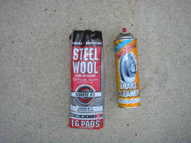
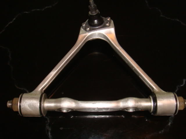
I’m currently cleaning up the upper and lower A-arms and front knuckle so that I can replace the ball joints with new units that I ordered from Corvette Central.
Here's a few shots of the one side that I've completed and the other side that's waiting for a bath .HUGE HUGE HUGE difference and really doesn't take much to get this stuff clean, especially with the steel wool pads.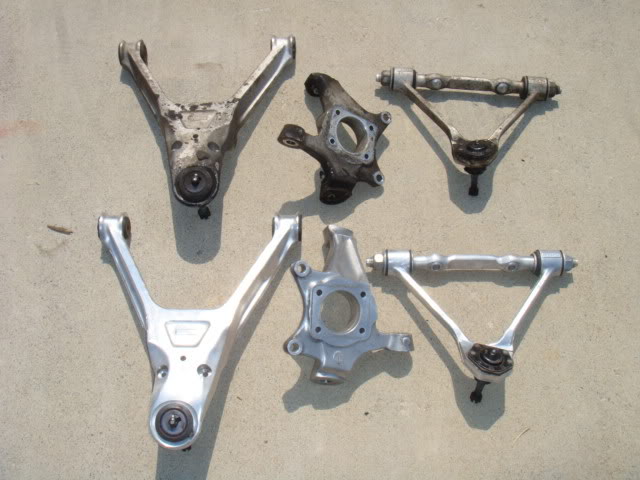
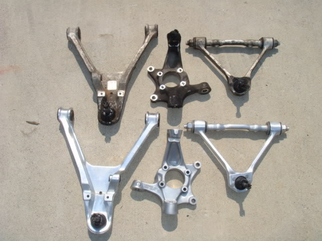
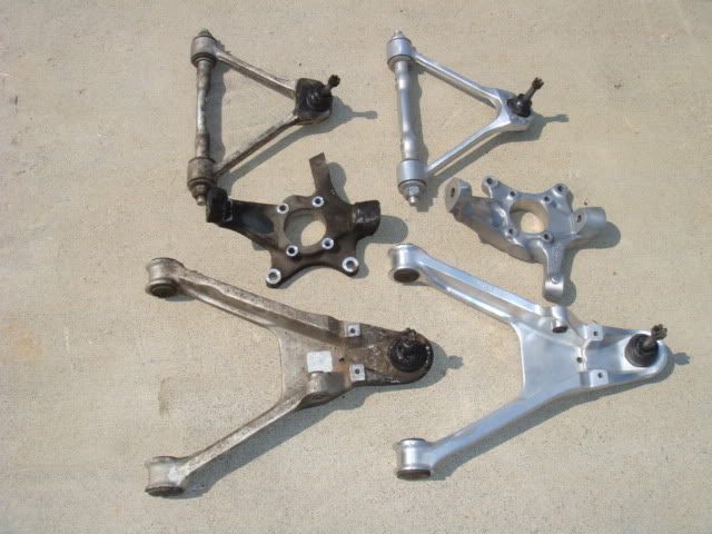
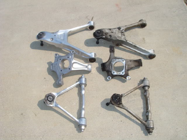
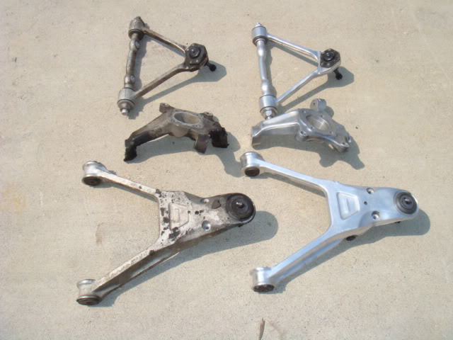
I was going to go with the full blown polish it til it makes you cry shine, but realized that with the way I'm going to drive this thing, it wouldn't last long at all. Too much effort for a non-show car. So I'm doing it right to clean it up and hopefully will be able to stay on top of the natural aluminum and not have to deal with metal polish day in and day out. Even with the steel wool and brake cleaner, the metal shines pretty nice and is a HECK of alot nicer looking! Enjoy the pics
6-8-2008
Well today I went to pull the front spring out of the car. Not a hard job, but I do understand why it's so important to get the car high off of the ground. If the car isn't high enough, the curvature of that spring will leave you stranded. Lucky for me, I had my car up high enough to help with the removal of the tranny prior to the motor pull so it worked out well.
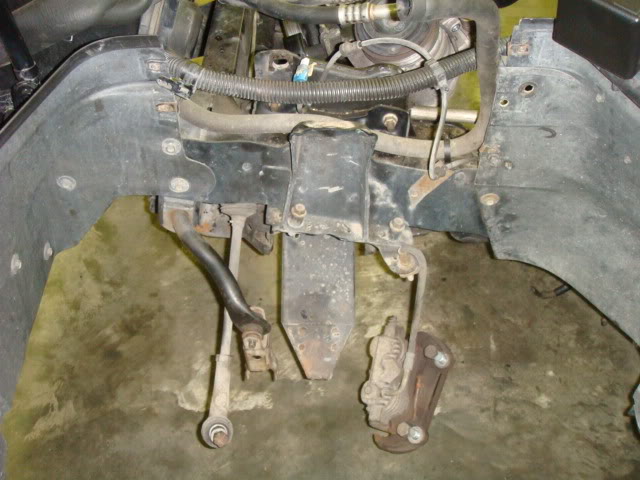
Here's a shot of the car without the engine, spring still in place.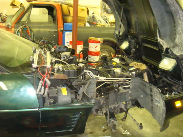
Here's a shot of both sides of this dirt monster as she sits right now.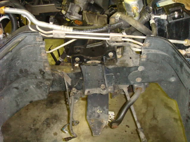
An underside shot of the spring in place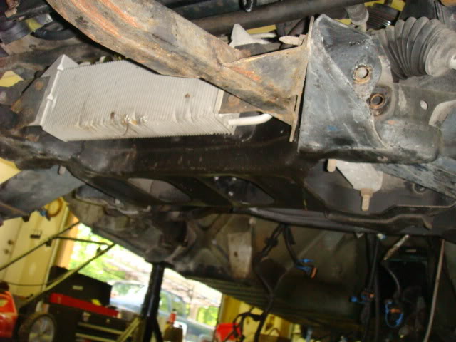
And a shot of the spring retainers just before I losened the four 5/8" bolts and dropped the retainers.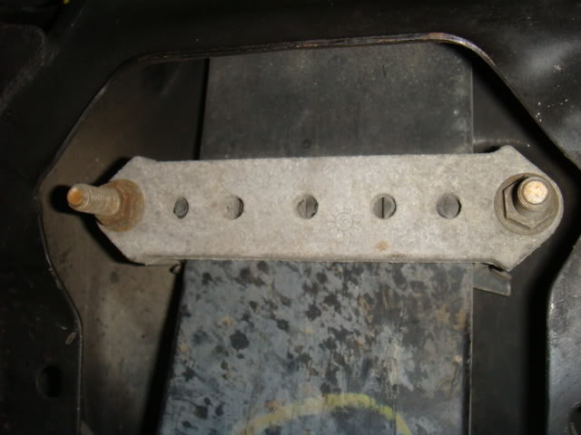
Once I got all four bolts out, the rest was easy. I just picked a side and carefully pulled the spring out from the chassis. It sits in a channel, so be careful not to ding or damage the spring.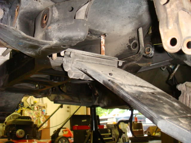
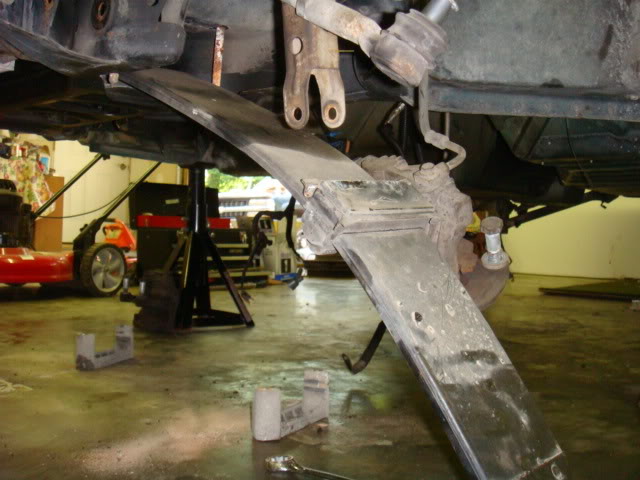
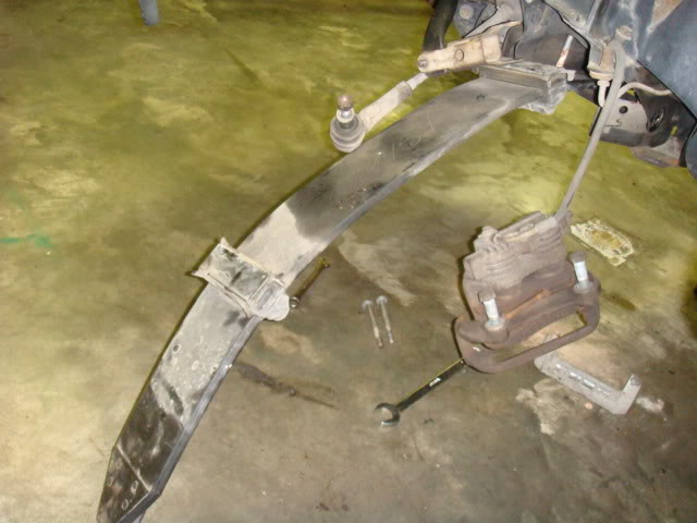
And here she is, out of the car sitting on the ground just waiting for a good cleaning and some lowering pads.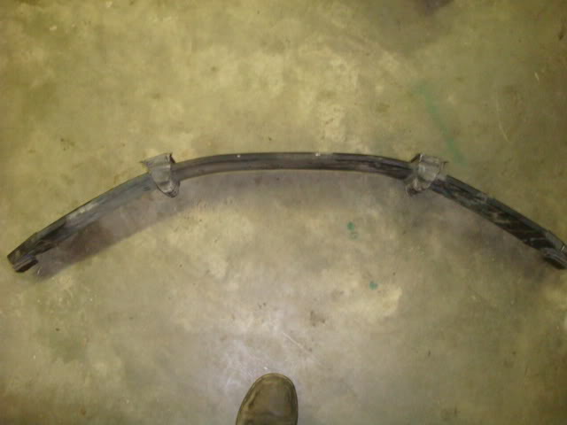
While I'm at it, here's the suspension kit that I went with for this build.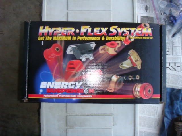
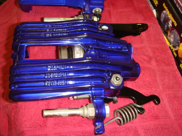
I also found a VERY good powder coater in my area that I have these Red Z-06 calipers to, and ordered new brackets for this build. The rears are the ones off of my 91, but since I didn't want to wait, I had him powder coat all of these peices for me. Oh yeah, did I say it was going to be a Grand Sport Replica?......LOL
Front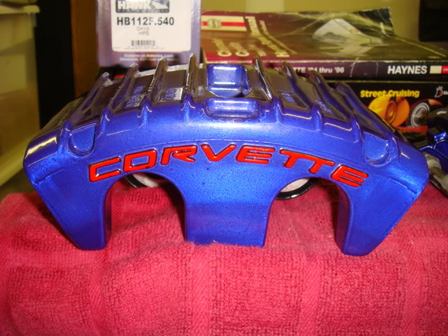
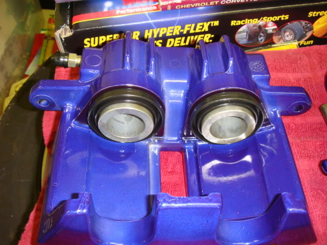
Both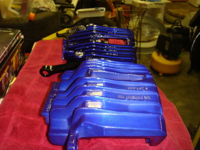
Rears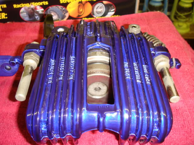
Brackets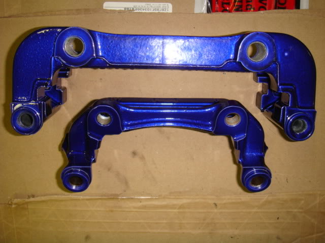
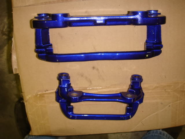
There ya go, I'm going to pull the power steering, clean it up and replace the bushing on that next weekend right after I push it outside of the garage and power wash all of this crap out of the engine bay and the rear end. I should have the wedges installed and curing this week. I'll post pictues of that once I get that going. Disassembly of the rear suspension should be next weekend as well, then I'll start putting all of these pieces back together so that when Will is done with the motor, that'll be the last thing that I'll need to do. Thanks again.
6-9-2008
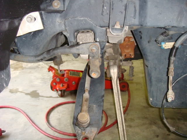
So I have a stuck bolt which welded itself to the front right swaybar endlink. I'm in the process of cutting the bolt off, but was wondering if there was a better solution to the cheap-O stamped steel piece that Chevy put on these cars? Someone mentioned Heims Joints or something like that before, but is there a replacement part that keeps the rubber bushings, or am I stuck?
Here's a pic of the bad endlink still attached to the sway bar.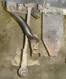
6-14-2008
With help from Rob (BlueWasp), we went to tackle the removal and replacement of the front A-arm upper and lower balljoints and bushings. When Rob informed me that we probably wouldn't get through both sets during the night, I thought he was crazy. LITTLE did I know how Crazy I was. I thought that there was no WAY, with all well setup shop that he has in his house, that it take long to pop the old out and drop in the new. Needless to say, this job is ALOT harder than I would have ever imagined. Either way, here it goes!
Here's the Upper A-arm before we started the removal of the upper balljoint.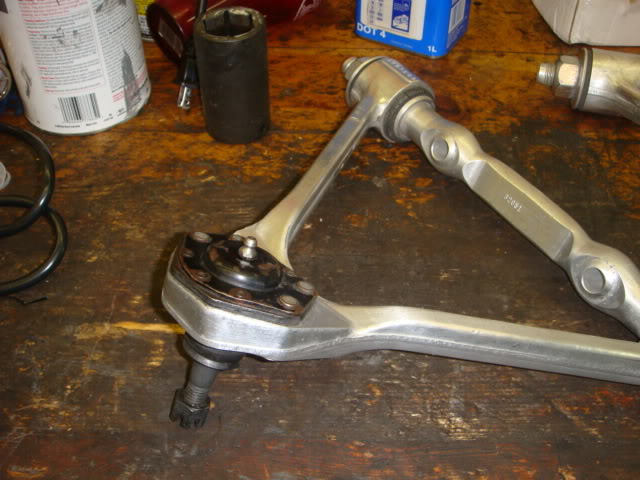
This was followed by the grinding off of the rivet heads.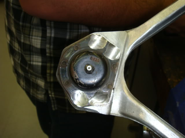
Next came a center punch mark and the drilling of holes in the center of the rivets down ~ 1/8".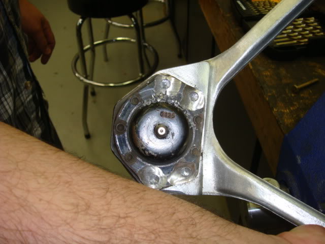
After that step was completed, a air hammer was used in the rivit holes to knock the ball joint rivets loose from the top and unseated the rivets in the A-arm. We then took a screw and pressed the rivets out from the top of the A-arm.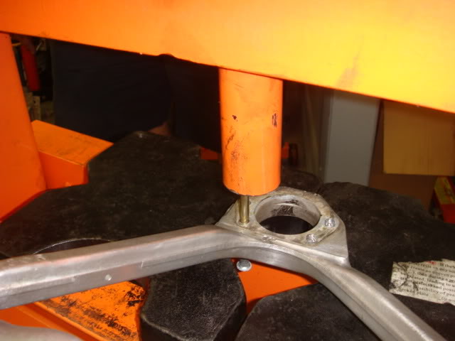
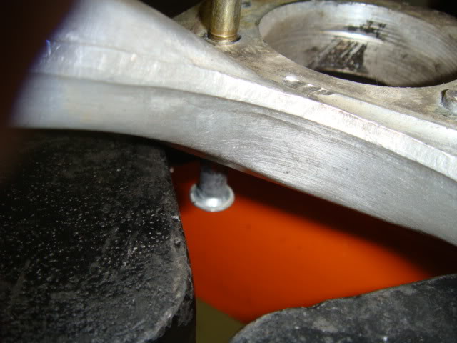
And this is the completed piece.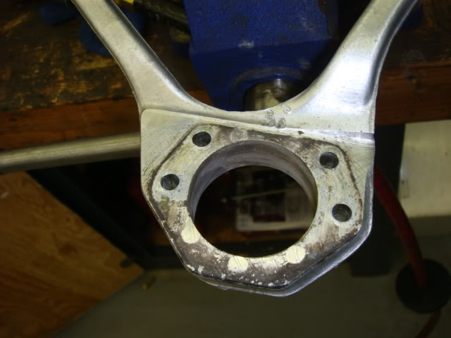
I'll post the bushings and lowers later!
Thanks and I'll keep it going as long as I can!
Next came the nut removal..........The thing that shocked me was what it took to get these off. I had tried eariler to remove these with hand tools at home, then I figured it may require air. Neither assumption was right because it requires heat....and LOTS of it! Not only do you have to heat up the nut in order to remove it with a wrench, then you have to clean off all of the dark red glue-gunk which can only be done when it's hot and bubbling.
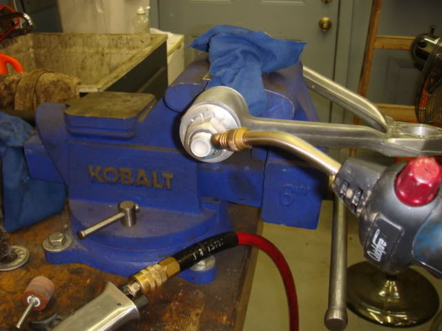
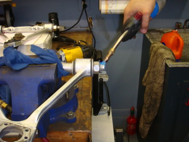
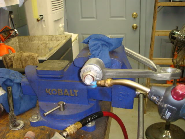
Once the dark red glue-gunk is hot and bubbles form on the outter edge of the nut, a nice size wrench can be then used to remove the nut.
Here's Rob in action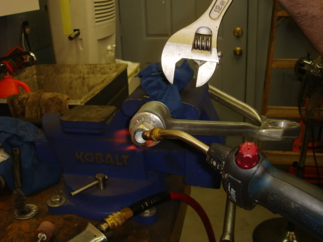
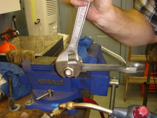
After the nuts have been removed, I used the vice and more heat to clean up the excess dark red glue-gunk off of the threads of the nuts.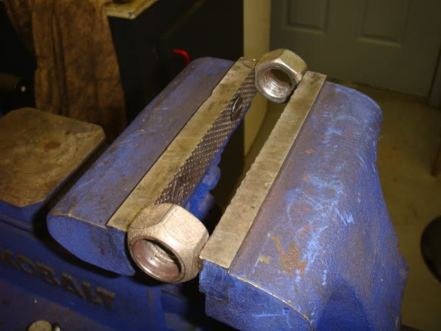
We used the press to remove the bushings from the upper A-arms one side at at time. Just be careful not to use a press that's smaller than the hole in the A-arm. Rob used a socket and it pressed through like butter.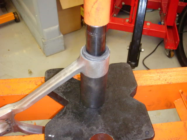
Getting the lower balljoints out was much easier than the uppers. This is the stock lower balljoint and notice the small metal tab on the bottom of the joint. It needed to be removed with a grinder in order to get the press fitting to fit over the outside diameter of the balljoint for removal.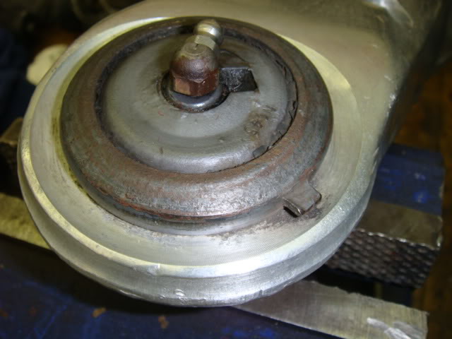
Here's a shot right after I VERY CAREFULLY grinded away the tab without damaging any of the Aluminum A-arm.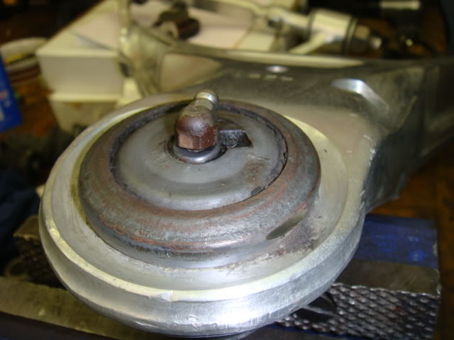
Once that was done, the rest was a walk in the park. Just setup the press, use a fitting that fits over the outer rim of the ball joint and press from the top down.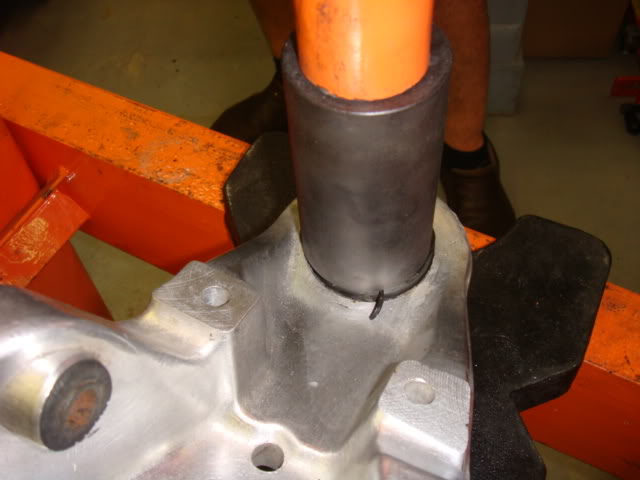
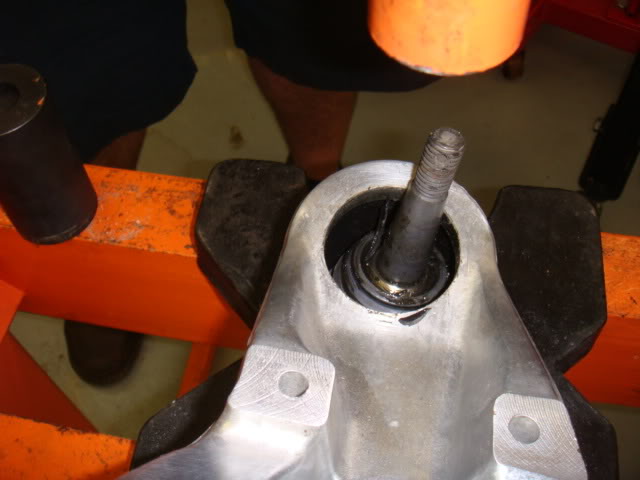
Once it was out, minor clean up and a nice coat of grease put us to a place where we could install the new balljoints. Here's the setup as we started the install.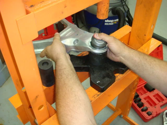
And this is where we stopped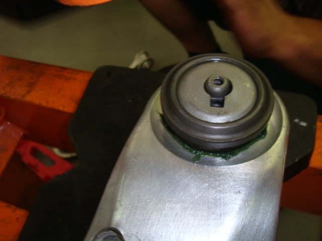
I have now realized that my experiance with the Corvette America Balljoints are just like other's on here that have seen these oversize bodies. SO, Now I have to figure out what I'm going to do, but the words MOOG seem to be sticking in my mind right now. I REALLY Wanted to save a little dough on this, but I'm just not willing to deal with anymore crappy part setbacks like this again! SO, LET ME STATE THIS, PLEASE AVOID THESE!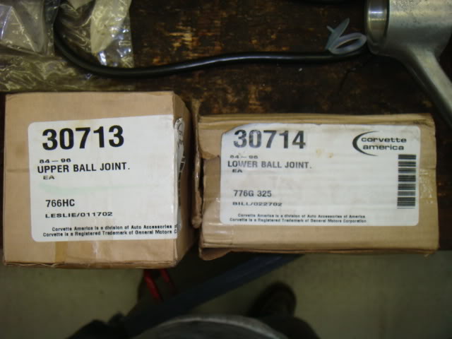
Oh yeah, and it's NOT Just their Lower Balljoints.............Let me show you what the Uppers looked like when I went to install them.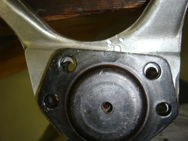
So I tried a different angle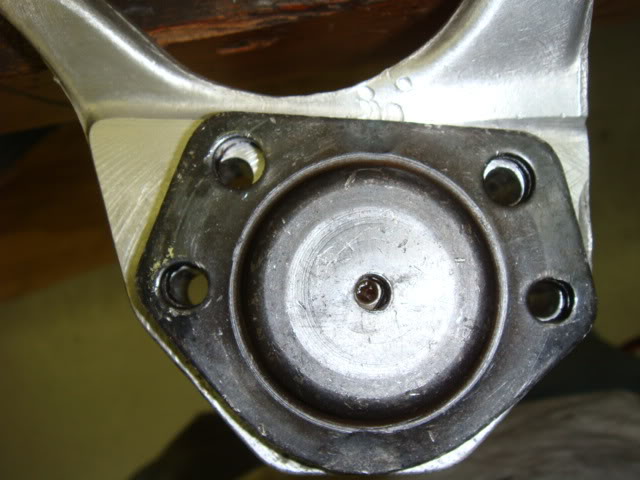
SO, As you can see, these crappy balljoints just did NOT work in my setup........Maybe your results will vary but I'm calling them today and getting them straight AND My money back for this crap! NOW, since I was stuck and could not make anymore headway with the balljoints, I moved on to the bushings and pressed them out of the lower A-arms.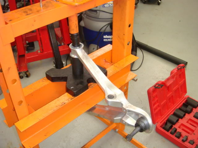
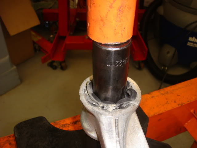
Well, that's where I'm at right now and I'll update more when I get it! Enjoy and a HUGE thanks to Rob (BlueWasp) for helping me out!
6-15-2008
So I open up and take a closer look at my Energy suspension kit only to find out that there's something missing and just not right.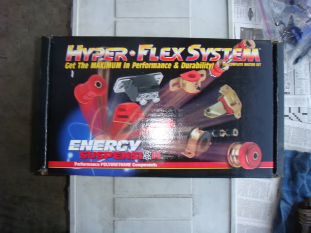
Here's this particular part of the kit with that should be a complete front end kit minus the bushing for the sway bar.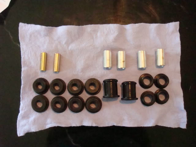
The first thing I noticed was there there were only two sleves for the lower control arm ES Part# 15.10.126.39, vice 4 as called out on the master list.
Then I noticed that I only had seven ES Part # 3130 lower control arm bushings and one 3068-3. I tried to look on ES's website and there is no listing for a 3068-3, but that's exactly what I recieved in this kit.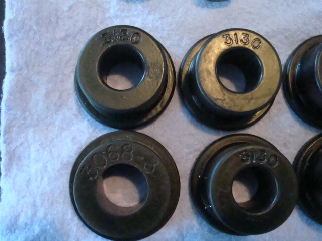
Here's a closer shot of the unique bushing so that you can see the difference from the 3130's.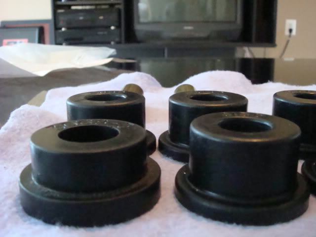
I'll call tomorrow and straighten this FUBAR out! The good news is that all the other components are just as ES stated except for my rear strut rod set came with all of the components of the Set number 3-7107 plus four of the 7024's from the 3-7108 set. This basically gives me both the 3-7107 and 3-7108 in one package. I'm sure this is to cover all of the bases on the 95-96 Corvette. That maybe due to this set only listed good up to 95, and there is no number for the 96.
6-22-2008
So after the problems with the previous ball joints from Corvette America, I was looking to order all MOOG units, but decided to call around to the parts stores in my area first. I wanted to find something close and stumbled upon TRW brand ball joints and tie rod ends. Since I already had close to $200 on a store gift card, AND the TRW's come with a limited lifetime warranty it was pretty much a no-brainer. So I paid the difference for the TRW upper, lower ball joints and inner tie rods. One of the first thing I noticed about them is that they look very similar to the MOOG units, and completely different than the ones I received from Corvette America. I know understand how I can use the rubber boots from my Energy Suspension kit with these heavy duty, well constructed units. So I sent up the Wasp Signal and setup an emergency meeting at the Wasp Cave!......This is what the TRW ball joint looks like for the lower.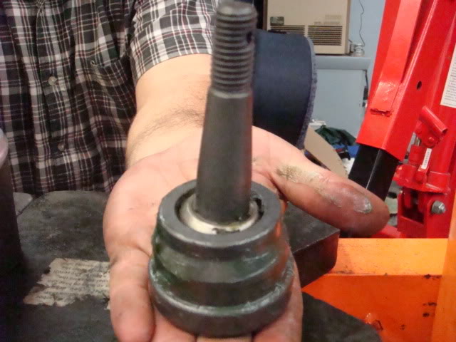
So we started the process again, I was very leery about how it was going to go, but these units went into the lower A-arms like butter.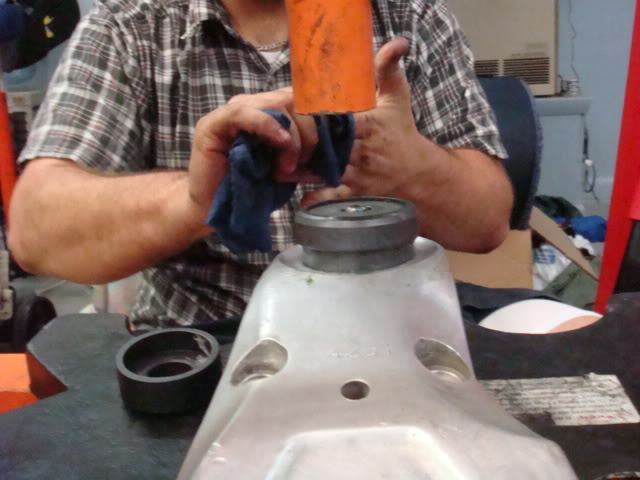
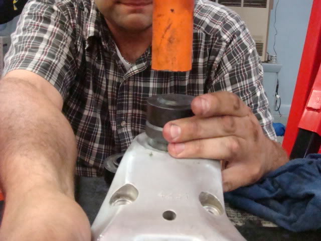
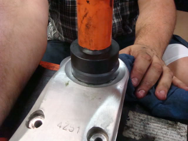
The upper A-arm ball joints were well constructed by TRW as well. The holes were slightly elongated in order to facilitate proper alignment during installation. I used red loctite and the new ES urethane boots on these. The tricky part with the upper A-arms is the installation of the new bushings. In the instructions it tells the installer to use a brace to keep the arm from flexing during the bushing installation. We used a 3/8th socket extension and a small metric socket in order to get the proper length and it worked like a champ. The installation of these bushings were the most difficult, because of the finessing required in order to have all the right bushings just in the proper location and to get all the planets and stars lined up in order to get the bearing press event to go smoothly. Either way, here's the setup with the support rod.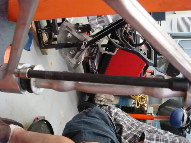
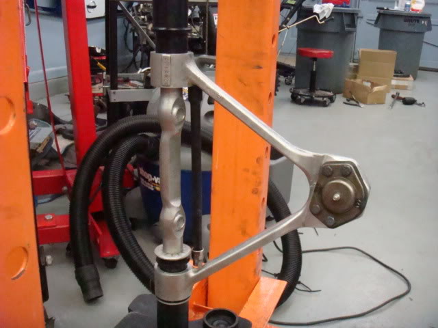
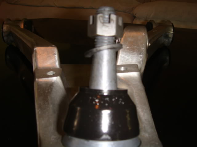
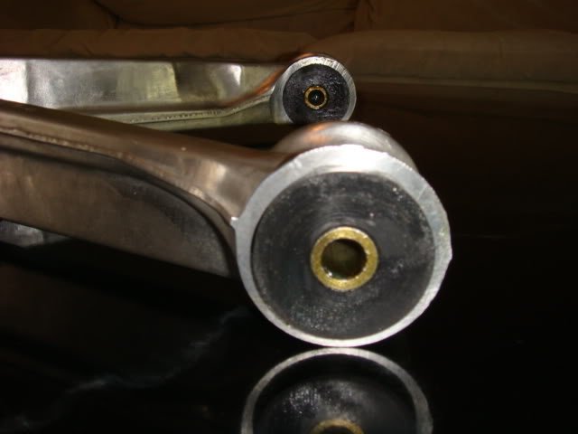
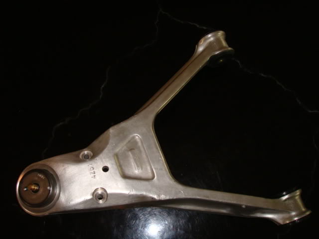
And finally, here's a few pictures of the finished product, new ball joints, bushing, sleeves, cleaned and all greased up and ready to be re-installed back on the 96.
Lower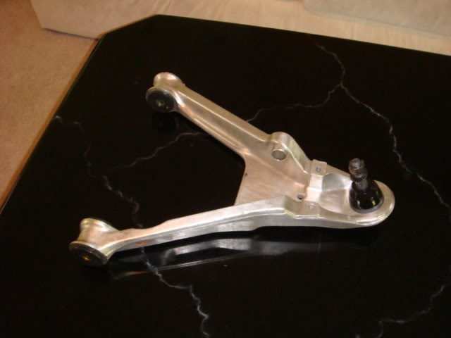
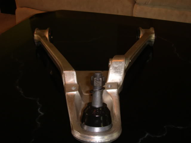
I'm waiting for my ES swaybar bushing set, but as you see the old dried out and cracked OEM pieces have been removed with this area cleaned and prepped......ready to go.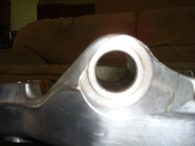
Upper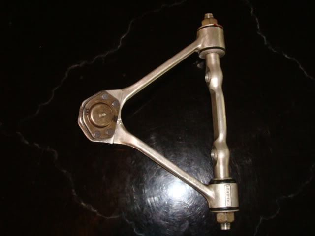
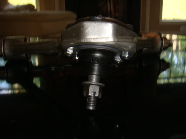
You'll notice that I installed the upper ball joints with the nuts towards the bottom, not the top of the a-arm as described in the service manual and instructions for the upper ball joints themselves. I took BlueWasp's advice on this, as he's been down this road before.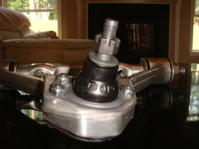
Complete with new fresh red loctite
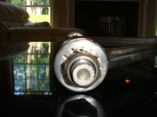
The slight discoloration on these nuts are from the torch used to remove them due to the factory red loctite (not sure exactly what, but similar) used during factory installation.
I'm currently working on removing the bushings and inner tie rod's from the steering rack, and cutting the rubber off of and installing new lowering wedges on the front spring this week. I also began the disassembly of the rear suspension as well. I did notice something that I'm going to have to take care of, and that's new seals for my D44.
In this picture, if you look closely you will see, just slightly right and lower of the yoke (rusty orange).
This is who knows how many years of gear oil leakage from the diff. Since I'm this far into it, it is not going to be much of a problem to replace all of the diff seals and it's a fairly easy job to do.
Thanks Jeff, and just to let you know I STRONGLY believe in the TRW as a great alternative to the MOOG. And here's my thought pattern as to why:
1. TRW ball joints run anywhere from $20 to $30 a piece lower than the MOOG.....PER BALL JOINT! (~$80.00 and up for a full set of ball joints)
2. The TRW's came with a warranty, and I did not get the full skinny on the MOOG's (I was under the impression that upon my purchase from RockAuto, I was on my own), but they may or may not have the same fine print.
3. The TRW's were right around the corner from my house, in stock. I would have had to wait two to three days for the MOOG.
4. I've done some homework, and I have yet to hear many negative comments about the TRW. Their manufacturing spec is very close to that of the MOOG, and better yet THEY Have a spec!.....LOL.
5. I’ve been looking for a ways to shave some of the cost on this project, yet keep quality parts. I went the TRW route and I believe that with the LL warranty, I'll be OK!
Thanks for the support there Jeff, and since I am working 3rd shift this week, I'll have time to get those bearings shipped off to you.
6-23-2008
I was able to get the Pumpkin and Batwing out of the car today. This is the last of the suspension disassembly, so after I get all of the old bushing pressed out this week, this weekend should be re-installation of the suspension. I discovered that I have a leaking seal on the passengers side-yoke of my D44, so I'm going to replace all of the seals and be done with it. I also discovered that my rear tie rod assembly is crap so I'll need to get a new one of those as well. I can't find one for a 92-96, but I was under the impression that they were all the same. I have more investigating to do on that issue.
Here's what the D44 looked like after I removed the rear spring, there was gear oil and crap all over this. I had just started to clean it with a power washer as you can tell by the left side of the batwing as compared to the right, which is still dirty.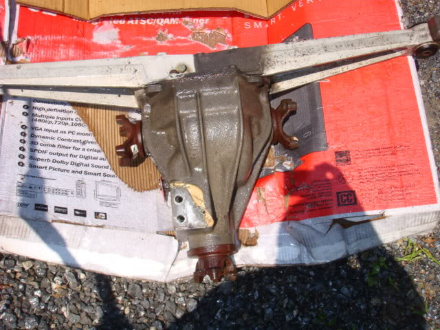
Just another shot after cleaning part of the right batwing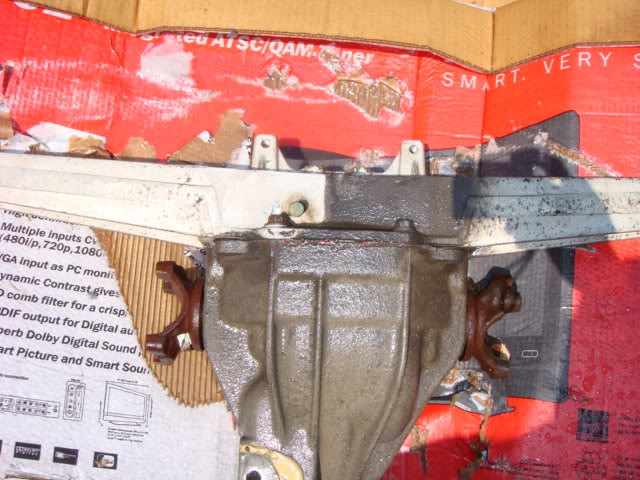
Here's the clean batwing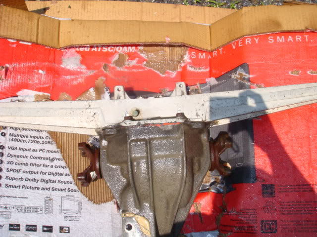
And finally the pumpkin after I hit it with the Power washer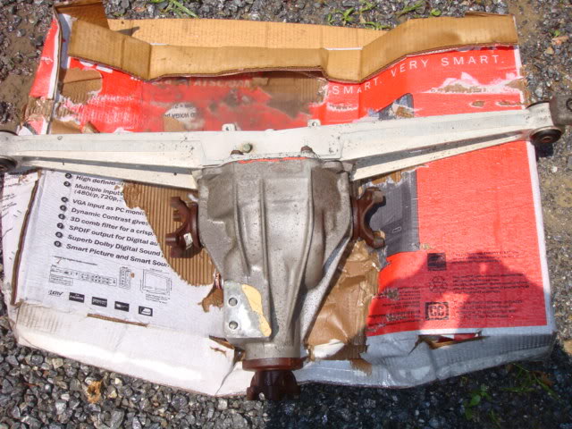
So now that I got most of the junk off of it, I have pulled the Batwing cover so that I can press out the bushings and I have to break out my steel wool pads and brake cleaner to make these pieces look the way that they should.
Thanks for looking, more to come.
Thanks Jonathan, as far as the Gobba-Goop goes, when I replaced the seals on my 91 D44, I didn't put more G-G on it. I just bolted the Pumpkin back in and used loctite on the nuts. I"ll check my FSM tomorrow and see what it says about the stuff, I'm not sure about the specifics, but it may have been used to either prevent rattling, or to hold the C-beam in place during the torque and assembly at the plant. If anyone knows, please feel free to chime in! I know that you can get C-Beam plates to put in and I don't remember that CF member that was selling them saying anything about the G-G during installation. My 91 is still doing well after three years of me replacing the seals in it.
R/Noland
P.S. Jeff, it seems like the more I took apart the more crap I found wrong!.......LOL. BUT The cool part is that now everything is off and I can start putting things back together now!
6-28-2008
I located a set of beam plates that I'm pulling the trigger on Monday. As far as the rear suspension goes, it was TWENTY times harder getting these components clean, than the front setup. I still have the rear knuckles and trailing arms left, but here's what I've got so far.
My Energy Suspension swaybar bushing FINALLY made it, after over a months wait.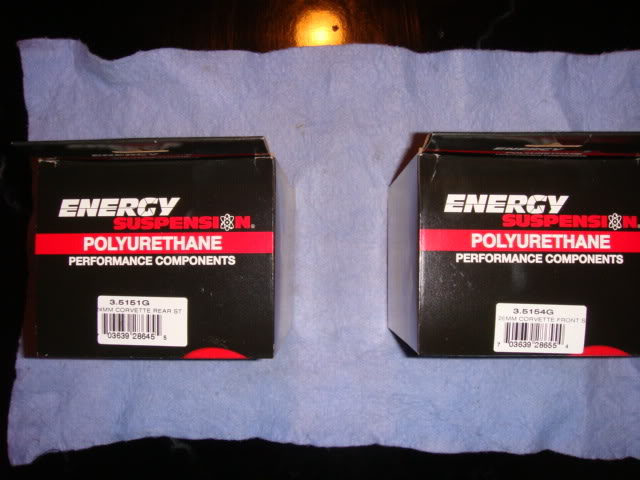
And one of the first things that I noticed about them is that the bushing for the lower A-arms on my 96 required me to remove the sleeve that was pressed into the A-arm. It was no easy task, but required a hacksaw blade and patience as to not saw into the aluminum A-arm. The bushing has a molded angle which allows it to fit into the swept angle of the A-arm once installed.
Here's the sleeve still installed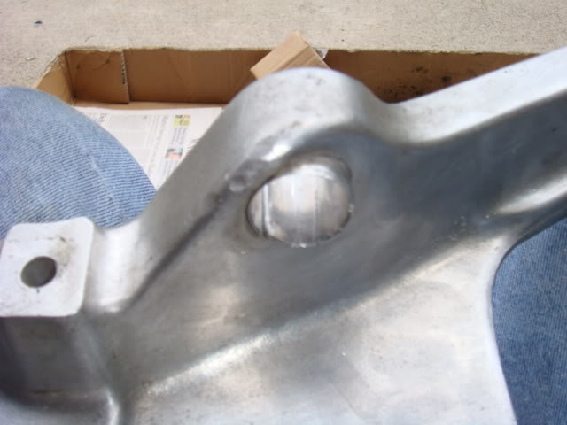
Finally getting it to back out
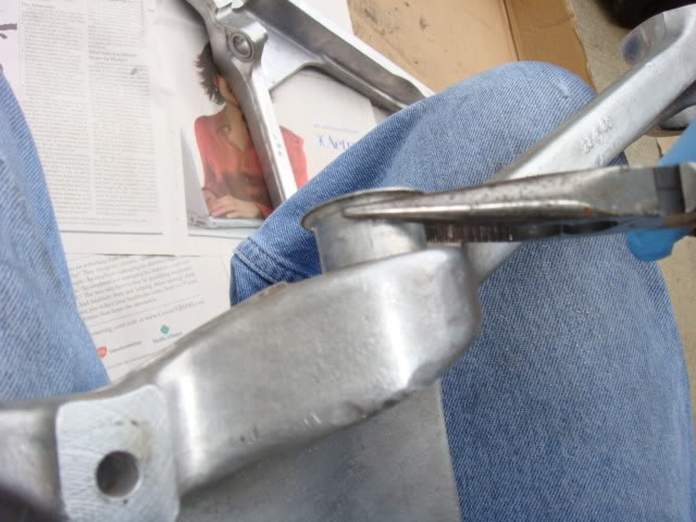
The sleeve removed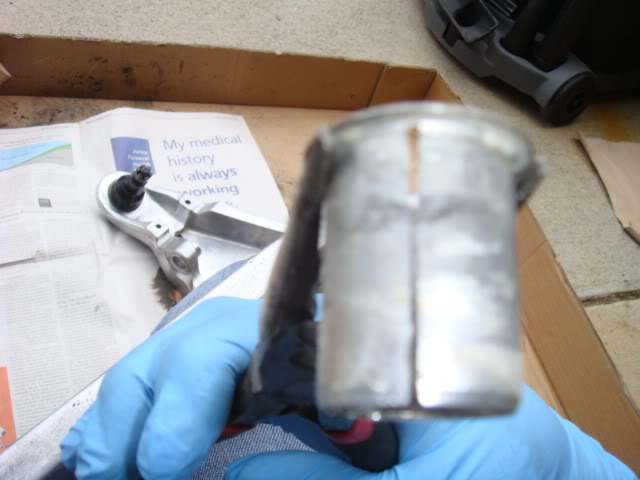
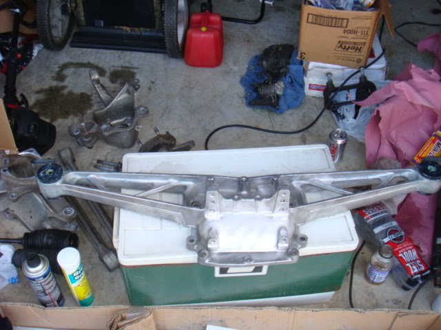
I also had to do the same proceedure with the batwing sleeves.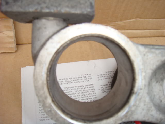
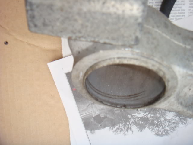
This is what it looked like once I got the sleeves out of the batwing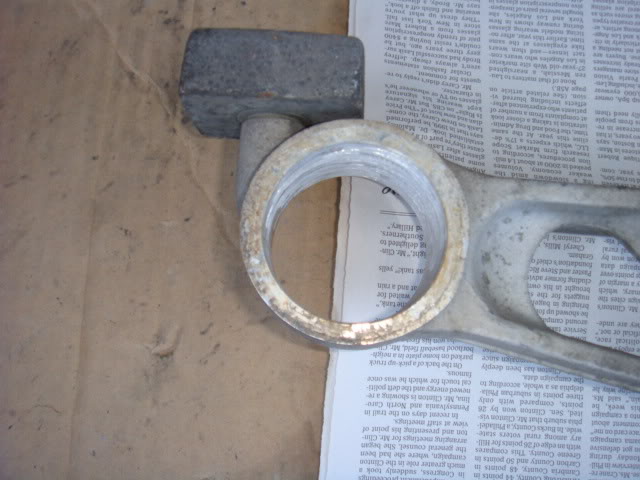
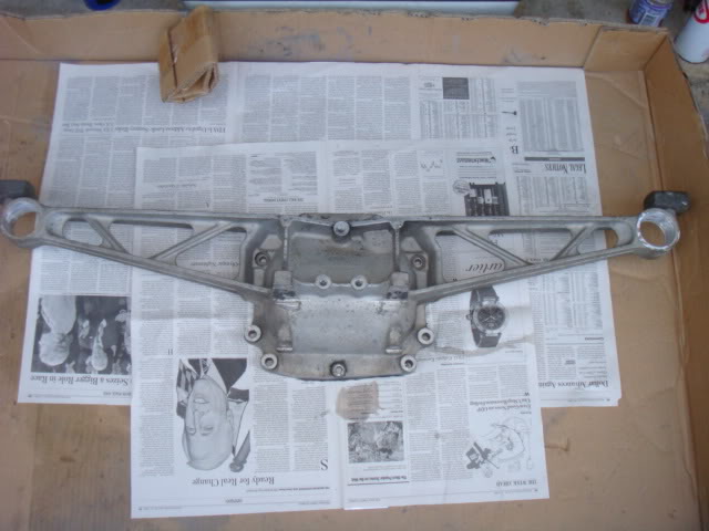
My next task was to clean up the batwing and make it look good, it's hard to see due to the lack of lighting outside at the time, but here's the cleaned up batwing.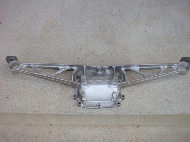
And here's the new bushings installed and all lubed up.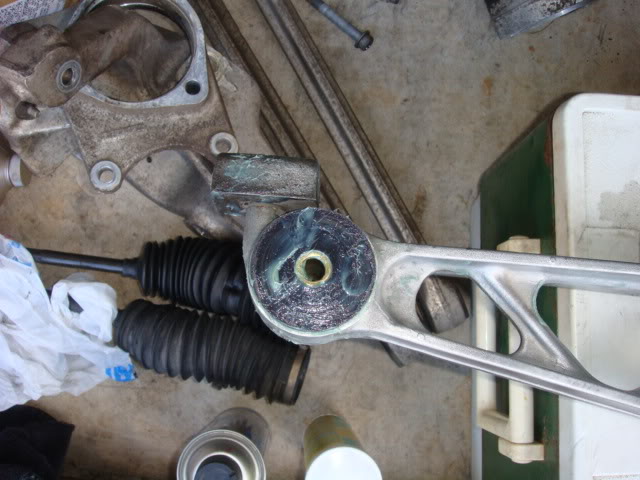
Ialso took on the dogbones, I'm not sure what was used in the installation of the bushing, but it left a residue that I had to dremmel out of the internal areas of these. Once I took care of the inner caked on crap, I then started working on the dogbones themselves. I tried to tackle these like I did with the front suspension pieces but I had to use a drill with a wire wheel to get these properly cleaned.
In this shot is the before, brake cleaner and steel wool and finally the wire wheel. There's a huge difference between the three.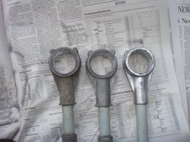
Here's a shot of the completed dogbones once I was all done. Bushings installed and all greased up!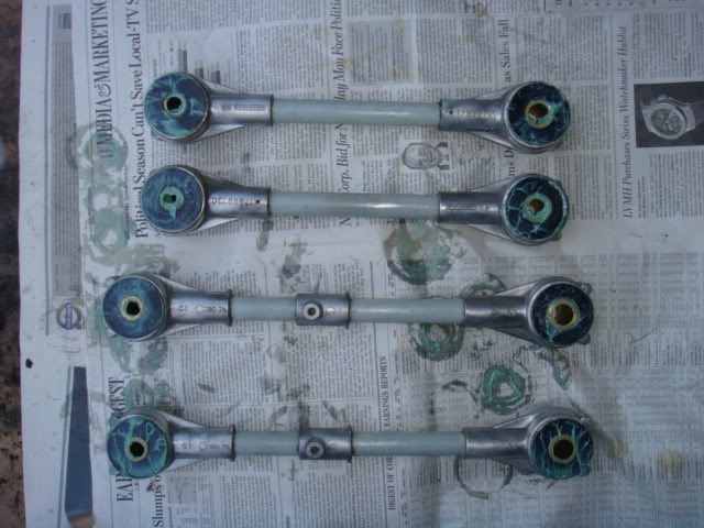
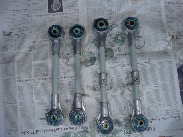
I hope to finish up the rear suspension peices tomorrow, thanks!
6-30-2008
Your very welcome and I tried to finish off the last of my rear suspension pieces today, but even after taking off of work, I still have to finish up my half-shafts and clean up both side and driveshaft yokes. I am unaware of any special requirements of the Poly's over the normal rubber that came on them. I do know that you have to lube the crap out of them during installation to keep them from squeeking and I've done my best on all of them to prevent such an event! I'll look into it and see what I can come up with, but I think it's during install only, unless you do some crazy type of clean up re-fresh job after XXXX miles or so. I've never heard of that though.
I was able to get the front swaybar cleaned and painted, due to it being too large for my powder coater to get in his current oven. The rear knuckles and all of my other pieces are about ready to go, so HOPEFULLY this weekend I can start re-assembly. I have to do some touchup painting in the engine bay and on the front end, but other than that the rear seals for the D44 are in so I'll install them and hang the rear end and start to torque away! More pictures soon!
7-17-2008
This afternoon I dropped off the new drive shaft and freshly powder coated transmission yoke at Driveline Specialties in Lorton VA. They are performing a dynamic balance of my drive shaft and he recommeded that I not balance the half shafts as in it wasn't necessary. When he inspected my yoke, he informed me that I needed a new bearing, because the yoke was showing signs of wear. SO, Now I'm getting a new bearing and seal for the tail of my ZF-6. I was also informed by PDQuick that I should replace my clutch pack in the D44 since I was this far into the build.
Here's what showed up with my order for the clutch pack.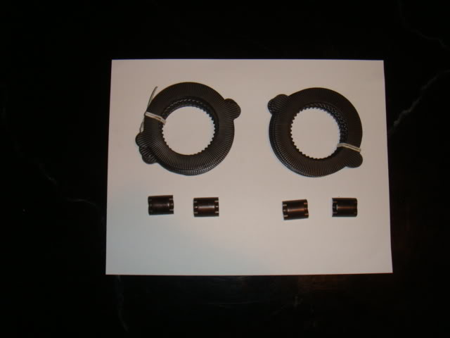
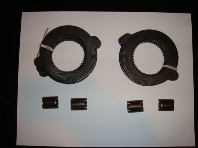
I pick up the driveshaft tomorrow and with the exception of the beam plates am pretty much ready to start putting this thing back together. I still have to pick up my last peices from the powder coater. (Halfshafts, D44 bolts, u-joint straps, ect...) but it's moving.
7-25-2008
So I THOUGHT I was ready to put things back together, right until mseven posted pics of his rearend. So because of that picture this is what happened.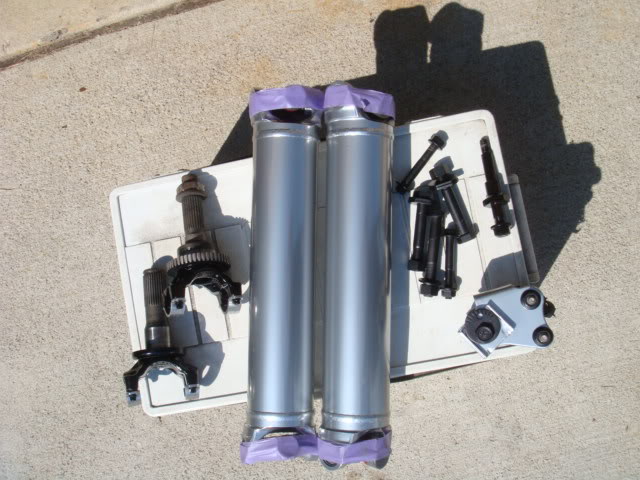
So here's better detail of the various pieces that I had done.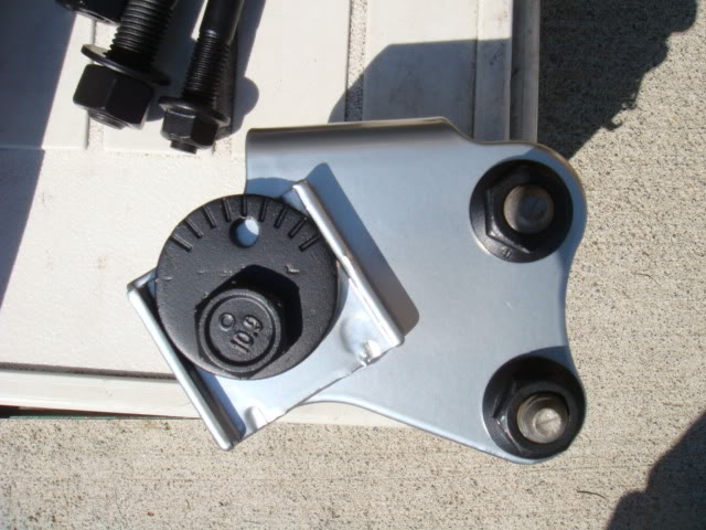
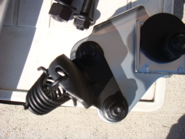
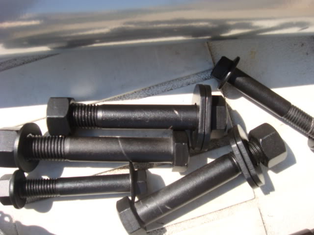
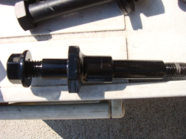
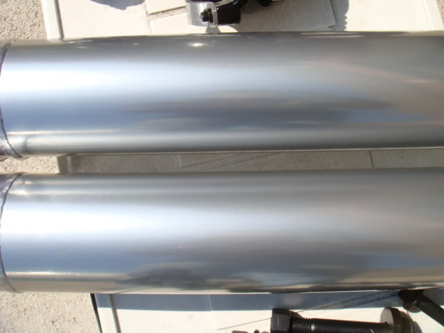
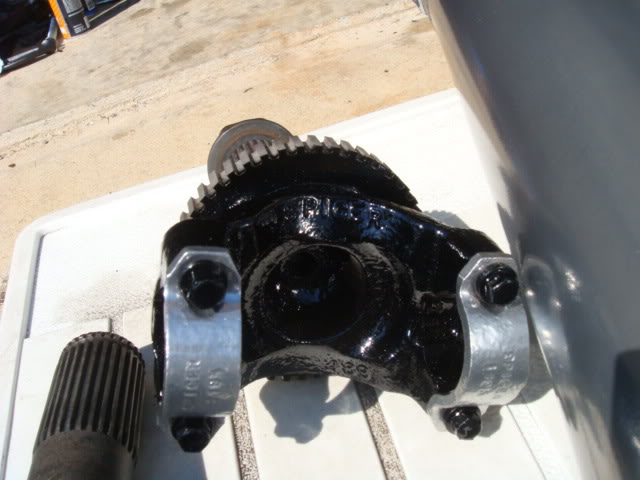
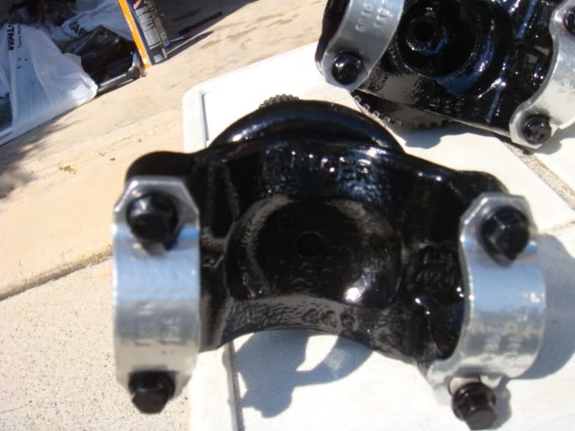
NOW I'm ready to put the suspension back together!
I had a hard time trying to get through the removal of the rubber from the front spring. I finally found out that the best way to cut it off is with a normal woodsaw and WD40 as a lubricant. The problem with that is once I was done, the rubber was jagged and not smooth or close to the spring. I did a search and one member used a belt sander to sand down the wedges to make his car sit lower. SO, I used the a friend holding a belt sander on a work bench, while I manuvered the spring to sand down the rubber. Before I did that, I put tape on both sides of the rubber to ensure that I didn't sand the spring or cause any damage. The tape would also act as a warning device that I was getting too low. This is what the finished product ended up being.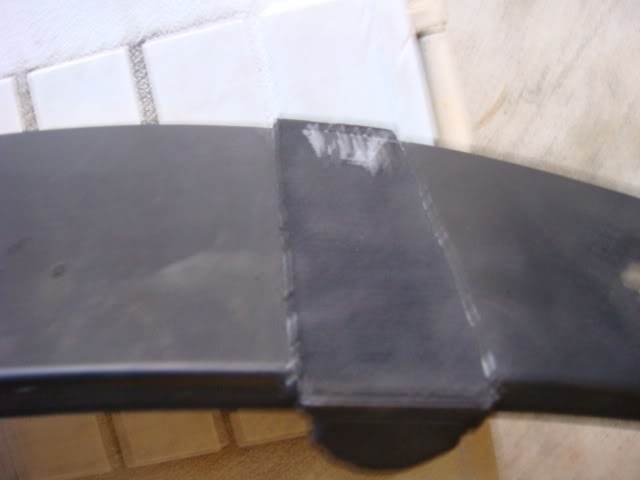
Here's a side-on shot of it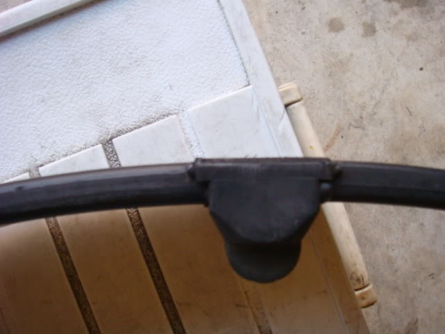
Needless to say, I was VERY happy with how close to the spring I was able to get the rubber.
The other thing that I did was to cut off 1/2 of the rubber pads on the tips of the springs to bring me down just a tad bit more.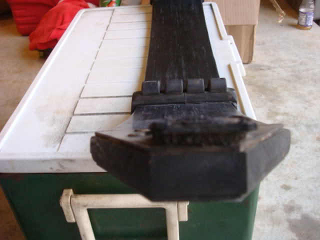
Another angle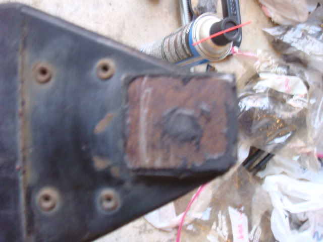
And because I didn't want metal to touch my lower A-arms, I came up with a simple solution to that problem. I took the strips that are called ABS shims, in my lowering kit and cut them to the length of the small end pad. I then taped three of them together and glued them to the tips with a clamp just as I did the wedges.
Here's the glue that I used for my spring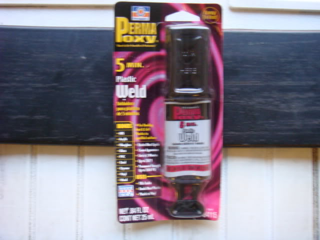
And here's the spring setting up with all wedges in place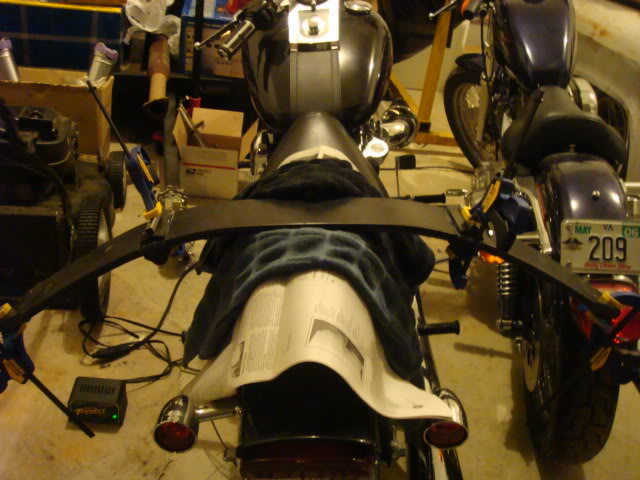
And last, but not least, these showed up at my door.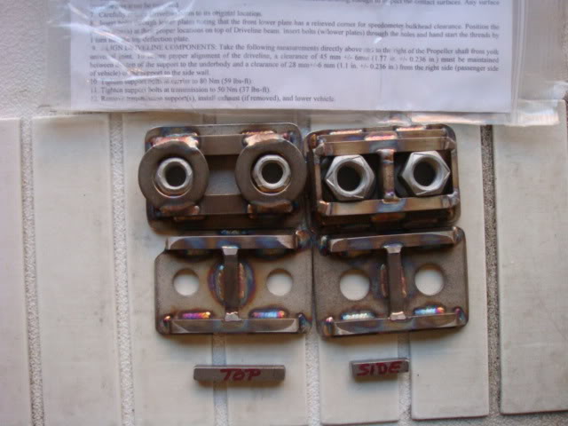
Noland
P.S. Steve, I AM going to use the 4.09!
Thanks Steve,
Here's the results of my front spring and lowering wedge installation. I also took pictures of the shims that I used to protect the lower tips for the extra few mm's of lowering.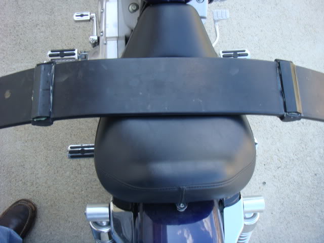
Here's the tips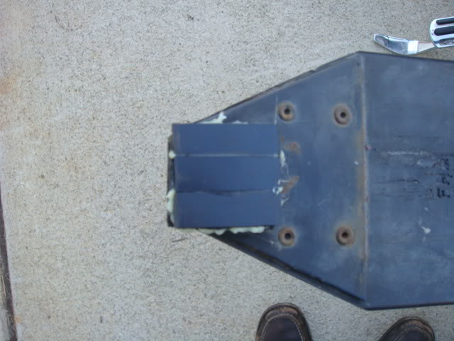
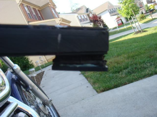
And a better shot of the wedges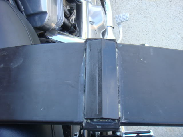
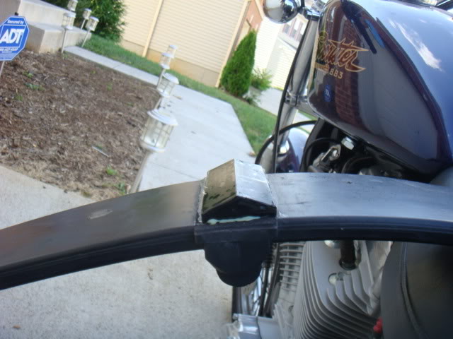
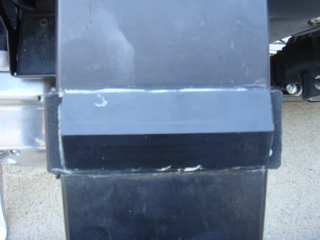
That's the spring, all cured and ready for install. I actually took care of my painting up front, and just need to finish up my wheel wells before I start putting this stuff in!
It's been AWHILE since I've updated the post due to me coming close to the end of this journey. I still have a few remaining things but my absence has been due to all of the remaining issues/problems/items that needed to be done. SO here we go. I'll update with HOW i got here later but just to show where I'm at now, here's a few pictures and I'll elaborate as needed.
I used Reflectex for the tunnel with 3M Super Spray on glue, worked like a champ!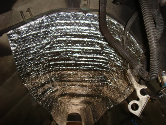
Here's where I was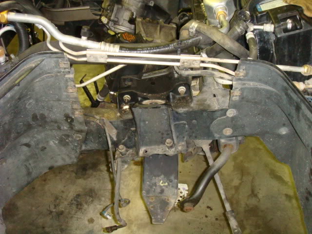
And this is it in progress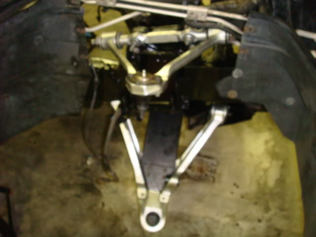
Almost done, need to get the proper spacers to install my front Rotors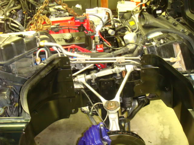
Rear before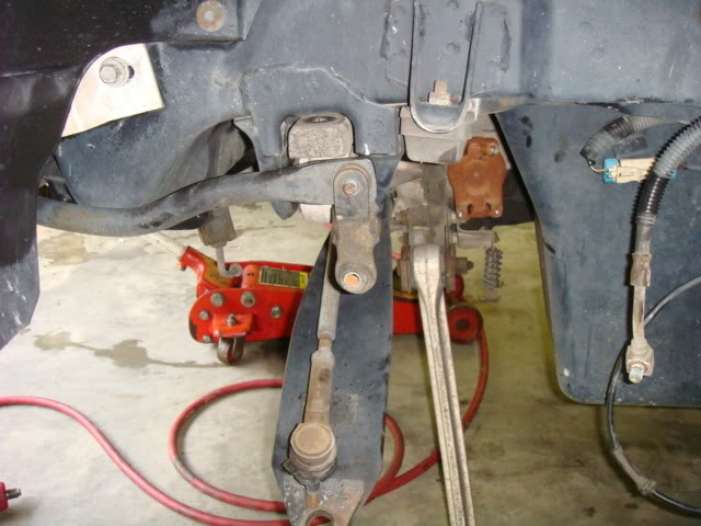
Rear in progress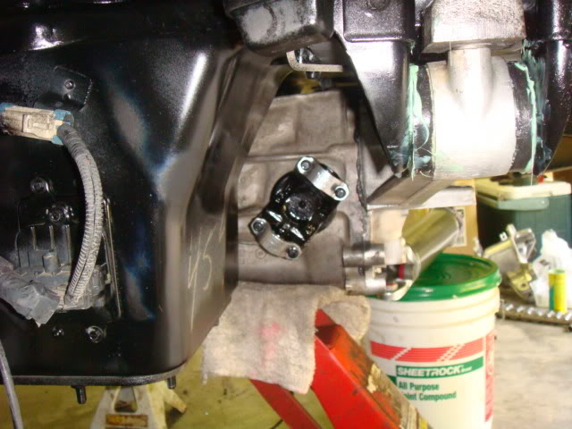
Another rear shot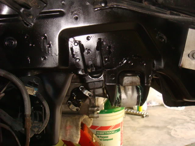
and another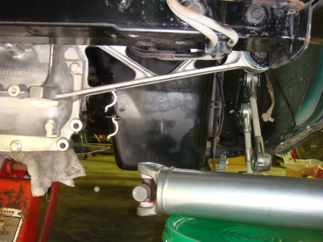
Beam Plate Installation, which was a PAIN In the A$$, it was VERY hard trying to align the C-Beam for some strange reason, but eventually I was able to get both beam plates installed and left loose with a jack on the tranny for aligning.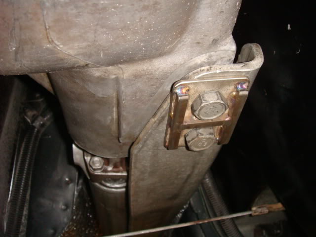
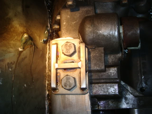
Now here's the beamplate alignment peices that came with the set of beam plates that I got from ZFDoc. If I had only used the set of beam plates that I got from Meryl of Exotic Muscle, I would have never known about this step in the proceedure. BUT here's the alignment pieces on the front beamplate, adjacent from the front yoke U-joint, at the side: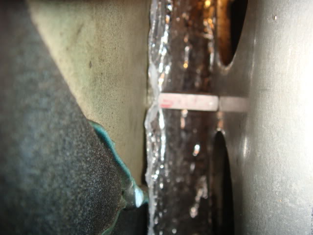
And the top: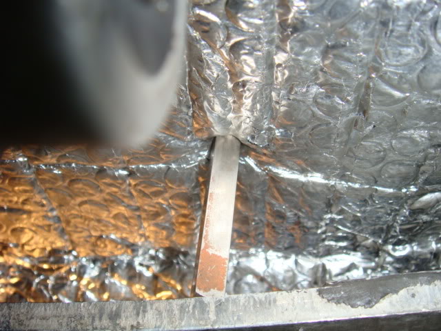
Then torqued to spec, I'm thinking it was ~ 37ft/lbs tranny and ~59ft/lbs D44, but don't hold me to that, I can look at the install sheet later.
That's it for now, going over to install the headers and try to finish this job out today! Thanks for looking and enjoy!
10-29-2008
Hummmmmmm, I can get some if you'd like!.........Not a problem 
Here's the alignment sheet!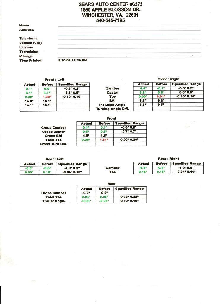
2-24-2011
The front end is basically lowered in a combination of one of two ways, or both.
1. The front spring pads are removed or modified in a manner to allow them to sit down further in the lower control arm. This can be done by completely removing the spring’s rubber spring pads, shaving the rubber contact area of the pads down or various parts of all the above in order to make the end of the spring sit lower in the lower control arm.
2. Modify the front spring cushion seat and spring retainer in order to allow the spring to sit up closer to the frame of the car. This movement of the front spring up higher in the suspension allows the spring to make contact with the lower control arms at a height higher from ground than the stock location. This is what the C4 front lowering kits provide. The installer removes the spring cushion seats and replaces them with the urethane rubber wedges and shaves the spring retainers down by the same measurement in order to lower the front end.
Now, there are other methods that can be accomplished as well as complete removal of the front spring to employ coil over shocks, but the above is for the stock setup.
I say the best way to tell, is to see if the spring has been modified, do a search on the Tech thread and look for lowering threads and see how the spring is altered, then compare it to your car to see where you stand. If you can remove the spring from the car, that would provide you the best method of determining what the condition and status of the front spring is (Given the assumption that your car has a front spring). Either way, good luck mission and your statement about your car being too low was the first time that I've ever heard that one.


Good pics!
Posted by Diggymart on 2/21/20 @ 7:34:22 PM