You must be logged in to rate content!
16 minute read
Acura RDX 2008 Front Strut/Shock Replacement DIY
Compliments of RangeRider49er @ https://acurazine.com
11-29-2012
Acura RDX (2008) Strut Replacement DIY
This is a DIY record of my experience replacing the front strut assemblies on a 2008 Acura RDX with new ones. This is not to be construed as professional advice and I am not a trained mechanic. If you attempt this job you do so at your own risk. You can be seriously injured and I urge you to be careful and consult professional help prior to undertaking this kind of work. This is an informational DIY only so that others may share my experience. If you have any doubts, seek help from professional mechanics.
Tools needed:
Hex head sockets of 12mm, 14mm (deep socket), 17mm, 19mm and 22mm. One 5mm Allen wrench on 3/8 inch ratchet drive or regular 5mm Allen wrench. Small width flat head screw drivers. Torque wrench and ratchet wrenches with 6 inch extension. Needle nosed pliers. Open ended box wrenches of 17mm and 19mm and a 17mm crowfoot. An impact wrench with 17mm, 19mm and 22mm (optional) impact sockets. Hydraulic floor jack and 4 jack stands capable of supporting the cars weight. Marker to mark nuts and bolts. Small blocks of wood to place underneath suspension when using hydraulic lift to raise suspension during installation of struts. U-shaped hack saw with thin blade and fine teeth! An extension magnet was also useful.
Parts needed:
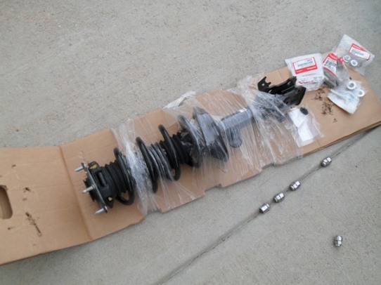
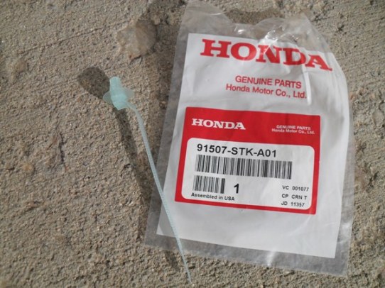
Left and right strut assemblies Part# 51601-STK-A07, 51602-STK-A07. Four flange (pinch) bolts #90119_STK-A01 and four flange nuts #90382-STK-A01. Two flange (stabilizer link) nuts #94050-12080. Ten flange (damper attachment, 5 each side) nuts # 90002-S10-000. Two sensor harness clips #91507-STK-A01. Anti-seize grease, white lithium grease and Super Penetrating oil.
You will need about four hours to complete this task if you have all the required parts and tools and assuming things go smoothly with no broken parts. A knowledgeable mechanic could probably do this job in two hours, maybe less! Here is a good diagram of the strut http://www.oemacuraparts.com/parts-c...shock-absorber . That link is to the dealer in Phoenix, AZ where I purchased the parts. They also emailed me copy of some brief installation instructions in PDF format. This was quite useful as it had the removal and installation instructions with the order of task completion. There were a couple of mistakes which I figured out easy enough. The dealer’s instructions were four pages and had some nice diagrams which I highly recommend you demand from the dealer you buy your parts from.
The following links to parts diagrams might be useful when ordering parts for the strut assembly replacement:
PDF file with dealer instructions (attached file further down in this thread) for R&R of front strut assembly! My description follows this instruction set.
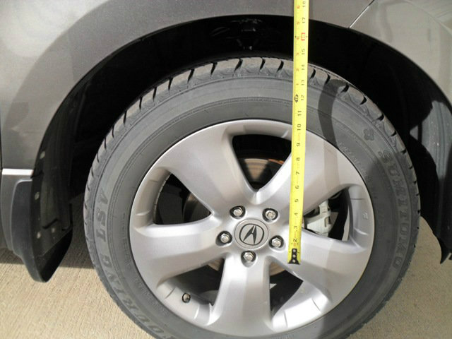
Before you do anything, measure the distance from the center of your wheel hub to the fender directly above with your vehicle setting on the ground normally. You will use this distance to compress the suspension before torquing the pinch bolts and damper flange bolts during the installation of the new strut assembly.
Removal
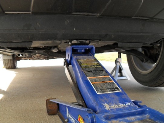
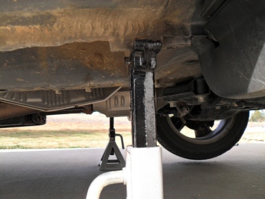
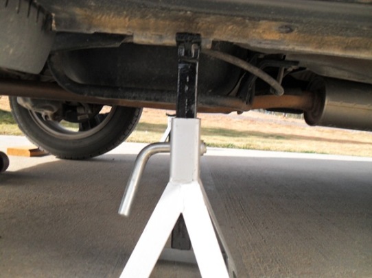
First, park the vehicle in a level area where you can work and put the car on jack stands supporting the car at the proper places on each side of the car making sure that wheels are off the ground, the car is level and that the stands won’t fall over while you are working on the front end. If you don’t know where the jack points are ask someone. You can damage your vehicle if you lift in the wrong place! Never put your body underneath the car while working just in case the car falls off of the jack stands. I placed some blocks of wood under the rear wheels to give slight support to the car and wedged some wood in front and behind tires to help keep the car from moving while I was working on it. You are going to be yanking and pulling on the vehicle while applying the tools for removal and installation. I also used a hydraulic floor jack to hold the front end up at the lift point in case the car fell off the front jack stands to prevent injury. This may be overkill but I figure it gave me more peace of mind while working.
Second, remove the front wheels using your impact wrench with a 19mm socket.
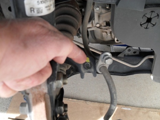
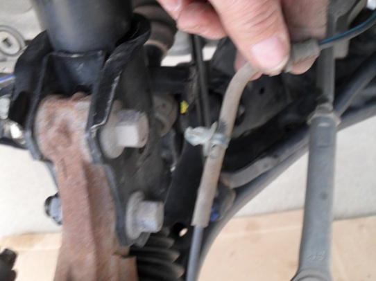
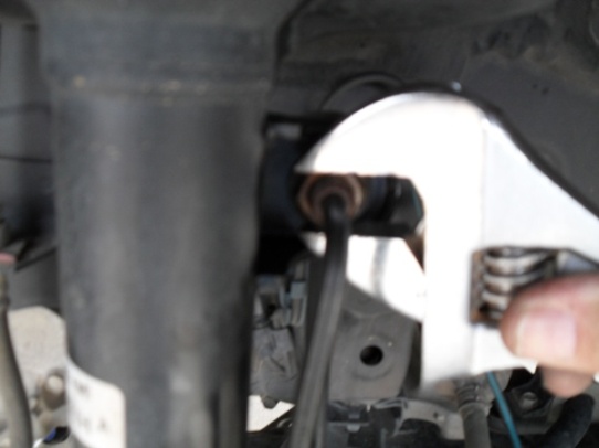
Third, remove wheel sensor harness clip, wire guide and brake hose bracket with 12mm socket from the strut assembly. Be careful not to damage the sensor harness! I used two screw drivers and needle nosed pliers to carefully remove the sensor harness clip from the strut body. This harness senses wheel speed for anti-skid and tire pressure so it is important. Place the sensor harness and brake line to the side away from your working tools and clear of the strut body. I used a u-shaped hacksaw with thin blade and fine teeth to carefully cut the old nylon harness clip from the sensor line while using needle nosed pliers to hold the nylon clip securely. Be careful!
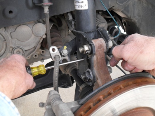
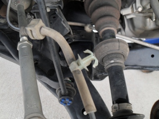
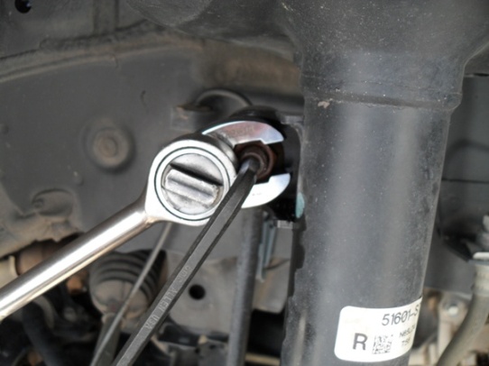
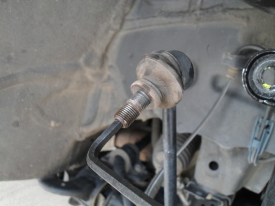
Fourth, disconnect the stabilizer link nut using a 17mm crescent wrench or crow foot and 5mm Allen wrench after soaking the bolt threads with Super Penetrating oil. I could not get the crowfoot to work here as the bracket on the strut was too confining to allow proper rotation of the crowfoot. The nut was pretty rusty and I ended up using an impact wrench to loosen the nut just enough to allow me to use a crescent wrench and Allen wrench to slowly remove the nut. I recommend a 5mm Allen on a 3/8 drive with ratchet wrench to remove the nut held with a crescent wrench. If you use those two tools, make sure you are turning the Allen wrenchwhich is in the bolt in the correct direction to loosen it, i.e. the opposite way you would turn the nut to loosen! I was then able to remove the stabilizer link and place it to the side and out of the way for the rest of the job. I checked with my local shop mechanic and he said this is how they do it. It worked! You will notice that the stabilizer link bolt rotates and pivots in all directions. Be careful not to damage the bolt/link dust boot! I then lubed this bolts threads with anti-seize for the installation.
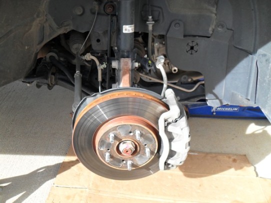
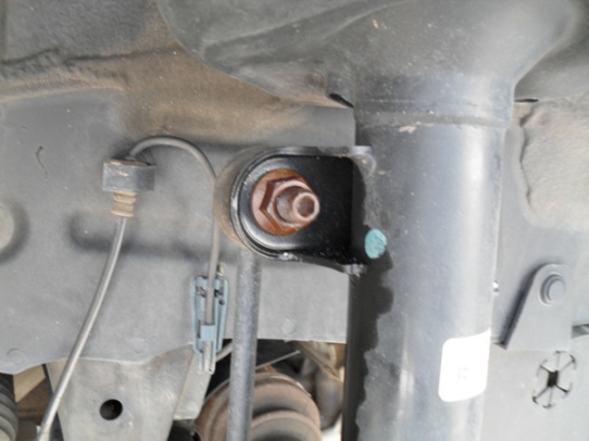
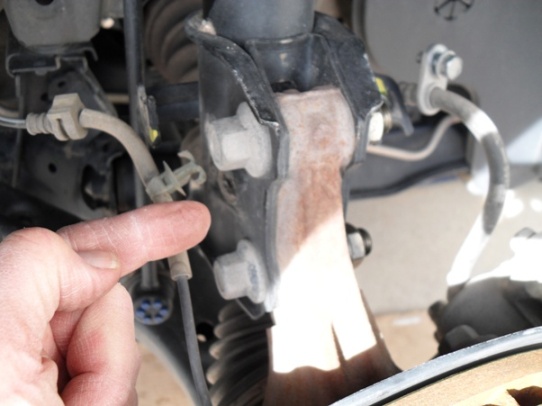
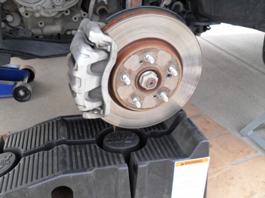
Fifth, I removed the damper pinch bolts and self-locking nuts using a 19mm impact socket/wrench on the bolt head and 22mm hex-head socket on the nut while supporting the knuckle with brake assembly on a ramp so that the heavy knuckle and brake assembly wouldn’t drop suddenly and damage the sensor and brakelines. . If the knuckle is still gripping the damper pinch bracket by friction/rust remove the knuckle and rotate it slightly rearward and downward to get it out of the way. Support the knuckle with a ramp or anything that will support its weight so that you can remove the strut later.
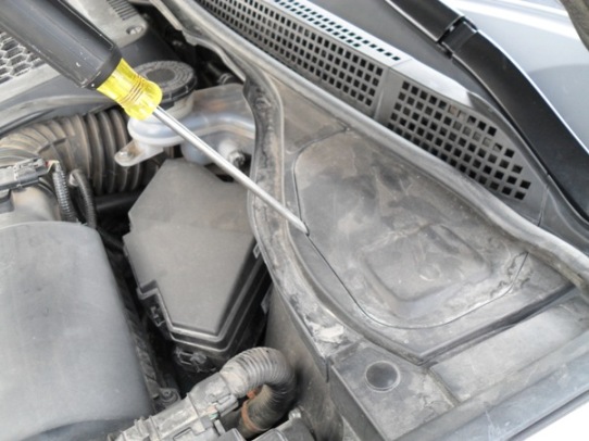
Sixth, open the hood to gain access to the cowl covers which set on either side next to the rear near the wipers. I used a small bladed screwdriver to pry them up in the pry slot of the cowl cover. Once they are cracked open, carefully lift the whole cover completely off and put it and the rubber weather stripping aside so that you can now work in that area.
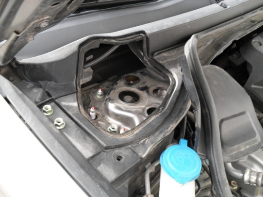
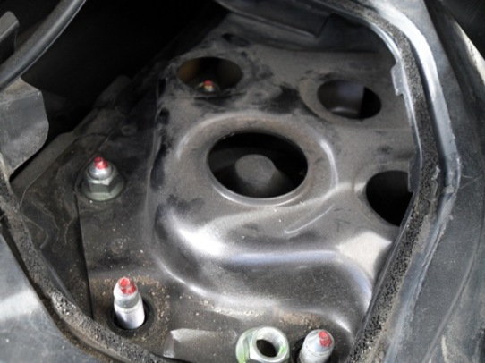
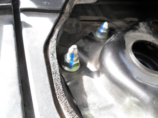
Seventh, I then removed the five flange nuts holding the damper/strut assembly with a 14mm deep socket. No extension needed if you use a deep socket plus the two longer bolts require a deep socket. You will notice three shorter bolts which will be the first ones to torque when installing the new strut assembly. I dropped a couple of the nuts in the shroud surrounding the flange bolts and had to use an extension magnet to retrieve them as my fingers wouldn’t fit into the holes. I left one nut still holding the strut weight until I positioned one hand under the fender supporting the strut assembly by holding onto the spring, then removing the last nut with the other hand.
Eighth, in the wheel well, I then grabbed the strut with both hands to lower it. I found that tilting the strut bottom toward the front of the vehicle allowed me to tilt the top of the strut toward me and carefully remove the strut being very careful not to damage the brake of sensor lines. Knuckle was rotated slightly rearward and downward.
Installation
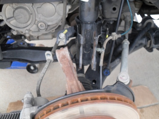
First, place the new strut /damper assembly in to the wheel well using both hands and being careful not to damage the brake or sensor lines. I was able to reverse the removal tilting to get the flange bolts on the top of the damper into their respective holes.
Second, loosely place the new damper flange nuts onto the damper bolts with one hand supporting the strut assembly and the other putting the nuts loosely on. I used some white lithium grease on the smooth portion of these bolts. Don’t them torque yet.
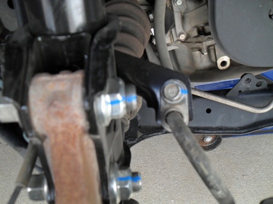
Third, loosely install the new damper pinch bolts and self-locking nuts with 19mm and 22mm wrenches. A crescent and ratchet with socket works fine here. This is a good time to check that you have the correct strut for each side by checking that the brake line bracket on the damper body is toward the front of the vehicle. J
Fourth, I connected the stabilizer link to the damper bracket being careful not to damage the bolt threads. I applied some anti-seize grease to the bolt threads and tightened the new self-locking 17mm nut using a 5mm Allen wrench to hold the bolt while tightening the nut. I don’t think it matters if you turn the nut or bolt until the nut starts to make contact with the damper bracket. Once the nut starts to get snug, and then hold bolt steady with the Allen wrench while tightening the nut. The recommended torque is 58 ft. lb. I could never figure out how to torque the nut with the tools I had available. I just tightened it down good and snug! I’m sure there is one for this job but I am not aware of it. I asked my local mechanic and he said that they also just tighten it ‘good and snug’. I also put a blue permanent mark on the nut and threads to indicate to me later if there was any loosening of the nut thus requiring more tightening! I will check all nuts and bolts after a few hundred miles or sooner to check for loose nuts.
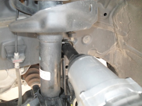
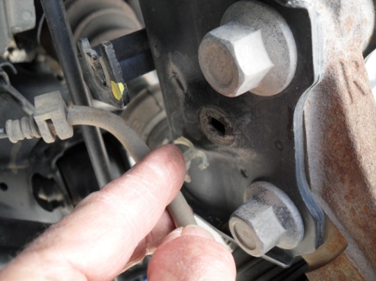
Fifth, I installed the new wheel sensor harness clip in the proper orientation, the sensor wire guide (rubber piece that is re-used to hold line in damper bracket) and the brake hose bracket to the damper using a 12mm wrench.
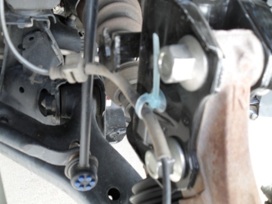
Anybody know what those little blue thingys are on the link?
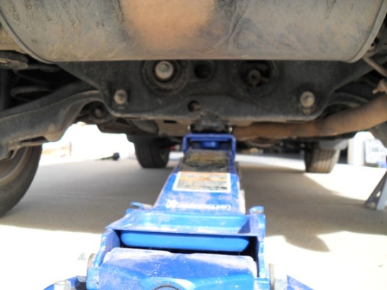
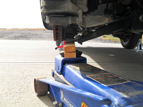
Sixth, raise the front suspension with a floor jack to load the suspension with the vehicle’s weight. I did this by using some small wood blocks between the floor jackand the lower arm assembly under the ball joint where it attaches to the knuckle and there are two bolts protruding downward from the arm. I avoided putting any weight on the two protruding bolts and carefully jacked up the suspension to support the weight of the car on the suspension. I noted that the distance from the center of the wheel hub to the top of the fender edge at the wheel well as 17 ½ inches while the car was setting in the driveway prior to jacking the car up on the stands. I also noted that the same distance with the wheels off the ground and on the stands was 21 inches. This meant that I needed to lift the suspension up 3 ½ inches with the floor jack to get the proper weight load on the suspension for the remaining bolt tightening. I figured this was close enough for me.
Seventh, tighten the new pinch bolts and self-locking nuts with the floor jackcompressing the spring in the suspension using a 22mm socket on your torque wrench and 19mm crescent wrench on the bolt head. I didn’t use any anti-seize on these threads as the old bolts came of easily and appeared in good condition. The recommended torque is 122 ft. lb. on the pinch bolts. Mark the bolt threads and nuts with permanent marker to ensure that you can check that the nuts don’t loosen later.
Eighth, now go back under the hood to tighten the damper flange nuts. Start with the three shorter bolts saving the two longer bolts for last. Using a 14mm deep socket and torque wrench I tightened the nuts to 33 ft. lb. tightening the three shorter bolts and lastly the two longer bolts. This step makes sure that you stagger your nut torque correctly. Mark the bolt threads and nuts with a permanent ink marker.
Ninth, install the cowl lid covers over the nuts that you just tightened in the last step. Re-secure the rubber weather stripping over the cowl lid.
Tenth, clean the disc brake surfaces in case you got some grease or oil on them. Re-install the front wheels and torque to 80 ft. lb.
Eleventh, check front end wheel alignment at your local shop as it has surely changed and will cause excessive tire wear if you don’t re-align your wheels.
Done! Enjoy your new smoother ride!
11-30-2012
The following links to parts diagrams might be useful when ordering parts for the strut assembly replacement:
PDF with dealer instructions for R&R of front strut assembly! My description follows this instruction set in attached file. Note that on p.4 they refer to nuts A&B in step 8 when I think they meant B&C in the diagram on p.3 step 2 of Installation!
Knuckle diagram(sensor wire harness) http://www.oemacuraparts.com/parts-c...hassis/knuckle
Engine Hood (Cowl lid) http://www.oemacuraparts.com/parts-catalog/acura/rdx/2008/5dr-tech/ka5at/body-air-conditioning/engine-hood 

Nice detail!
Posted by Diggymart on 10/18/19 @ 4:08:32 PM