You must be logged in to rate content!
7 minute(s) of a 114 minute read
8-7-2008
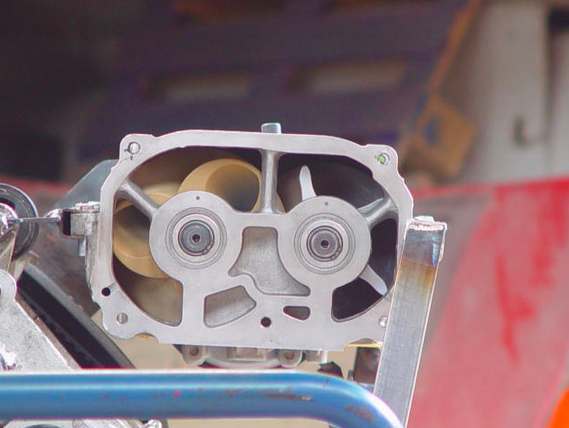
Just posting my thoughts on the AMG unit. It has a nice electrical operated drive clutch. Mercedes uses thes units without a bypass valve. The clutch is engaged by the engine management depending on engine load (MAP) and RPM. If the clutch is engaged and engine load is low for 10 seconds or so the clutch disengages. Interesting I read somewhere the clutch won't engage at RPM above 3000 because the load on the belt would be too high. I wondered how that would be in practice, cruising on the Autobah in your ubercar you wan't power but you first have to bring the revs down to below 3000?
Anyway, there is no bypass and the author of a test for these cars speculated the engine draws it's air through the screws of the AMG, with some drag. But I think, the clutch while disengaged has still some drag. If I spin the pulley by hand, the screws will spin a little too. I think while driving (cruising), the drag in the clutch and the vacuum on engine side will be enough to freewheel the screws to provide just the right amount of air, without putting load on the drive belt (fuel economy). Then when you demand power the clutch will be engaged. I would want to use this setup too then, without bypass valve. I have removed the airco from my car long ago but I will want to use the airco fan switch for the AMG: always off, automatic, or always on. The automatic will be depending on MAP, have to see if the MSII can do that without having to write extra code (that I could do but that means more studying for me).
Any thoughts?
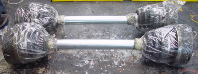
You don't know me well but you will learn hehe, I don't have any fancy machinery so I just started cutting the grooves with a handsaw with steel cutting blade. Though the teeth were getting less sharp soon so I just used a thin disc in the angled grinder :-) It's not very critical, I gave the CV 1 mm playroom or so and the retainers springs hold well, there is not really any force to them. I only cut through the splines so the base circle remains intact, I'm not to worried about strength loss. In the description of the axles it is said they are designed to spool up under load to reduce stress, well here is the page I bought them from: http://www.dansperformanceparts.com/...susp%20IRS.htm
Gee, magnafluxing? I'll just draw a straight line on them and see afterwards if the line is still straight...
My axles are ready but it will be a while...
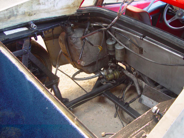
Yes, the engine bay looks very inviting to a longitudinal engine, exactly my thoughts. But we have some rules over here and a SC I can unbold and even I can return the regular suspension arms (though it would look funny), it is not allowed to change the wheelbase. I discussed everything with the guy that does the yearly check on my car, he always says, everything that is not forbidden is allowed. The law has become less strict, you were not allowed to weld on "wheel guiding elements" even not replacing a rusted spring retainer on a solid rear axle but now that is allowed. "Even making your own suspension arms?" I asked, Sure he said. Wheelbase is never measured only if they suspect serious accident damage to the frame.
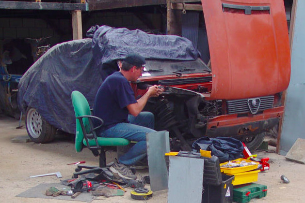
Wanted to make a baseplate for the inlet on the SC, but got the bolt holes wrong. So I took a picture from distance at full tele in order to print it at real size to make a template. I ordered two used 65mm Ford Explorer 5.0 throttle bodies (idea from "wildegroot") but I better wait until they arrived so I can see how I build the inlet, either steel base plate with formed steel inlet channels to the TBs or a thick (40 mm/1.5inch) alu spacer that I will cut the channels in. At my job we have this nice green plastic stuff that is easily machined and temp resistant, they make all kinds of things from it, I could use that too maybe.
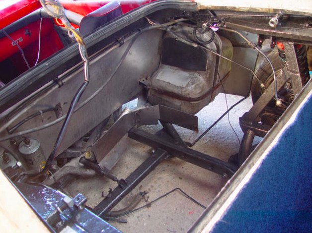
My brother (the one that doesn't hate cars) was there today working on his Alfasud, so I could borrow his air impact wrench that he normally locks up to remove the remaining 2 engine mounts from the chassis, they spin just around in their housing if using a normal wrench. Also cleaned the engine bay with some black paint here and there, welded the trunk floor and put in dampening mats and some left over carpet, now I can throw tools and parts in there without worry. Eventually there will be black wilton whool of highest quality in there of course. Or something nice the carpet store around the corner has.
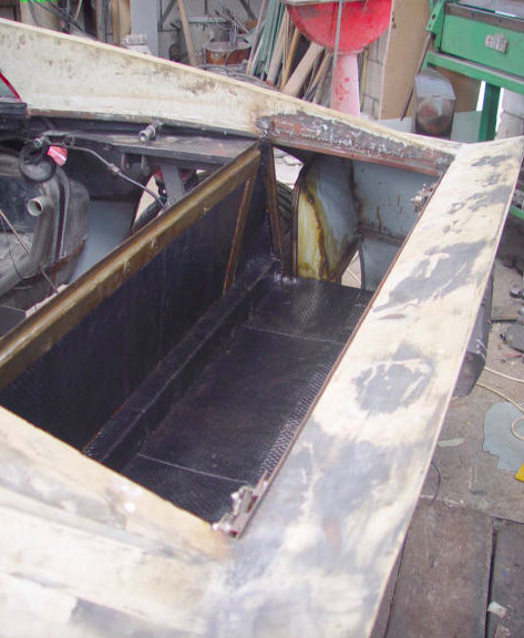
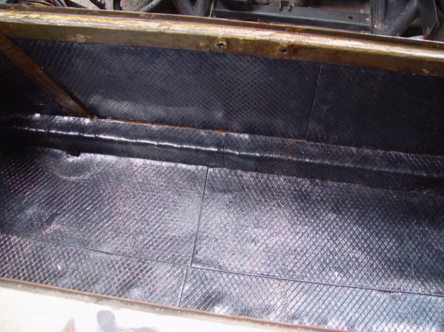
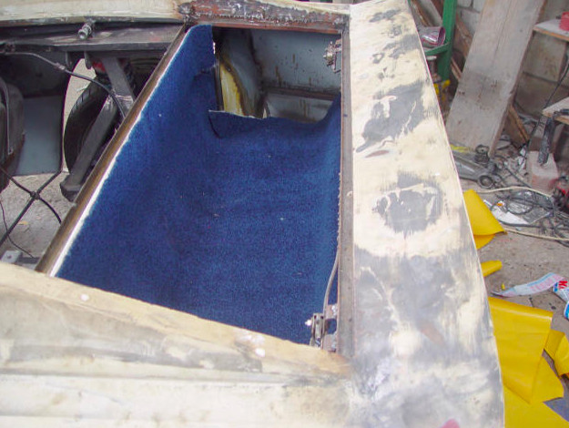
The side pockets in the trunk were the 3 side vents will be, will have an open bottom and the side vents will be "real" in the way that the openings are not closed as in the previous setup. However they will do nothing really, not even removing hot air from the rear tires because the innner wheel wells will still shield the tires. Water that enters through the side vents just drop on the street, also the rear lid vents are closed in the rear 1/3 part, don't want water in my trunk, and they drain on the drain channels and to then to the right and left side openings. There will be removable panels left and right, alu 1.5 mm with carpet glued to it, that clamp on top under the seal rubber lip. The left one will have a pocket in it for the MegaSquirt. I can remove the panels for acces and cleaning of the side pockets, dividing line is between the rear lights.
And I realized today, I will need to make an engine stand. Also realized, to remove the pistons, I need to seperate the gearbox from the engine. Obvious you might think, but I just realized today how much work that will be. The way the engine is sitting now, resting on it motor mounts, could I just unbolt the lower part and lift the engine from the gearbox section, or are there hidden things in there like oilpump? What I mean is, could it be seperated without removing the engine and/or gearbox sump cover first? Of course the bellhousing will have to removed. I better start making a clean corner in the shed I'm working for all the parts.