You must be logged in to rate content!
9 minute read
308 Instrument panel lighting upgrade tests
Compliments of chairpilot @ ferrarichat.com
9-16-2009
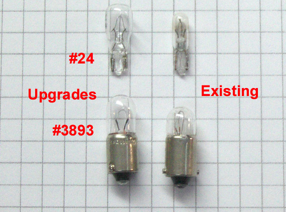
While my dash is apart and I’m getting the vinyl repaired at a local shop, I decided to investigate the #3893 and #2723 lamp upgrade recommendations in past posts. Increased heat & current were my main concerns, as the potentially higher wattages would generate. I purchased the lamps at a local Kragan Auto. They did not have the #2723 but did have a #24 which appeared to have the exact same size base and prongs but a slightly larger glass bulb diameter as you will notice from the attched pictures.
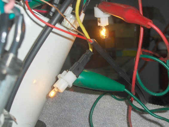
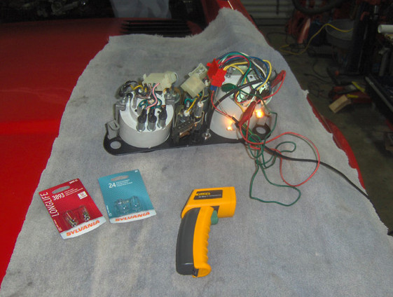
The setup - 7:00 PM Wed. - today
Tack lamps (bayonet) - original IEUCI 2C 12v 3w – upgrade Sylvania # 3893 13.5v 4w
Speedo lamps (mini) - original UCI 1.2w – upgrade Sylvania #24 14v 3.4w
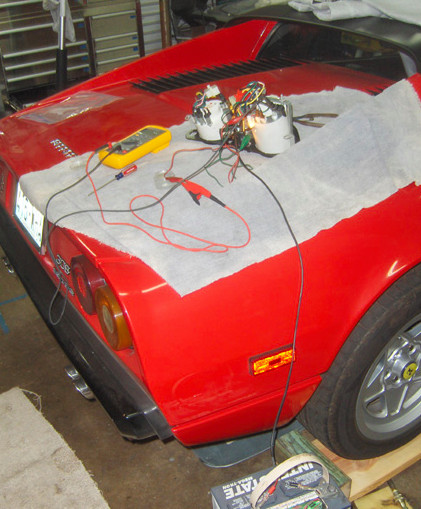
All “bench” connections made to my spare 24F battery.
Ambiant garage temp was 75-76 F.
The right and left turn indicator lamps appear the exact same as the speedo lamps. Right now these (UCI) lamps are 98% non-visible in the daytime. Assuming these tests are favorable, I may use the upgrade lamps in those positions as well to improve their brightness.
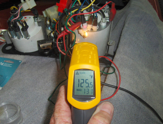
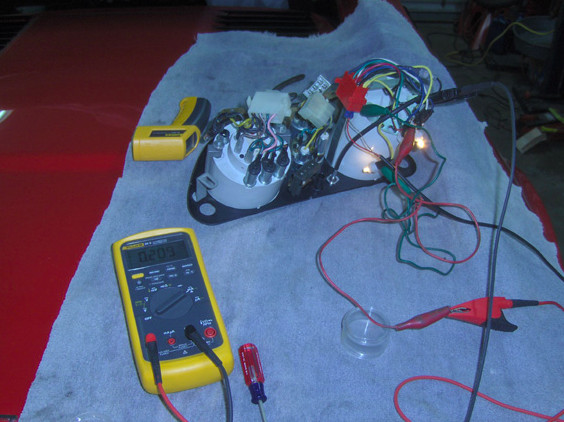
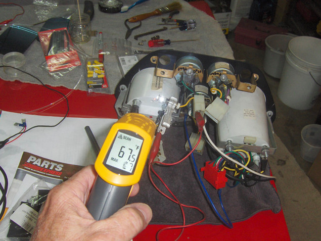
Initially I did not notice any major difference in illumination intensity between the original mini and the #24 but did between the larger bayonet lamps. My test consisted of putting one of each lamp in the compatable OEM socket and taking pinpoint temp readings at the start and about 30 min later, all out of the gauge housings. My Fluke 62 Mini infrared temp meter takes both intantainious and saves max readings while holding down the trigger. So I was able to scan up and down the lamp, socket and feed wire to see the lowest and hottest spot temp locations as well as an overall maximum – at each reading.
UCI 1.2w – 77F 30 sec after startup, 91F max after 30 min; current draw - 82 mA
#24 – 89F 30 sec after startup, 119F max after 30 min (130F at about 20 min - ?); draw - 209mA
IEUCI 2C 12v3w - 88F 30 sec after startup, 101F max after 30 min; current draw - 222 mA
#3893 - 135F 30 sec after startup, 170F max after 30 min; current draw - 291 mA
Results:
#24 generated a 30.7% temp increase and a 154.87% current increase
#3893 generated a 68.3% temp increase and a 31.08% current increase
This is not a very scientific effort. Just a seat of the pants set of readings. My concern now is if the heat increase will negatively affect the plastic housings. I’d like to know if any of you out there have done similar tests or have made these lamp changes and experienced any problems from higher temps or current draws.
1.5 hour update on the #3893 test (8:21 PM)
IEUCI 2C 12v3w - still at 101F
#3893 - up at 190F now
I took depth readings of all the lamp sockets for the locations listed below to determine any clearance issues. It is easier to follow if you download my WORD file as the post does not clearly line up my data.
OEM’s are of course no problem. I have no LED’s in hand yet so they are to be determined. But maybe MAGNUM can fill in the blanks there. The 3893 appears 1mm too long for the clock. But of course you can just back off some on sliding in the socket-lamp assembly.
Bayonets -
Location# of Lamps Clear dpth OEM Lamp+sckt w/3893 w/B9 HP6 LED
Tach235mm29mm32mmTBD
Fuel132mm27.5mm30.5mm TBD
Oil Press132mm27.5mm30.5mm TBD
Water Temp 132mm27.5mm30.5mm TBD
Oil Temp132mm27.5mm30.5mm TBD
Clock1 29.5mm27.5mm30.5mm TBD
Mini's -
Location# of Lamps Clr DpthOEM Lp + sktw/2723w/24w/LED
Speedo221.5mm18mm18mm21.5mm TBD
Turn Lf129mm18mm18mm21.5mmTBD
Turn Rt129mm18mm18mm21.5mmTBD
Hi Beam129mm18mm18mm21.5mmTBD
9-24-2009
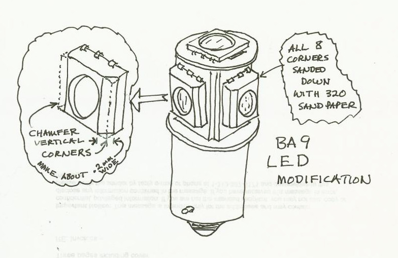
I received the larger LED's and proceeded to install them. To my "horror" they did not slip right in as expected. The specs on line indicated they were of a diameter small enough to fit into the lamp sleeves of the gauges. Upon closer inspection I could see that the problem was due to the corners of the individual LED chips protruding past the diameter of the lamp base. The fix was easy. I took some #320 wet-dry sandpaper cut into a narrow strip. Backed up with a tiny flat file, I lightly knocked the edges off to about a .2mm (estimated) width - a very small amount. That did the trick and the LEDs slipped right in. The attached drawing shows the situation better. Also note that some of the LEDs will bottom out before the socket returns to its original depth so just back it off enough not to jam the LED against anything.
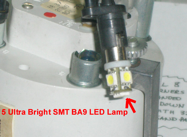
These LED's are bright when I bench tested them!!! I expect they will surely do the trick. I'm still waiting for the 5 mini LED's that go into the Speedo, Parking and turn indicator lights and will report any issues there once installed. Tonight I will check out the effects in the dark and compare them to Magnum's results in his previous post.
BTW - I elected not to upgrade the Hi Beam, Rear Fog and Spare indicators in part because they are illuminated Ok and because these LED BA9's are about $9 each plus shipping.
This project was not difficult. PM me anytime if you have any questions on this conversion.
I'm also attaching an updated depth chart of all the instrument sockets.
Well, I took some temp readings with the new LED lamps using my infrared gun and it's as we would expect - cooler. Laughable really. These LED lamps are an awesome upgrade.
Garage ambient (taken at the ceiling drywall) - 65.5 F
Fuel Gauge (housing) - 65.5 F
Fuel Gauge Lamp socket (sleeve) with the 5 LED (BA9 type lamp) take at 30 sec after turning on - 65.5 F
Lamp socket after 3 min - 68.5 F
Lamp socket after 20 min - 70.0 F
I also took a direct temp reading on one of the LED lenses (out of the socket) - 79.5 F
These lower lamp temps may help the AC work better at night (LOL!).
If you drive at night - DO THIS UPGRADE!!!
10-9-2009
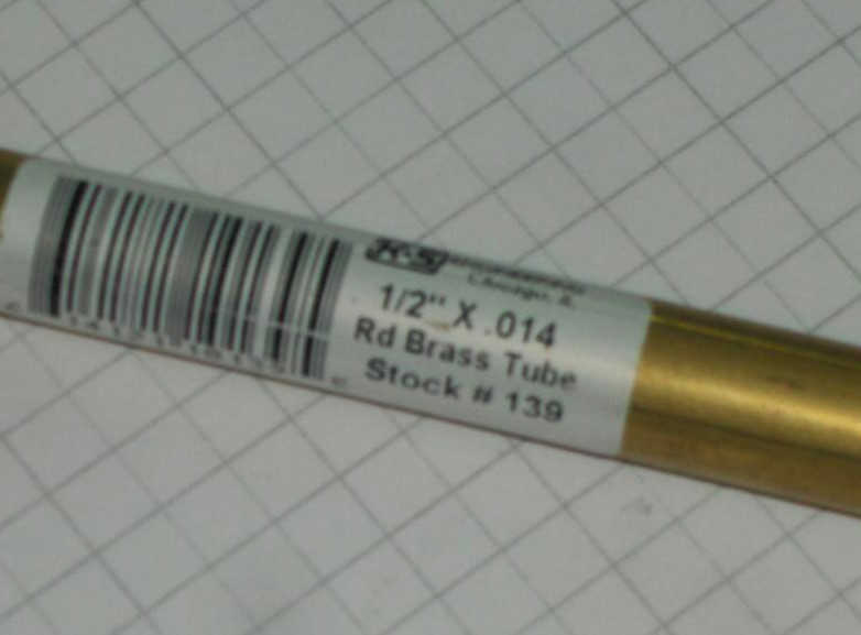
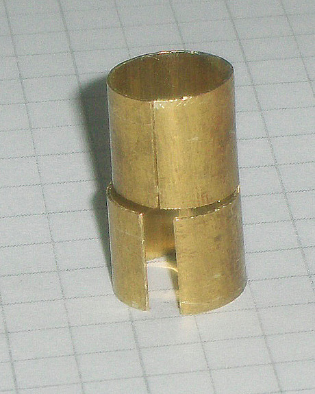
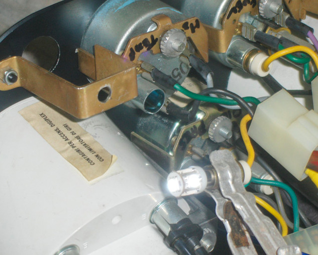
Yes, the side mounted LED's are best for the background illumination. The 5 LED lamp is a bit too long (as we see from my previous posted depth chart). But I made a quick and simple sleeve-socket extension out of some 1/2" brass tubing I got from the local hobby shop (I keep an assortment of brass and stainless tubing around the shop for just these kinds of things). First, cut one LENGTHWISE slit off one end of a length of the tubing for about 1". Then at about 1/2" from the end, CROSSCUT another slit just past half way through the diameter. Make a third cut off at the 1" mark to detach your "new" sleeve extension from the length of tubing. Adjust the spread on each half "C" to fit snug to the socket and sleeve diameters to insure a good grip and ground connection. Snap ring pliers work great for this part. It took me 3 minutes to make. The brass seems to have enough "spring" in it to stay firm - and it won't rust.
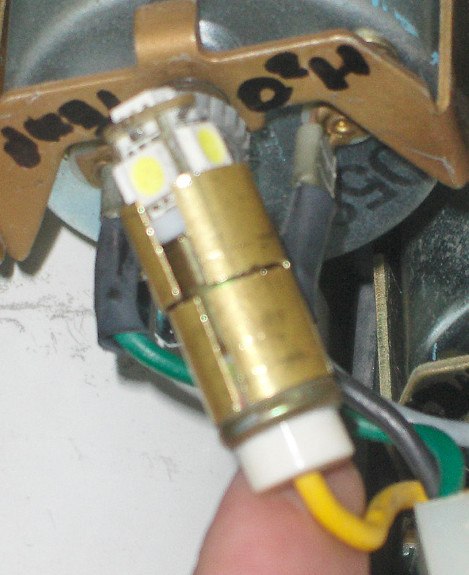
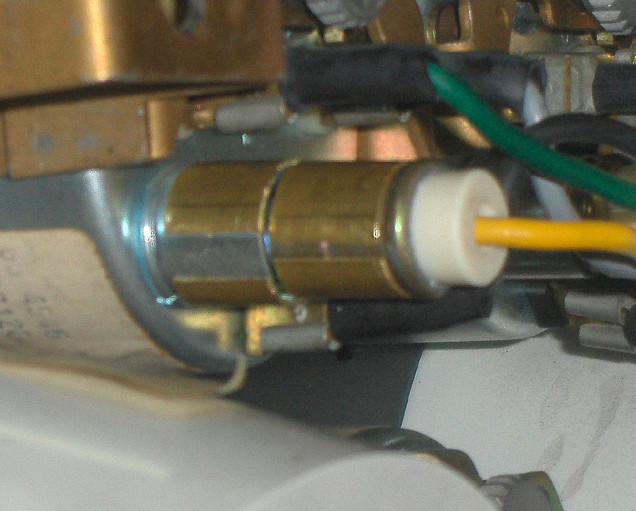
If I knew how to remove (electrically) the end LED from my 5 LED lamp assembly and still have it work I may modify the clock lamp later and remove my extension since taking out the clock is the easiest of all the gauges. My pictures show the sleeve extension mounted to the Fuel guage the example.
BTW - the tubing cost $2 for the 12" piece