You must be logged in to rate content!
4 minute read
Hella #85115 Supertones horn installation in an S2000
Courtesy of Bob A (SD) @ www.s2ki.com
Given that the FAQs the old timers posted are no longer accessible, I figured I'd share some information on installing these 118dB electric horns as replacements for the factory dual 110dB horns. Hope this is of some help for those looking at doing this modification. And yeah, they ARE satisfyingly LOUD -
The Hella instructions have 4 different diagrams. 2b is the diagram to use on the S2K for swapping out the factory horns for the Hellas.
Other threads have the following information but I'm including it here for consolidation:
--use heavy gauge wire (14 is what I choose)
--use the supplied relay
--use a separate fuse and wiring
--the copper colored spade connector on the horns is +; the silver is -
--do not simply swap these horns out for the factory as the factory wiring and the fuse (with other components in the circuit) is not up to handling the two Hellas
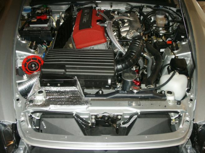
This first picture shows the basic wiring. The battery's positive terminal is tapped with an inline fuse holder and feeds the Hella relay (connection 30). The relay is grounded (relay connection 85). I used a crimp splice block to tap into the factory horn trigger which was the factory wire going to the AP1 plug and original horn. This is routed to relay connection 86. The horns are fed in parallel from relay connection 87. I used a crimp splice to take the single wire from the relay and convert it to two... one for each horn. Note that the relay is mounted on the 10mm threaded hole already available next to the shock tower. Also note that I mounted the Hella horn to the back of the car's horn mounting bracket unlike the factory horn which was mounted to the front.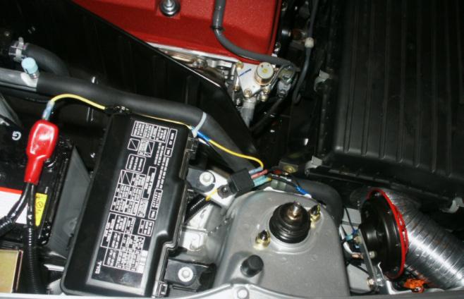
Here's a closeup of the crimp splice block I used to tap into the factory horn activation wire. I peeled back a bit of the electrical tape between the spiral cable protector and the female AP1 plug that was connected to the factory horn mounted in the enginebay. That allowed the crimp splice block to be used. It allows wires to be laid side by side and when closed cuts the wire insulation with a conductive bridge. It is the blue block in the center of this picture. To ground each horn and the relay I simply used the individual mounting bolts to anchor the ground wires. Checked it with a VTVM and found this configuration was good to go so I ran with it instead of running longer wires to the main chassis ground located in the engine bay just behind the passenger headlight assembly.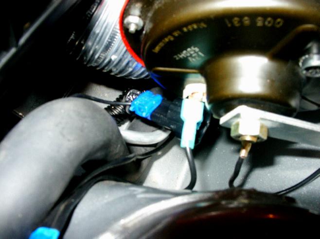
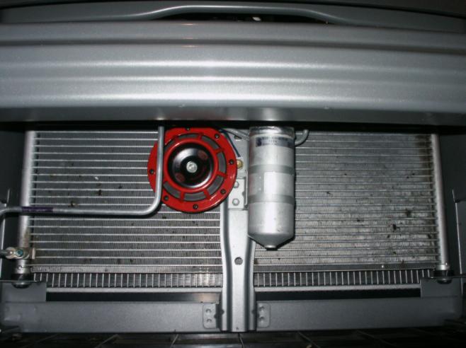
Here are pictures of the completed installation (which also shows the modified airbox, mini-radmat, and Greddy PCV valve oil catch tank I previously installed). The bumper (with Coastal Metals grill) and Coastal Metals engine bay accessory (air director) have not been re-installed in these pictures. I placed the 500Hz horn in the engine bay and the 375Hz horn in front of the radiator.