You must be logged in to rate content!
15 minute read
OEM Audio Amp Repair - fix buzzing/noise/no volume!
Compliments of chefboyardee @ https://acurazine.com
12-8-2014
Looking through the forum, I've seen several threads on audio amp issues, and there seems to be a pretty common issue with our amps. Either there's a noise at low volumes (alternator/spark noise) or the volume is much reduced, or both. I had the same problem (both) recently, and decided to figure out why the amp failed. Turns out, all that was wrong was that the small 5mm capacitors in the amp were going bad. Bad caps are a fairly common thing in older electronics, and fortunately they're pretty easy (and cheap!) to replace.
If you know how to use a soldering iron, you should be able to fix this yourself. The partsshould cost less than $20. Even if you're not that good at soldering, there are lots of YouTube videos that will give you everything you need to know, and this will be good practice.
Even though it's easy, it's a little tedious, so give yourself 3 hours to do it. It'll be worth it.
Here's what you will need:
- Safety Glasses
- Soldering Iron
- Solder (use the thin electronics kind- the plumbing stuff is way too thick for this)
- Screwdriver (Philips #2)
- Needle Nose Pliers
- Solder Sucker (You can get this at Radio Shack, see YouTube for how to use it)
- 9x 10uF 50V electrolytic capacitors
- 18x 1uF 50V electrolytic capacitors
I had bought my capacitors here: Futurlec.com as part of a different project, but you can get them wherever. I didn't use exact replacements, some of the OEM caps were 3.3uF, 4.7uF, etc, and I just replaced all those with 10uF. I just used what I had and it worked out fine. If you want to be Type-A and use the exact values, be my guest, but using only 1uF and 10uF didn't alter the sound as far as I could tell. Just make sure they're 50V or higher rated.
- Start by removing the amplifier from behind the passenger kick panel. There is a plastic cover, the kick panel, right next to the passenger's feet. Remove that. It may also help to remove the black panel above it to give yourself some room. Just pull on them and they'll pop loose- there are no screws holding them down.
Remove the connectors from the bottom of the amp, black and grey. Then remove the two bolts holding the bottom of the amp to the car's frame. There is one more bolt (a nut, actually) at the top of the amp. It's tricky to get to, but you only need to loosen it. There's another wire harness in your way that you can release by pulling straight down on it. I was able to get to the nut using a ratchet, 3" extension, and a universal joint. DO NOT completely remove that nut- once it's loose you just slide the amp off the stud. You don't want to have to get that nut back on there, trust me. - Open up the amp by removing the four screws on the long edge of the amp, and then the four screws from the top bracket (the side without connectors). The circuit board should slide out of the case still connected to the top bracket.
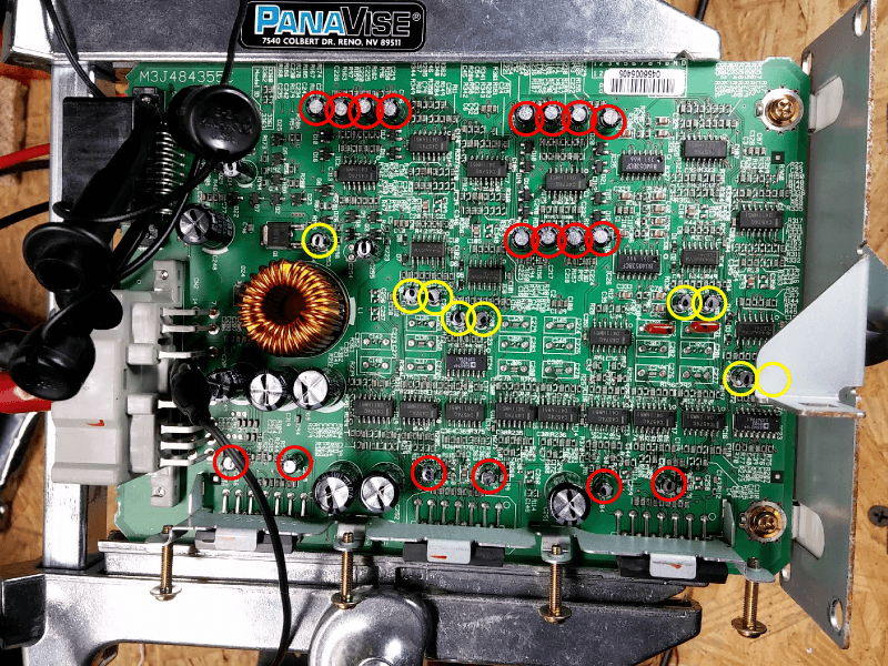
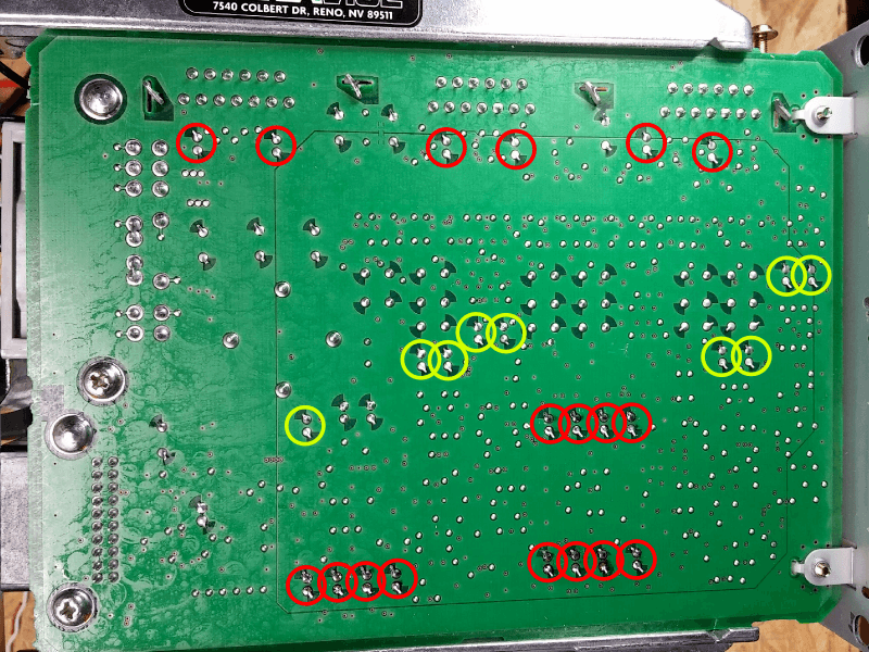
- Locate the capacitors you will be replacing. The pictures show all the 1uF caps circled in red, and the rest that I replaced with 10uF in yellow.
- Before trying to yank out the old caps, straighten out their leads. Safety glasses are really important here! Heat up and melt the solder joint around each lead and use a tiny screwdriver or your pliers to straighten out the lead a little. It doesn't need to be perfect, just close. Please don't use the soldering iron tip to pry at the leads- this is a guaranteed way to get a face full of molten solder.
- With your pliers, grab the body of one of the caps. They're weak and squishy, so don't squeeze too hard. On the opposite side of the board, Use your soldering iron to heat both leads of the cap simultaneously. Pull gently on the cap to free it from the board. Don't pull hard. If it's not coming out, the solder is not melted yet. If you pull really hard you will pull the plating out of the hole, which would be very bad. You should actually add more solder to help spread the heat- it makes it much easier. You will probably end up squashing and maiming a few of the little buggers, but that's okay. It's their fault you're doing this in the first place and they deserve it.
- Use your soldering iron to heat each hole from the top of the board, and use your solder sucker to clean out the hole from the bottom. When you're done, each hole should be clear of solder and ready for a new capacitor. If you encounter a hole that you can't clear out, try poking a regular straight pin through the hole while heating it with the iron.
- Insert the correct replacement capacitor to each location. Refer to the picture above if you've forgotten which goes where. After threading the leads through the holes, you can bend the leads in opposite directions flush to the circuit board to hold it down.
- Now solder those things down! Make sure to completely heat each joint and use enough solder to prevent a cold joint, but not so much that you're globbing it everywhere. Look at the other solder joints on the board as a reference. When you're done, clip the leads close to the joint to make it look all professional-like.
- Reassemble your amplifier and reinstall it in your gorgeous TL. Remember to reconnect the wire harnesses and tighten that annoying nut on the top bracket.
- Go for a drive and enjoy your newly-restored audio with no weird noises or buzzing. Party like it's 2004. Or '05. Or whatever year your TL is.
I should add that you can get the capacitors you need on Digikey (in the US) as well, and the shipping would probably be cheaper and faster than Futurlec. Plus you can get nice, Nichicon top-shelf audio caps and they're still like $5 total.
18x Digikey 1uF 50V Audio Capacitor
9x Digikey 10uF 50V Audio Capacitor
If you want to pick exact values, you can find them all here: Digikey Nichicon FW Series Capacitors
If you order from Digikey, pay attention to the price breakdowns. It's actually cheaper, at the time of this posting, to buy 25 1uF caps than it is to buy 18 of them.
That's a good question- and the answer is no, they looked completely normal. I think since they're so small, they don't have as much tendency to puff up when they go bad. There was a slight reddish discoloration at the base of each one, but I'm not sure if that was related or not. Several of the caps that were working just fine also had similar discoloration.
I tested them after I pulled them out with an Agilent DMM, and most showed a capacitance of below 2nF. A few had maybe 50% of their original rated capacitance.
Sorry about the pics. I didn't think to start taking pictures until I had replaced a few of them already. If you notice, the caps without black marker on the top are the ones I had already replaced.
12-16-2014
I wish I would have written down exact values for everything, but I did take a lot of pictures, so I've done my best to piece together the values of all of the other caps. Here is what I've got:
1x 4.7uF 50V
1x 47uF 25V
1x 100uF 50V
4x 470uF 16V
2x 1000uF 16V
If anyone does this fix and can verify this list (even better, a comprehensive list of all electrolytic caps on the board) that would be awesome. If I end up pulling my amp out again I'll post it. I'm 99% sure this is right, though.
I didn't replace these simply because they're not directly part of the signal chain, and they seemed to be working fine. Also I already had the 1uF and 10uF caps, but not replacements for the bigger ones. If they go bad eventually I'll just have to crack it open again and do it then. If you're going to do this and are buying caps anyways, I say go for it. It certainly can't hurt, and the Nichicons are definitely an upgrade.
As for polarity: yes, it does matter. You can buy nonpolarized capacitors, but the original ones, the ones I used, and the ones I linked are all polarized. They will fail quickly (and sometimes spectacularly) if you get them backwards, so make sure you get it right!
If you care about the technical details: the reason they're polarized even though audio is an "AC" signal, the "zero" point is actually at about 2.5v in most stages of this amp. Because of this, the signal is always at a higher voltage than ground. That way they can use simpler single-supply op-amps instead of power supplies and op-amps to do both positive and negative amplification. This is slightly oversimplifying it, but I hope you get what I'm saying.
Sorry the links died- I swear they worked when I posted them.. I should have known better.
I actually found higher-quality caps (KZ/FG series) than the ones I had posted earlier (FW). I'll give the part numbers for those. Just know that really, the difference between these and the cheap ones you can get anywhere else is pretty small. Even with these super-nice ones, you're looking at a total cost of like $15 plus shipping.
Digikey part numbers:
1uF : 493-10944-1-ND
10uF : 493-13405-ND
47uF : 493-3194-ND
100uF : 493-3195-ND
470uF : 493-3192-ND
1000uF : 493-10989-1-ND
mzilvar: I actually spent a lot of time probing around the board with an old analog oscilloscope and a function generator pushing a 1kHz sine wave through the signal chain. I don't have a schematic, though that would have been nice! What clued me in to the failed caps was that I was seeing different signal drops across them between channels. On one channel I would see almost no drop across a certain cap, while another channel would show a 90% drop in p-p voltage. I wasn't surprised. Bad caps are probably the number one cause for failed electronics, especially boards from the early/mid 2000s (as polobunny mentioned). After I pulled a few and measured them with my DMM, I was positive that I had found the problem.
2-18-2015
Just to update everyone- I was curious to see if it made a huge difference to swap out all the caps with the Nichicon KT series that ebs007 listed. It's a good point about the 105C rating, though where I live now I doubt it'll ever get that hot.
I pulled my amp again and replaced the whole set. I can verify that ebs007's list of capacitor values is 100% correct (not that we ever doubted you- thank you again!!).
I decided to try boosting a few of the decoupling (non signal chain) capacitor values, plus I accidentally forgot to order the 47uF one, so here are the mods I made:
- Replaced all 470uF caps with 1000uF
- Replaced both 1000uF caps with 2200uF
- Replaced the 47uF cap with 100uF
All the voltages are the same as their original values, and all were still with the Nichicon KT series. These mods still fit the original holes (almost) perfectly, so none of the caps are sitting crooked or sideways. Also, the 2200uF caps still have a good 1/8" of clearance from the top of the case, so plenty of room.
Here's the final result:
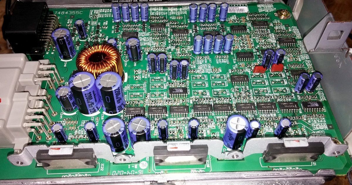
As far as sound quality goes: I'm not going to lie, I can't really hear much of a difference. I'm not a huge audiophile, but I do appreciate a good sounding stereo. I think it sounds great, but not significantly better than before. I spent a few hours trying to make high-quality recordings in the car before and after the swap and then compared the spectrograms.. and didn't notice any huge differences. Spectrograms are actually pretty lousy at revealing what our ears actually hear, though, so take that for what it's worth.
I will, however, rest easy knowing that I won't have to deal with this for the rest of the car'slife.
After all that, I'm going to stand by my original statement: it's probably best to do everything if you're going to go through the effort to pull your amp out and do this repair. If you want to do the bare minimum and just get it working, though, you can get away with just doing the small caps (the ones up to 10uF) and you'll probably be fine. Either way, you're not significantly improving the sound of the amp, just repairing it. I chose the Nichicons for dependability, not just sound quality.
3-2-2015
I think we have determined that the KA series caps are a little too large to fit into the case without having to tilt them. Also, they are only rated for 85C, not 105C like most automotive components.
Here, with Mouser Electronics part numbers, are the exact replacement values for every electrolytic cap on the board. These are the Nichicon KT series, which is still in their "High Quality Audio" series, just temperature rated for automotive applications. They also match the sizes of the original capacitors (except the smallest ones are a little taller- no big deal).
Value Part Number Qty. Price ea. Ext. Price
0.47uF 647-UKT1HR47MDD 6 $0.32 $1.92
1.0uF 647-UKT1H010MDD12$0.32 $3.84
2.2uF 647-UKT1H2R2MDD1$0.32 $0.32
3.3uF 647-UKT1H3R3MDD6$0.32 $1.92
4.7uF 647-UKT1H4R7MDD1$0.32 $0.32
10uF 647-UKT1H100MDD2$0.32 $0.64
47uF 647-UKT1E470MDD1$0.41 $0.41
100uF647-UKT1H101MPD1$0.57 $0.57
470uF647-UKT1C471MPD4$0.57 $2.28
1000uF647-UKT1C102MPD2$0.95 $1.90
Total: $14.12
Sorry for the poor formatting. I don't know why AZ won't support the TABLE tag in vB/BBcode...
As far as I know, with the fade/balance setting on the HU set to center, you should probably hear the fronts slightly more than the backs when sitting in the front seats. That's how mine is. All the speakers are roughly the same sensitivity, so for a given amplifier power they should all be equally loud. The fronts also have dedicated tweeters, so they can 'seem' louder and more present.
If the rears are still significantly quieter, then the easiest answer is to adjust the fade to send more to the rear. If that isn't enough, I would double-check polarity on all the caps you replaced first. Then check all the speaker wires and speakers. You can measure resistance with a multimeter from speaker+ to speaker- at the harness to the amp to check both the wire and speaker at once. I haven't done it, but I would expect a resistance of a few ohms (1-8 ohms?) and the two rears should match each other pretty closely. The fronts may be slightly different because they are also powering the tweeters, but they should still be in the same ballpark and should match each other.
2-1-2016
As for voltage ratings, the signal chain (the smaller ones) caps should all be 6V or higher (2.5 volt is the zero-point of the signal. The signal actually ranges from about 0-5V). The bypass caps should be 16V or higher. Really though, I would use the factory values as a minimum value. ebs007's post (#32) gives the stock voltage ratings.
Higher uF is better for the bigger bypass (100uF and up) caps, but you don't really need to go crazy here. I doubled the 470uF and 1000uF ones and didn't really notice any difference. Just be careful to look at the physical size first. The very first list of caps I made, I forgot to check the sizes and some were too big to fit without having them laying sideways.
The Nichicon KT series ones that I used were just about perfect. I would highly recommend those as they fit perfectly, are automotive temp rated to 105C, and are designed for premium audio applications. Check out post #55 for a shopping list with part numbers.