You must be logged in to rate content!
14 minute read
Passport 8500 X50 Smartcord Hardwire (A6)
Compliments of Boston Driver @ audiworld.com
Disclaimer: I will start with the usual warning about working with electrical stuff. You should disconnect the battery to avoid any risk of harming yourself or your car. If you are uncomfortable with wiring or worried about doing any of this, seek professional assistance with this installation.
I am basing much of an install on what I saw in the Tech Section for a hardwire install for an A4 (by Valentin Berechet). However, that location would be difficult for an A6, since there is no small dash insert to remove and drill. Any under the dash installation would require drilling into very expensive parts, so I turned my attention elsewhere on the dash. I also sprang for the Smartcord Hardwire Kit from Escort, got it for less than $30 from eBay. I did not want to take apart the cig lighter Smartcord, because I want to use that in my wife's truck for long trips.
Total time, including the photos, was around 3 hours. If you have never removed the dash panel or the A-Pillar trim, expect to take a bit more time.
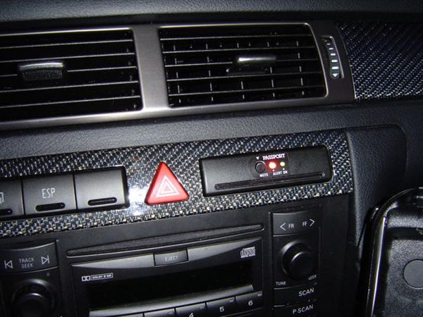
First, the teaser shot of the final result...
I originally thought that the install could possibly work in the dead button to the right of the ESP (the one to the left is for the rear window power sunshade). However, the button itself is too small for a simple install, and the wiring tunnel behind the dead button is too narrow for the circuit board.
I never use the in-dash cup holder, for fear of beverage or condensation finding a way into the radio or the climate control system. Rather than cutting that up, I found the coin tray in the AudiWorld Classifieds for this install (part # 4BO941561C) for $20.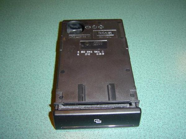
COIN TRAY DISASSEMBLY
The first step is to disassemble the coin tray. First, with the coin tray closed, remove the little yellow gear wheel by pressing down with a finger until it releases through the hole on the top of the tray housing.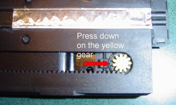
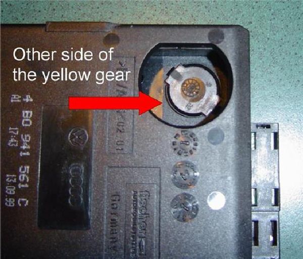
Then open the tray (watch out, with the gear removed, the tray snaps open pretty fast!). From the underside, pull the tray housing away from the bottom of the coin tray's retainer tab.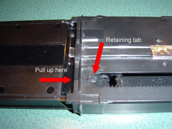
Remove the tray and set aside the spring and drum (I did not reinstall the spring, since there is no need for the tray to spring open when it is pressed).
SMARTCORD DISASSEMBLY
You are now ready to make some modifications to the tray to install the circuit board and wiring for the Smartcord. To do it right, take the Smartcord apart. There is one screw on the underside holding it together.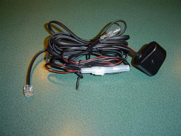
Then, pull the two halves apart, and set aside the sticker for later use. TIP: if you have some glossy surface to mount this on (like the stuff that comes with stickers and labels), place the sticker there so you do not loose any of the adhesive.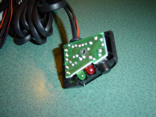
Remove the circuit board and wiring from the bottom half and set aside.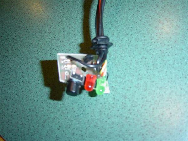
FACEPLATE MODIFICATION
Draw a template of the holes in the sticker using masking tape. Place the template on the faceplate of the coin tray, so the bottom edge of the Smartcord sticker lines up with the top edge of the strip along the bottom of the faceplate.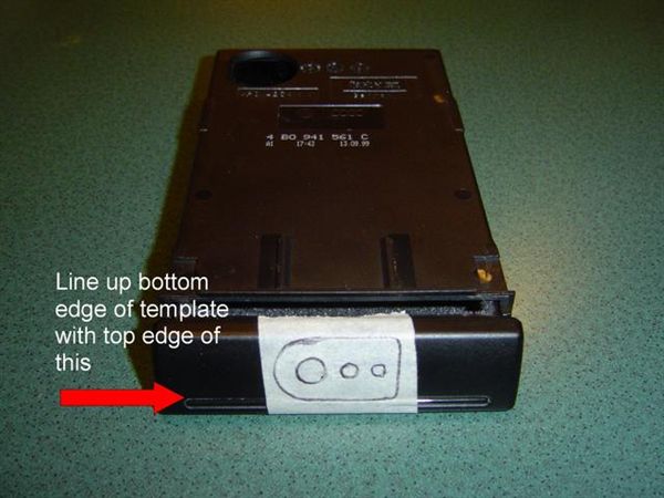
Next, remove the faceplate, which is held in with tabs on the top and the bottom faceplate that rest in grooves along the top and bottom of the tray itself. Pull up on the top edge of the faceplate, and tilt forward to remove the upper tab. Then, push down the faceplate to remove from the bottom tabs.
Drill holes in the faceplate. Make sure you make the hole for the mute button a bit larger than you think, and bevel the inside of the opening by rocking the bit back and forth at different angles. I only had a 1/4" bit, but I used the drill bit like a router to enlarge the hole and to bevel the inside of the hole.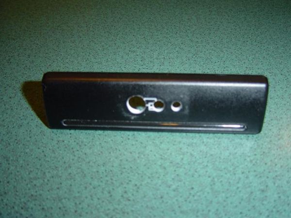
On the inside of the faceplate, break off any tabs that were not removed in the drilling. There is no need for any of these. Make sure you keep the tabs near the bottom edge that fasten the faceplate onto the tray. The result is this (sorry for the blurry shot).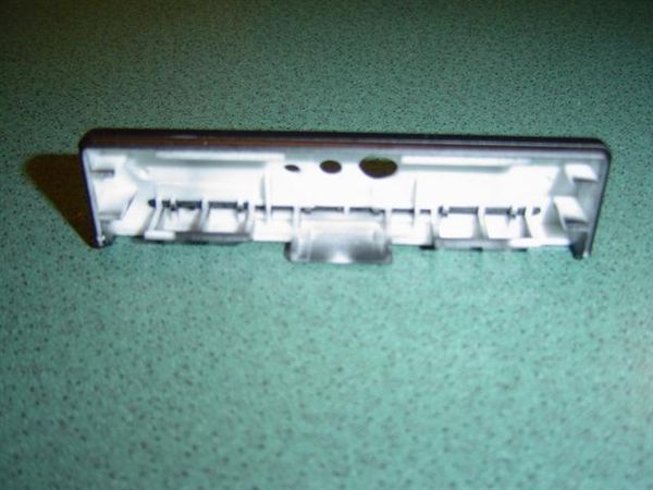
COIN TRAY MODIFICATION
Next, you need to remove some of the front of the tray to allow the lights and Mute button to reach the holes. VERY IMPORTANT TIP: Save the piece that was cut away for use later!!! I will explain later. I used a hacksaw to make the downward cuts, then a utility knife for the cut along the lower edge. You should not cut away too much of the front, since you need the grooves on the upper edge to remount the faceplate again later. I cut away a bit more than the width of the circuit board. If I had a Dremel, this would have been a bit easier.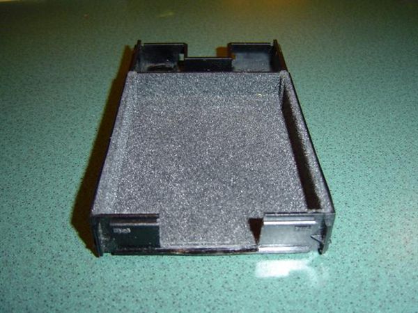
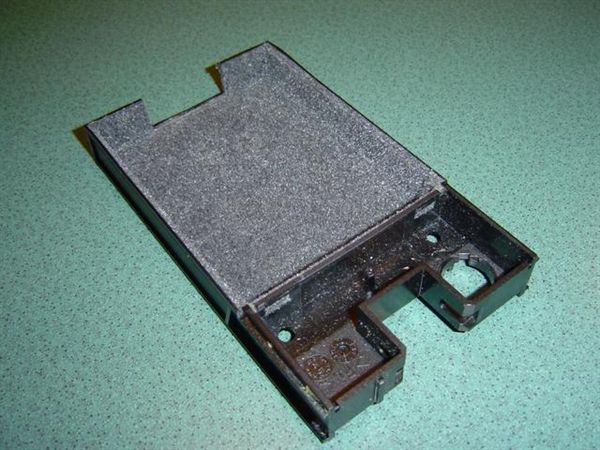
Some of the rear of the tray must be removed to allow the wires to run from the tray into the dash. Again, I used a drill and snips to open the top edge, but a Dremel would have made short work of this. The end result looks like this.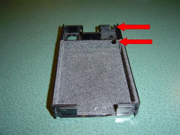
Okay, here is where we re-use the piece that was removed from the front of the tray. Turn it felt-side down with the raised lip edge toward the back. The plastic surface on top is a perfect for mounting the circuit board. If you did the holes correctly, the scrap piece of plastic is just the right height to raise the circuit board to the right height for the holes that you drilled in the faceplate. Remount the faceplate on the tray, and test fit the scrap piece under the circuit board to see how things line up. Use the raised lip edge along the back of the circuit board (kind of at an angle). Test to make sure that the Mute button works by pressing the button. You should feel it click. If not, simply enlarge the hole for the Mute button so it is clear of the edge of the hole.
Once you test fit and the Mute button works fine, mark where the circuit boards hole is located so you can drill for the screw to fasten the circuit board down. Drill a larger hole in the scrap piece that is under the circuit board, and mark exactly where the screw needs to be located. Use an awl or something fairly precise. If you miss drilling in the correct the location, the Mute button may not work properly, and require an even larger hole. I cannot remember the drill bit size, but use one that is smaller than the screw from the Smartcords housing. It will self-thread nicely into the hole you drill in the tray.
Next, fasten the circuit board to the tray with the scrap piece under the circuit board...you can tell that the felt bottom of the scrap does not slide on the felt of the tray. Using the screw from the Smartcord housing, screw into the hole you drilled in the tray. There is a bit of excess screw under the tray that needs to be removed. Use a hacksaw or Dremel to remove so the screw is flush with the underside of the tray.
The end result is this.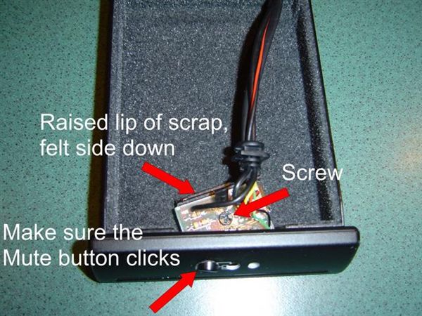
HOUSING MODIFICATION
Remove the electrical connector for the tray's light, which is on the back of the housing. Lift up on the clip, remove, and set it aside for reinstallation later. On the underside, remove the clear plastic bar that runs along the bottom of the housing (it is half covered by foil). This "carries" the light to the faceplate of the tray, but this may be discarded since you will not need the light anymore (I will explain why the clip needs to be reinstalled later).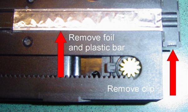
You now need to make an opening in the back of the housing to allow the wiring to pass through. It needs to be fairly large because of the in-line fuse holder in the Smartcord's power wire. Again, using whatever tool like a Dremel, make an opening in the back along the same line as the slots you made in the back of the tray itself. I used a drill and file to make this opening...again, wish I had a Dremel. Be careful not to cut into the mechanism on the housings bottom, and not interfere with the slots where the clip for the electrical connection is mounted.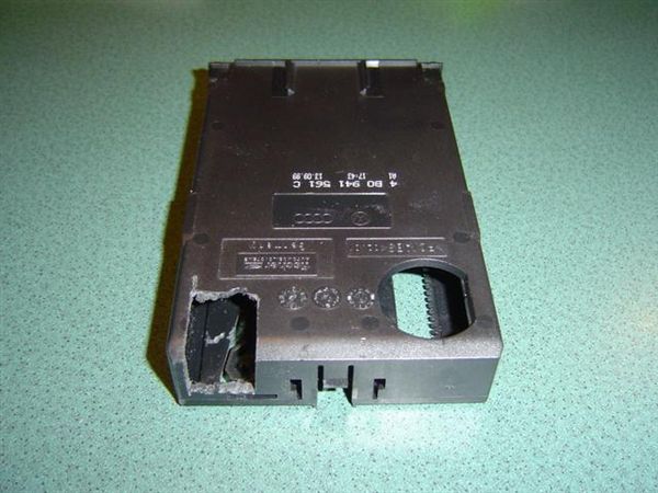
Now you are done with the modifications for the faceplate, tray, and housing. To reassemble, first run the Smartcord's two wires through the opening you cut in the back of the housing, and snap the tray back into the housing [NOTE: I did not reinstall the spring, since I did not want the tray to spring open if someone pushed the faceplate]. Close the tray, and place the Passport sticker on the faceplate. Make sure the Mute button still works. If not, realign the sticker. Reconnect the wire connector on the back for the coin tray light (again, I will explain the need for this later)
The end result of your hard work!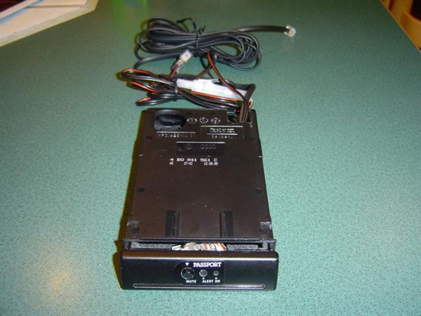
CUP HOLDER REMOVAL
First, you need to remove the radio, using the proper tools.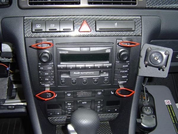
Then, remove the trim piece that surrounds the cup-holder and hazard switch. Then, using two radio removal tools, insert into the slots in the upper right and left of the cup-holder.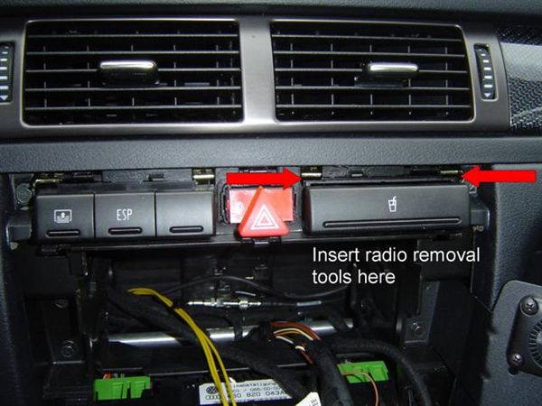
Unlike the radio, there is no snap to indicate that the unit is loose, just insert and pull the cup-holder out. Disconnect the wiring harness on the rear of the cup-holder. Set the cup-holder aside for future use if so desired.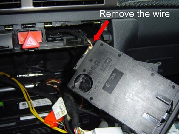
OPEN THE DASH PANEL
Sorry no pictures of this. But I will do my best to explain. First, remove the fuse panel cover. There are five bolts (8MM) that need to be removed: one to the right of the fuse panel, two on the lower corners of the dash panel, and two behind the trim piece that rests over the steering column. To remove the trim piece, simply slide it toward the rear of the car. Once the bolts are removed, the dash should drop down. Unclip the connections for the foot-well light and the VAG COM interface. Remove the panel from the car for better working space.
Remove the A-Pillar trim. See this post for steps on how to do this.
A-Pillar Removal
INSTALLATION
Run the wires from the Smartcord unit into the opening where the cup-holder was. Run the wires down through the space for the radio, and into the space under the dash. Connect the wire for the coin tray's light (which is useless, but it will prevent the wire from getting lost in the dash if you ever want to reinstall the cup-holder again). Slide the coin tray into the slot, and take up the slack in the wires from under the dash.
Run the wire for the radar detector (the phone plug) up behind the fuse box, then up the A-pillar and tucked along the headliner to the rearview mirror. Mount the radar detector in the desired location, and plug in the cord to make sure it reaches. It should be long enough to reach the center of the window with about 6" to spare. Then, tuck the rest in the headliner, or take up the slack under the dash.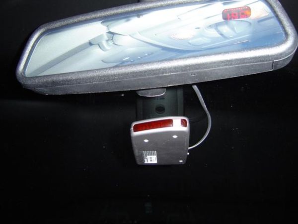
Use zip ties to fasten the wires to the other wiring along the A-pillar, and trim off the excess.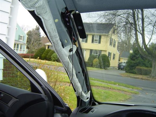
For a power source, I desired a switched circuit that was on only when the car was turned on. I opened the back of the fuse box, and tapped into the wire for the heated mirrors (fuse #8 in my car, check your Owner's manual for the location of that fuse). I used the tap provided with the Smartcord kit.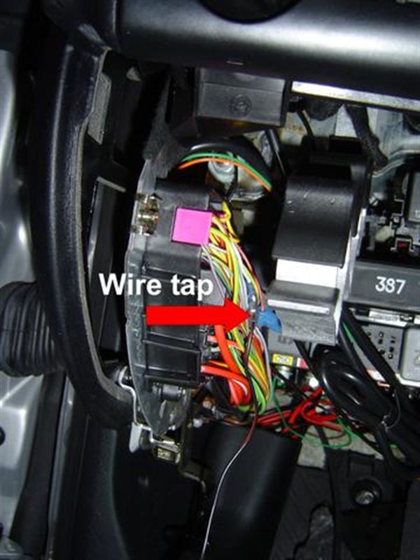
Disconnect the wire from the in-line fuse holder and installed the wires blade connector into the tap connector. Reinstall the back of the fuse box, and make sure that the wire hangs free so you can re-attach the wire.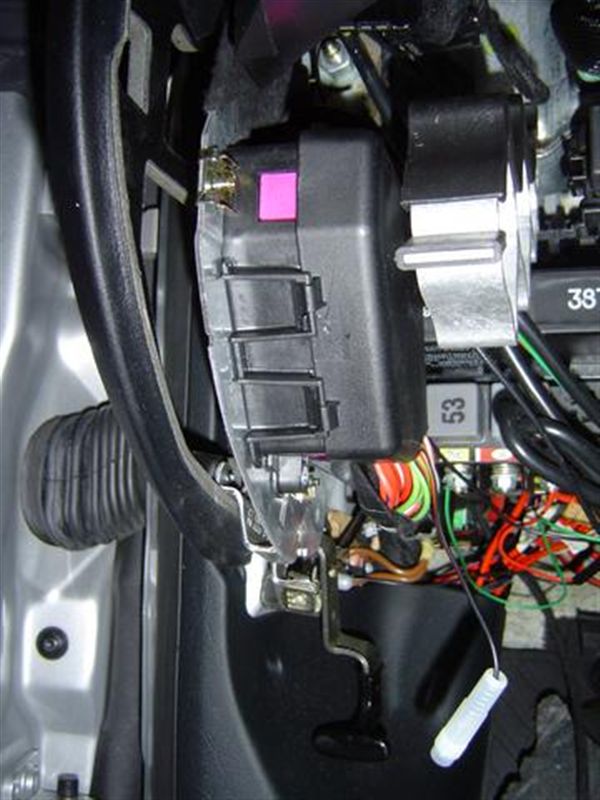
Fasten the ground (ring connector) to the metal bracket using the bolt shown here (NOTE: the ground I used for the phone installation is shown in the background, but the bolt is too thick for the ring connector that came with the Smartcord). Install the fuse and reattach the wire that runs to the circuit board.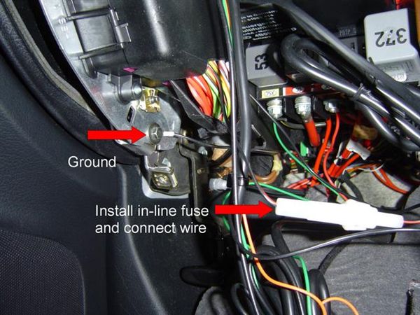
Check your connections, and test out the unit by turning the car on. Once you verify that everything works, reinstall the dash trim, the radio, the dash panel (don't forget to connect the wires for the foot-well light and the VAG COM), and the fuse panel cover.
Once all is done, enjoy your integrated radar detector. If the unit is switched to "dark" mode, the light in the dash will signal the alarm, and you will still get your audible signal. If desired, the Mute button is a short reach from your right hand. Enjoy!!!