You must be logged in to rate content!
11 minute read
CCV Replacement on 2002 530i M54
Compliments of Fudman @ www.bimmerfest.com
11-13-2009
Many thanx to Aioros, Cn90, Lbert, and others who have written extensively on this topic. Their writeups gave me the courage to attempt this myself. This DIY is specifically for M54 engines (2001-2003), which have not gotten the same attention as the older M52 and have some slight differences in procedure. This procedure is only for replacement of the CCV and hoses, and is specific to the insulated variant. Note: This procedure intentionally minimizes non-essential removal of components (i.e. intake manifold, oil filter housing, etc.). While space and access is difficult, it is not impossible. Removing things like the oil filter housing can improve access. It took me over 8 hours over two days to do this job but I took my time, documented everything, took pictures and was very, very careful. Knowing what I know now and following this procedure, I can probably do it in under 3 hours now. Absolutely NO technical knowledge of BMWs or auto repair experience is required (as I have very little of either). Caution is the key as there are occasional steps where things just don’t go simply or easily. I have developed workarounds for several of those. This procedure simply documents what I did and is for informational purposes only.
Tools
• T-40, T-27 & T-25 Torx
• 6mm, 10mm, & 13mm sockets
• Ratchet -1/4" & 3/8”
• Extension bars, various lengths - 1/4" & 3/8”
• ¼” drive handle
• Small mirror (absolutely necessary!)
• Assorted flat blade screw drivers in different lengths
• Magnetic pick up tool (optional)
• Small blade knife or cutter (for old hoses)
• WD-40
Parts
• 11 61 7 533 400 Pressure Regulating Valve - CCV (insulated)
• 11 61 1 533 398 Vent Pipe (insulated)
• 11 61 7 533 399 Connecting line (insulated)
• 11 61 7 532 629 Vent hose (insulated)
• 11 61 7 504 536 Return Pipe (insulated)
• 11 43 1 740 045 O-Ring, Oil Dip Stick Tube to Oil Pan
I should’ve replaced the throttle body gasket but they didn’t have it in stock and I didn’t want to wait to button her up. Oh well! Note that the RealOEM part #6 vacuum hose is not required. In fact, the connection point on the insulated CCV is capped and hidden under the foam jacket.
Here is what I did:
1. Undo the long spring clip to remove the filter housing cover and and the cabin air filter. Squeeze and remove the small spring clip on the bolt at the front housing support. Remove the sensor connector and then remove the filter housing by pulling forward and store
2. Remove the fuel rail cover by removing the (2) plastic caps and the (2) 10mm bolts underneath the caps. Remove the fuel rail cover and store.
3. Remove the Mass Air Flow sensor (MAF) (Ref. Bentley 130-33) by disconnecting wiring harness to MAF sensor (push down the metal clip and pull the connector). Loosen the hose clamps (6mm or flat blade) between MAF and upper air intake boot and the air filter box. Remove the MAF to give you the space to remove the air filter box (next step).
4. Remove the air filter box assembly. Detach wiring harness behind air filter box
Remove 10mm bolt on air box base. Remove both air filter box and reassemble the MAF and air filter box as a single unit. Note the air filter box can be difficult to remove without removing the MAF because of insufficient space to pull the components apart.
5. Remove upper air intake boot by loosening the hose clamp (6 mm or flat blade). Carefully disconnect the vent hose coming off the top of the upper air intake boot. This took me over 20 minutes of gently prying the elbow off with a screwdriver to avoid damaging the boot. Maybe I should’ve just yanked on it…
6. Remove the lower air intake boot by loosening the two hose clamps. Some DIYs say that you must replace the lower intake boot. I didn’t want to spend the extra $35 so I was careful not to damage it during removal. Access to the second hose clamp screw requires removing a small cable support (10 mm bolt). Note that the boot has a large rubber tab at its base. This tab aligns with guides located on the throttle body port. Align the tab with the guides when reassembling.
7. Remove the oil dipstick guide tube by cutting off CCV hose from the dipstick (it’s much easier than removing it!). Remove the 13mm bolt holding oil dip stick bracket. Disconnect a wiring bundle from the support bracket. Replace the O-ring at its base. No oil will spill as long as the oil pan is not overfilled. Insert a plug (I used tin foil) on the hole to prevent anything from falling in. Clean the guide tube going to the CCV with a flexible rod and clear with compressed air. If you drive in cold weather, you will probably find yellow-white oil condensate (“mayo”) inside this tube. This is why you are changing to the insulated CCV.
8. Remove the wiring harness box by removing (1) 10 mm bolt and (2) 10mm nuts. One of the nuts is located at bottom right of the throttle body, next to one of the throttle body bolts. Use a mirror to view the location. The wiring harness connectors have a metal locking wire clip. Push down and pull on the connector to disconnect. To re-install, insert connector without touching metal clip until you hear it click into place. Several cables leave the front of the wiring box. Disconnect those electrical connectors that terminate toward the front to allow freedom to move the wiring box to the rear. Label all connectors to simplify reassembly. One cable has three connectors, one at the top of the radiator and the other two connectors at the front right of the radiator. Tie the two connectors together with a 24” string before you pull them to get slack. The string is so you can pull them back through when you’re done.
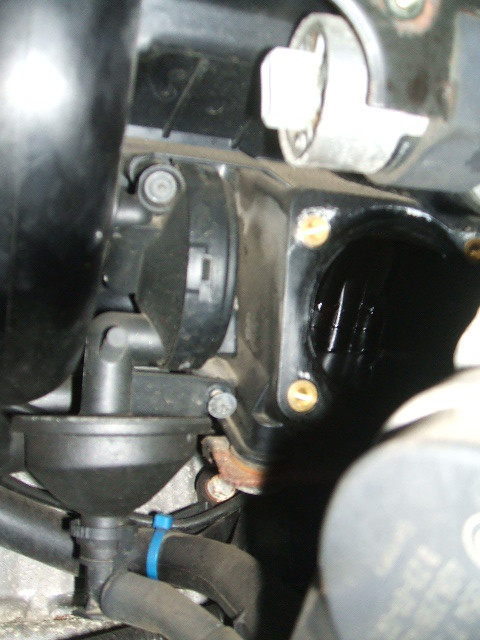
9. Remove the throttle body by removing (4) 10mm bolts on the corners of the throttle body. Move it aside (to the rear) to access the CCV.
10. Remove (2) T-25 screws that hold the CCV in place. Then cut the hoses to allow removal of the CCV. When removing the old hoses from their connection points, it is far easier to simply cut or break the old locking rings with a screwdriver than to try and squeeze the locking rings to remove them. Once the locking rings are broken, simply pull the hose off. You will find most of the hoses to be somewhat brittle, which is why you are replacing them.
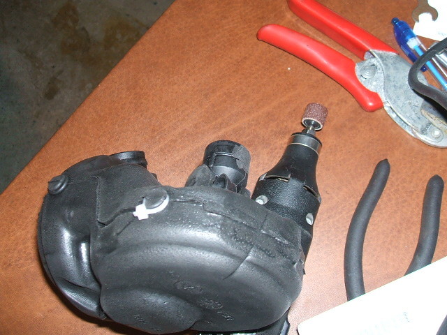
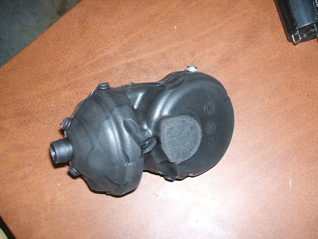
11. Warm weather uninsulated CCVs can skip this step I installed the insulated CCV and there is barely room to put it into place due to the foam insulation jacket. Since the connection to the connecting line requires that you rotate the CCV to lock the connection, I decided to modify my insulated CCV by cutting off about 1/8” of the foam jacket on the flat circular disk side of the CCV with a razor. I did not cut through the foam jacket, I just removed enough of the foam so the surface is flat (see photo). This creates enough room to rotate the CCV when in place. This makes a HUGE difference.
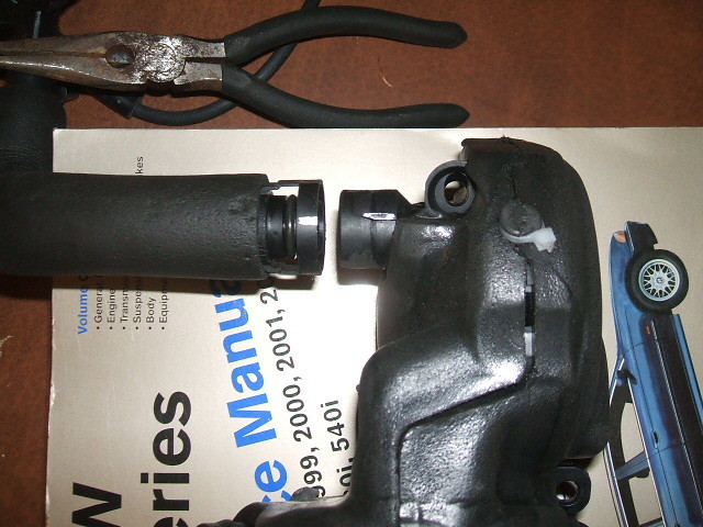
12. Installing the connecting line is the most difficult. It requires you to rotate the line about 1/3 turn to lock the line onto the CCV (practice this connection process on the bench). The other hoses use the locking snap connectors that just insert and snap to lock. After trying for over 2 hours to assemble these parts in their location , I was unsuccessful and decided to modify the locking mechanism. Use a Dremel tool and a sanding cylinder to sand the two retaining ridges on the CCV nozzle smooth from about 1” long to about 1/3 inch long (see photo). This simply reduces the rotation required to lock the connecting line to about 1/8 turn (~45 degrees). Mark the spots with paint where the connecting line aligns with the CCV nozzle to aid in assembly (see photo). Insert the connecting line into the original position from above the intake manifold. Much wiggling and bending of the line is required to get it into place. Once the lower connection is in place, insert the CCV into place. Align the marks, insert the hose into the CCV and rotate the 1/8 turn. This whole process took 10 minutes (vs. over 2 hrs!) with a minimum of effort after modifying the parts! Insert the upper connection line to the engine nozzle until you hear a click. Insert the CCV screws and tighten.
13. Remove the old hoses and install the new return pipe to the top of the engine. The other end attaches to the small branch nozzle at the top of the connecting line. Insert each hose connector onto the connecting nozzle until you hear a click.
14. Remove the old vent pipe and insert the new vent pipe down into the same location. The 90 degree turn is at the top and the angled turn is at the bottom. Align the lower vent pipe connector to the lower CCV nozzle, insert and push until you hear the click. The upper vent pipe connection connects to the valve cover in the same way.
15. Work backwards from Step 9 and it is clear sailing from there. When reconnecting the wiring cables, pull the string to pull the connectors out from the radiator. Be sure to route cables so they are not exposed to the fan. Make sure the right cable goes to the right connector.
16. Prepare the oil dipstick tube by inserting the vent hose onto the branch muzzle on the dip stick tube. The vent hose does not use a locking ring and simply inserts onto the nozzle. When reinstalling the dip stick, you must make sure that the one connector that is attached to the wiring box (all others are cables exiting the wiring box) is disconnected to allow you access to reconnect the upper end of the vent hose to the bottom of the CCV. Insert the hose connector onto the CCV nozzle until it clicks.
When I was done, there were no parts lying around (a good sign). I fired the car up, she purred like always and no CEL lights were lit. A short drive confirmed that I didn’t screw anything up. I don’t notice any difference in the way she runs but there was nothing wrong before the change. Hopefully, I won’t be blowing the black smoke that I had last winter. Hopes this helps someone who does this job on an M54.