You must be logged in to rate content!
5 minute read
Lockpick Installation w/Pics
Compliments of wbond @ 200forums.com
I searched through the threads and didn't see any that had pics of the installation so I thought I would put a few up. I have installed this many times on my grand caravan and it is significantly easier on that than the 200.
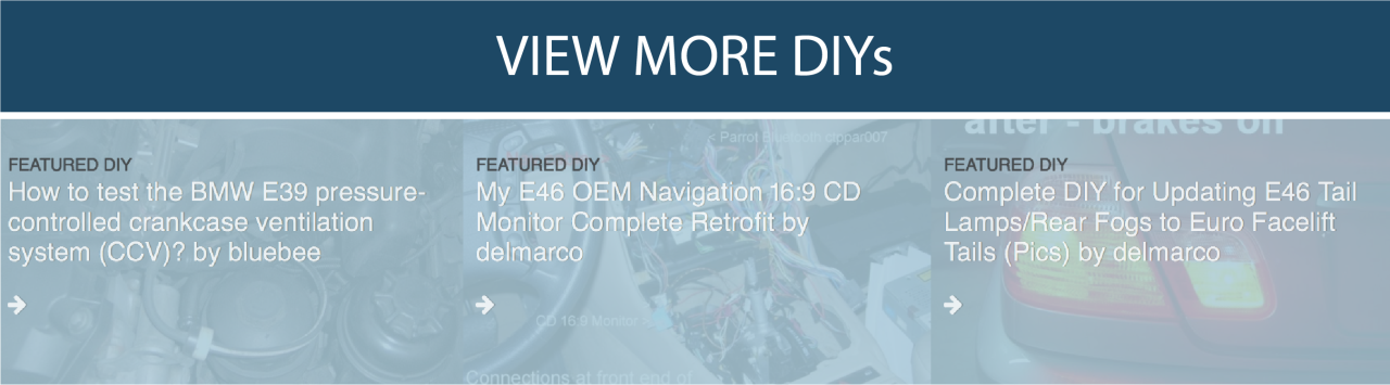
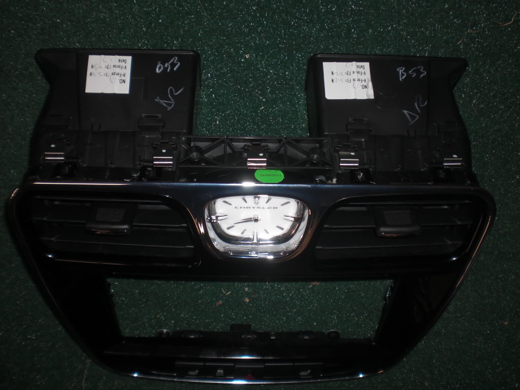
Anyway, in order to remove the center bezel around the radio, I used a fiberstick to pry/pull this off. There are four main trim attachments on this piece, one on each side of the radio and then one on each side slightly lower and inboard of these. Try not to pull near the vents as they are held on with four flimsy tabs, two on top and two on bottom. Also along the top edge there are 5 tabs that will need to disengage once you get it pulled out a little. There will be two connectors to disengage from the bezel, one for radio and other for the bottom switchs.
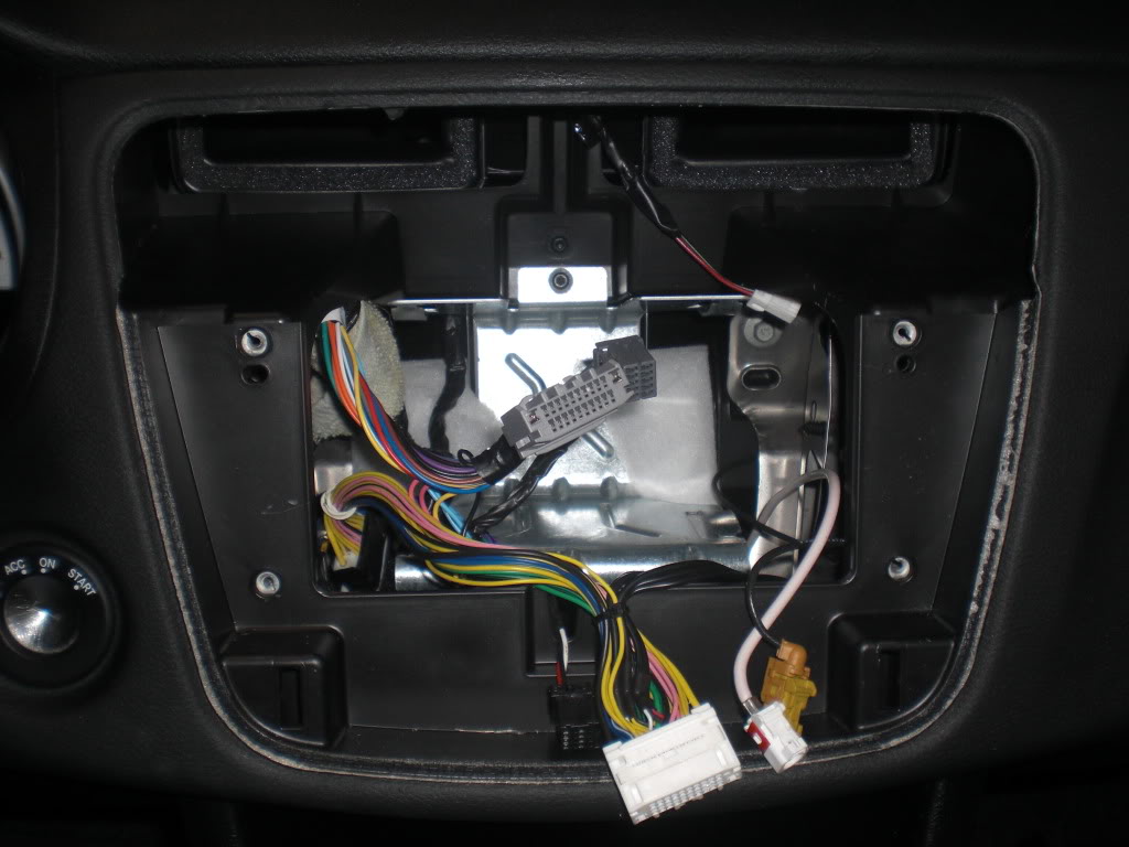
Once this is removed, the radio will be held in place with four torx screws, I believe T20. Remove these and now you can pull the radio out, it will be a little snug. On the back, there will be a large gray connector, small gray connector and two coax antenna connectors (There is no white connector from the main vehicle wiring). Disconnect these and remove radio. Now you are ready to install the lockpick harness. There will be a long branch from the pigtail harness that connects to the lockpick module. This can be fed through the IP bracket on the left side down to the driver side footwell area. If you are adding rear camera, it is easier to tape this to the main bundle and snake it through.
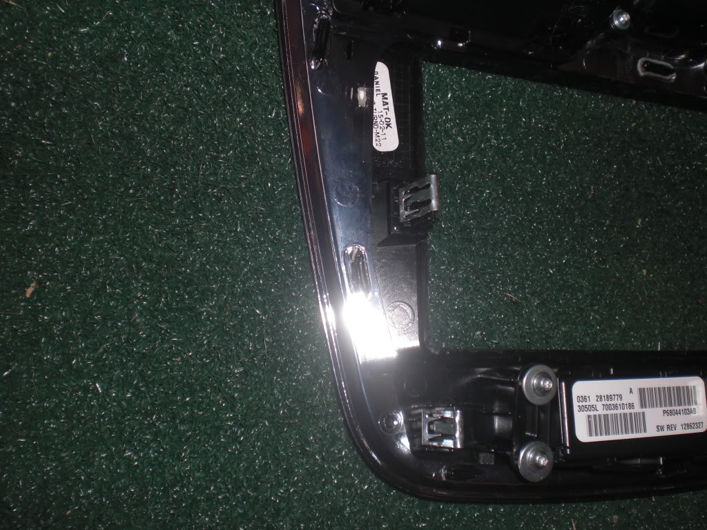
See opening on left side in pic below.
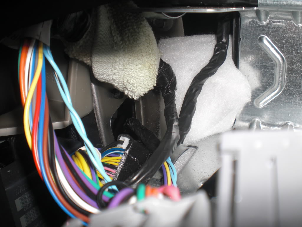
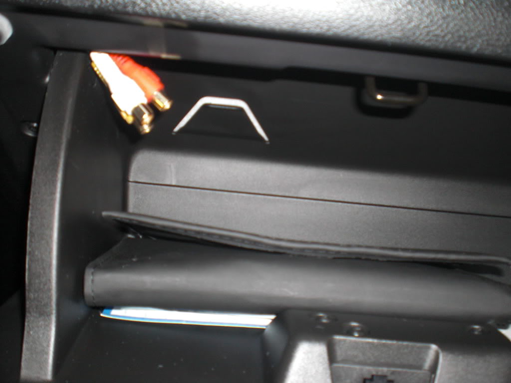
The harness will have aux inputs and outputs. These can be fed into the glovebox. There is a piece of white foam on the right side of the opening, you can pull this up and feed the connectors in there.
See white foam on right side of pic.
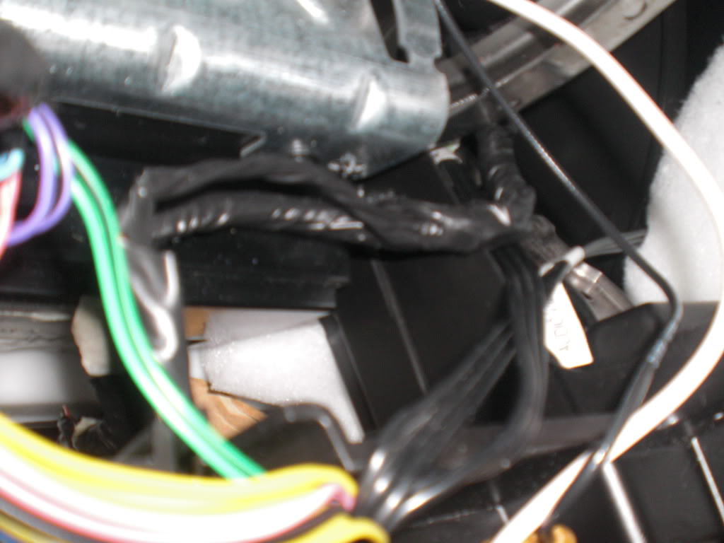
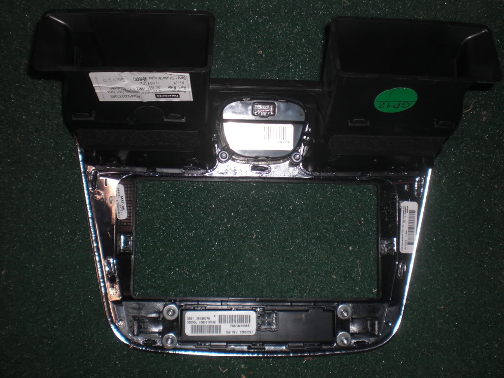
There is some dead space directly below the radio opening behind where the switches are. You can store the excess wire length and connections in here and on the left side where the main bundle went down to the footwell area is where i put the unused white connector.
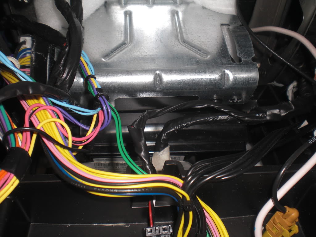
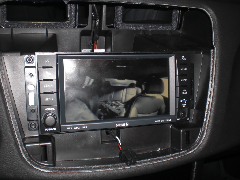
No you are ready to reconnect everything. Make sure you now connect the white connector to the radio as this is where i believe the camera feeds are located. Once this is done, test all functions before reinstalling the trim piece. I don't have my rear camera installed yet, but i did try it out and you can see the inside of my vehicle in the pic.
To store the module, there is some dead space behind the lower trim under the steering wheel or directly behind the center of the IP. You want to be able to access this in case of any updates that will be done through the usb connector. I don't have mine stowed yet because i have to install my rear camera still. It is actually wrapped around and sitting in the center console bin. Gives you an idea of how much excess wire there is.
Keep in mind, the IP bracket is very sharp, make sure you cover the wires and connectors to prevent any cut ckts and also minimize any bsr possibilities.
Pay attention to the lockpick settings for the dip switches. This vehicle is a low speed system. All functions worked as expected, rear camera comes on when in reverse, gps input while in motion, view video while in motion and sports button on the travel link works while in motion