You must be logged in to rate content!
13 minute read

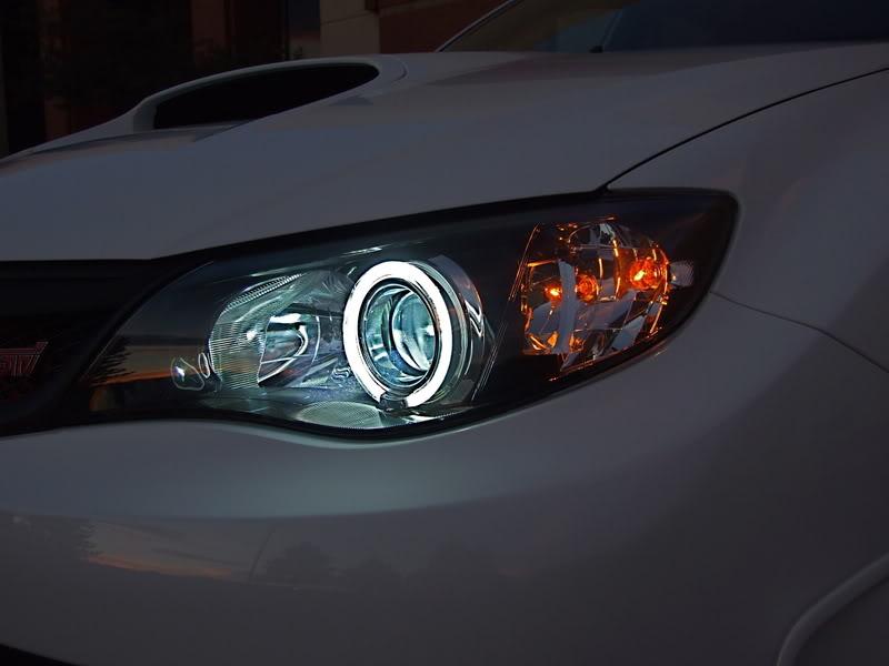
DIY Angel Eyes 2008 WRX/STi
Compliments of Spaceman @ www.iwsti.com
9-2-2008
DIY Angel Eyes 2008 WRX/STi
Time Needed: 4-5 Hours Total - First Time
Difficulty Level - 1 Being Easiest - 10 Being Hardest - I would rate it a 6.5. Basically just time consuming, although it can be a bit intimidating for people opening up headlights for the first time. Anyone can do this, just follow the instructions.
Items Needed:
1 LightWerkz 105mm Angel Eye Kit
Oven
Flat Head Screwdriver
Philips Head Screwdriver
10mm socket and socket wrench
Drill
¼ Drill Bit
½ Drill Bit
J-B Kwik Weld - 1 Pack
Masking Tape
Electrical Tape
Soldering Tool or T-Taps
Razor Blade/Knife
Towel
Air Duster
Prying Tool (optional)
Needle-nose pliers
Before you can begin working on these headlights you first need to remove them from the car. To do this you need to remove your front bumper which can take 10-20 minutes. Follow the bumper removal how to and return here once the bumper is removed.
http://www.iwsti.com/forums/how-inst...r-removal.html
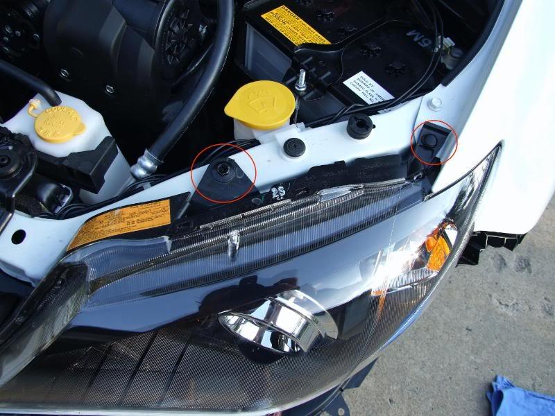
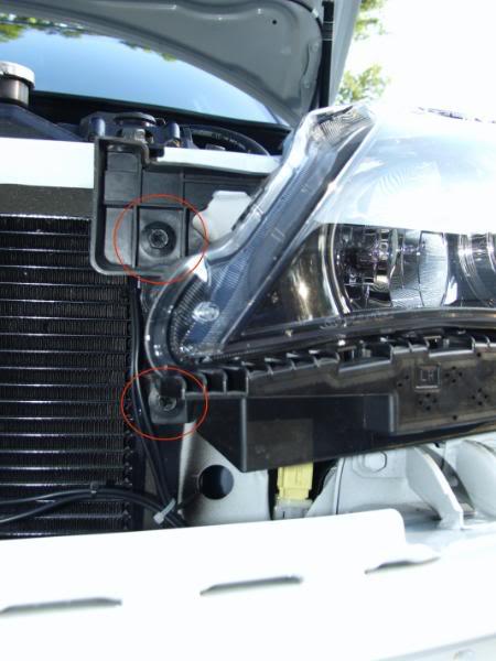
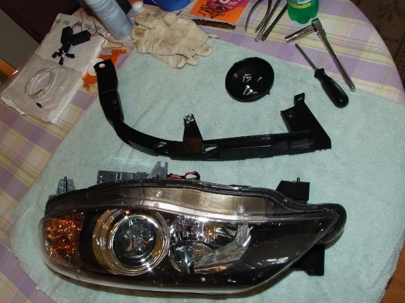
There are a total of (5) screws and (1) clip holding each headlight to the car. Remove the clip and the screws, and then pull out the headlamps and unplug the wire harnesses.
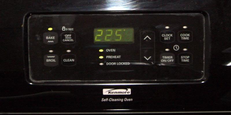
Pre-heat Oven to 225 degrees Fahrenheit.
**WORK ON ONE HEADLIGHT AT A TIME**
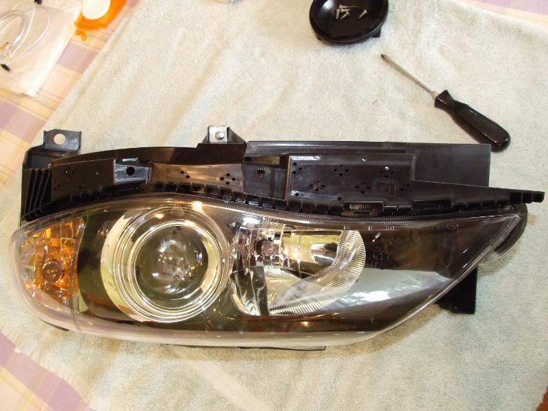
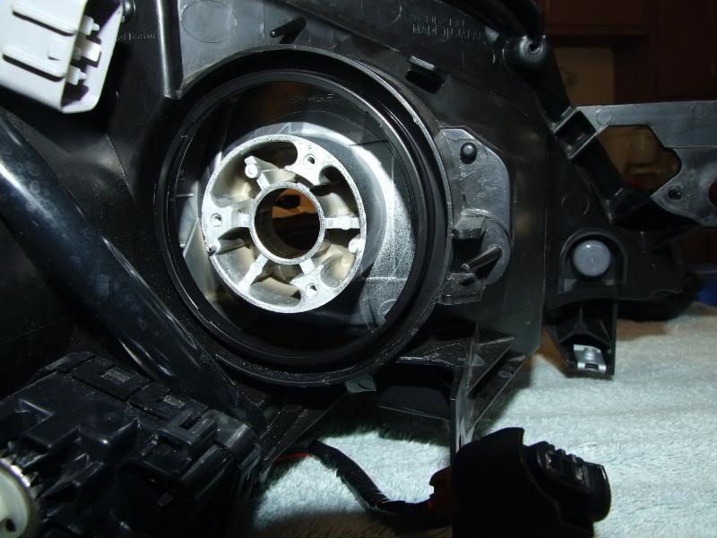
Remove the plastic cap in the back of the low beam headlight. Simply twist to get it off.
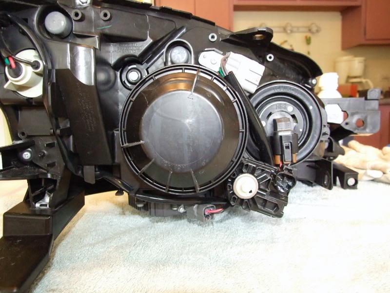
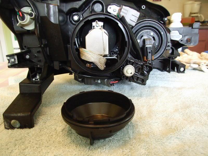
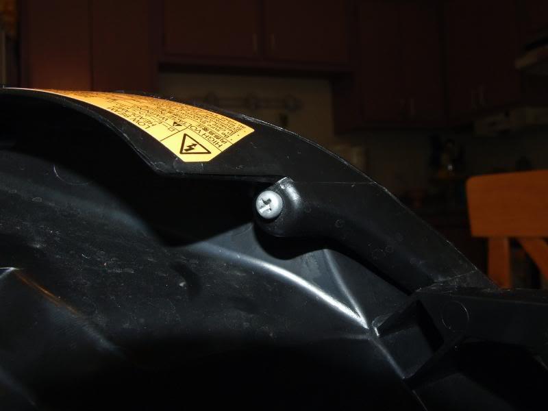
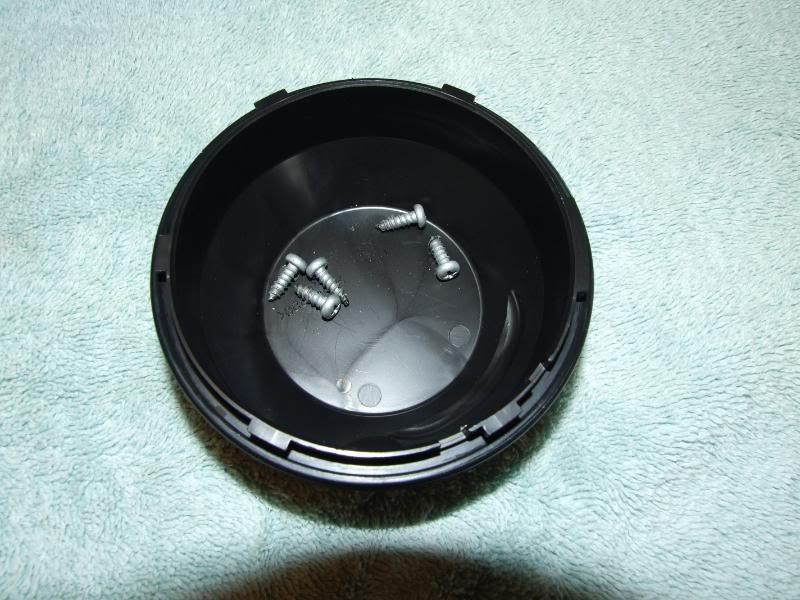
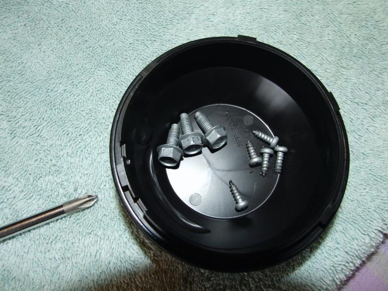
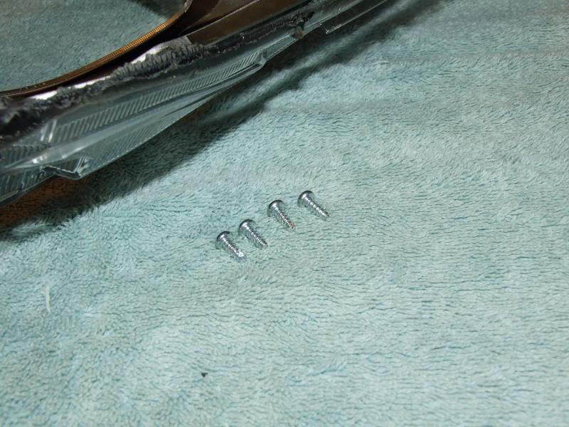
Remove the (5) Silver Philips head screws on the back of the light and place them inside the low beam cap for safe keeping.
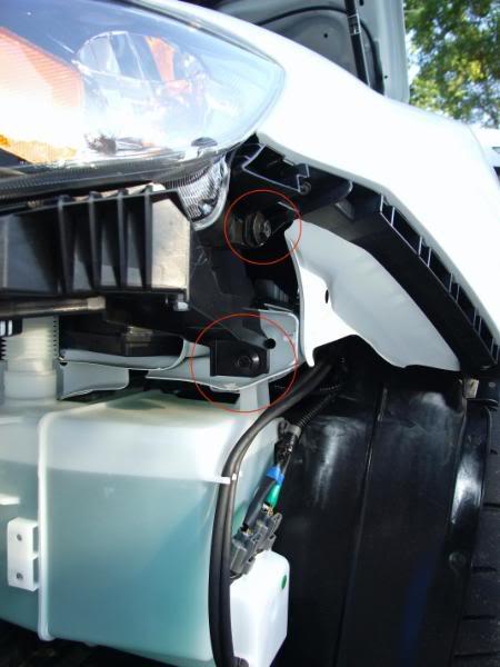
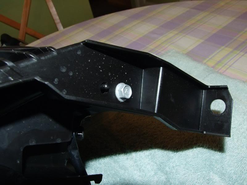
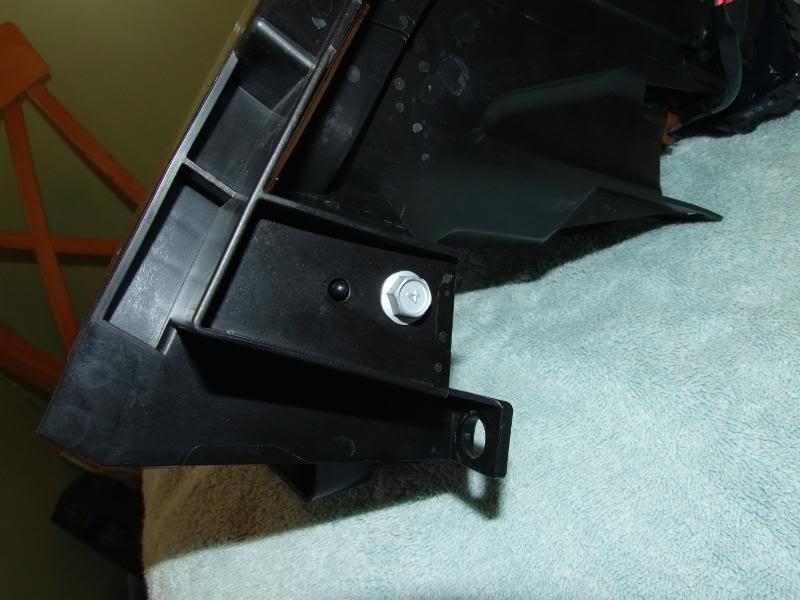
Remove the lower plastic beam that is below the light. It is held in place by (3) bolts. Place the bolts in the cap.
Once the oven is preheated, place the lamp inside for 10 full minutes.
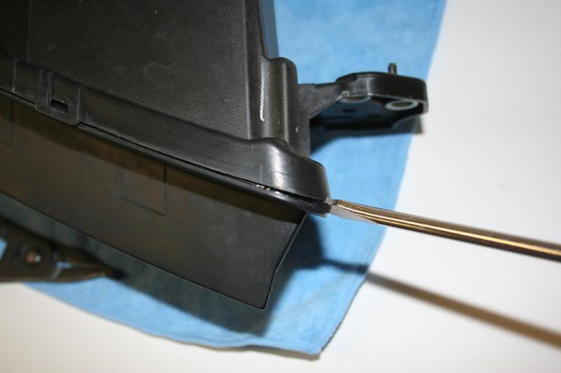
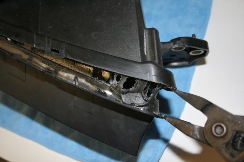
Take the lamp out and place the lamp on a towel face down. Use the flat head to lift up the tabs holding the lights.
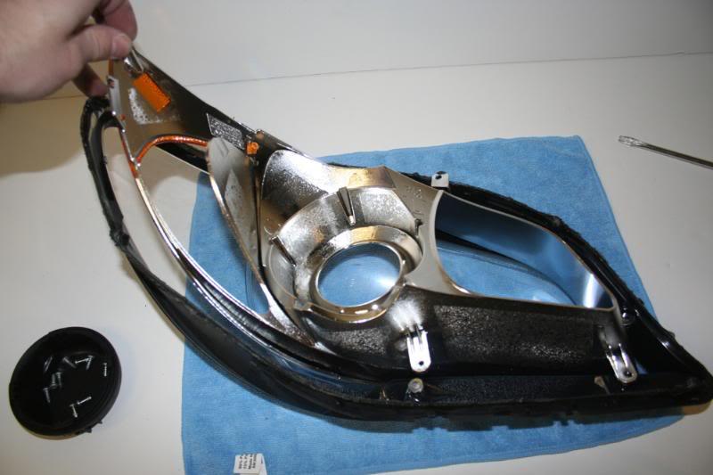
Then use a flat head screwdriver to begin separating the two halves of the lights. If you have a prying tool, use it, this comes in handy! Go all the way around and pull apart the two halves. Put the rear housing on its side and put it away for the time being. Place the front (clear) half face down on the towel.
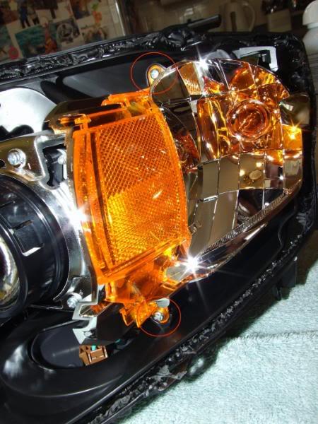
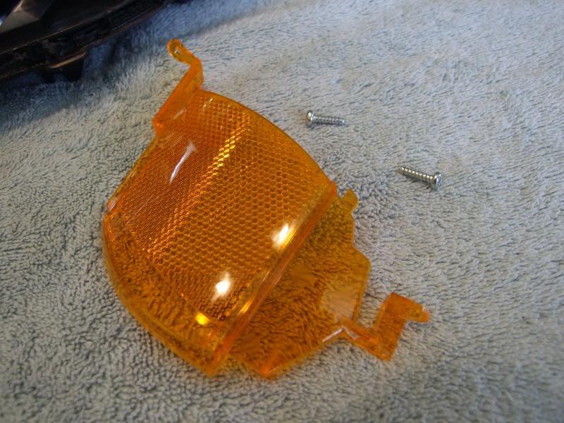
Now that you have the two halves separated you can clear out your lamp by removing the orange reflector if you want. It is held in place by (2) screws. Be sure to put the screws back in once you pulled out the reflector.
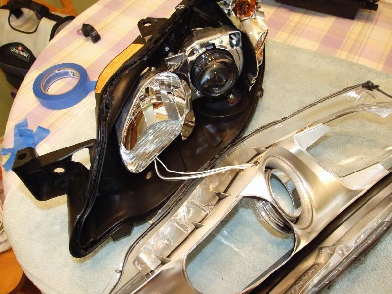
Next remove the (4) Philips head screws holding the inner housing to the lens and place these in your cap so you don’t lose them.
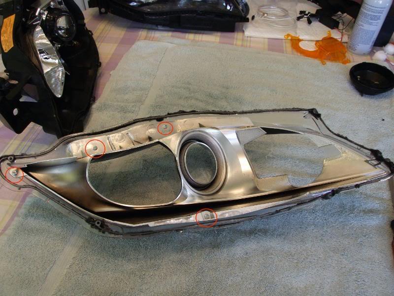
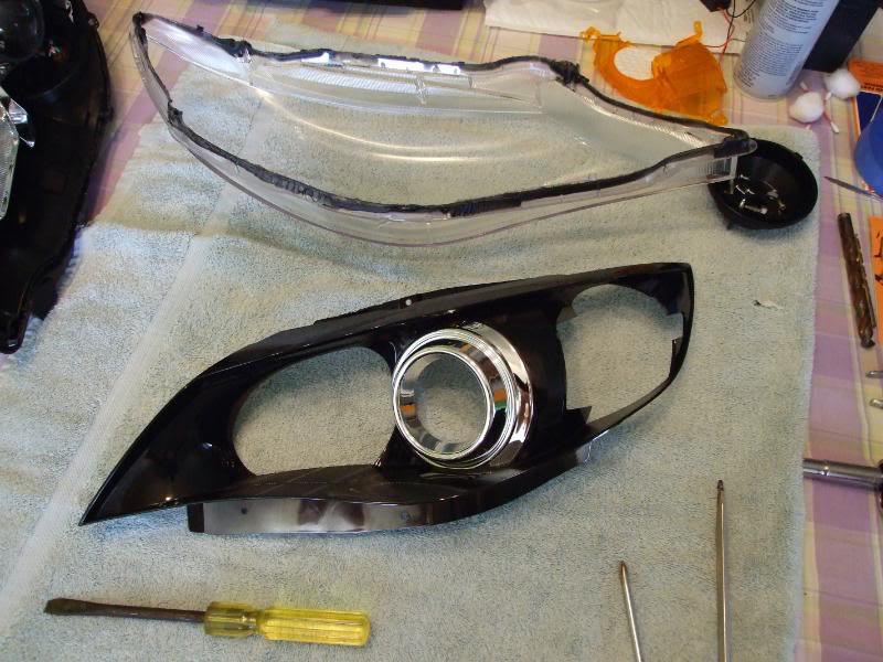
Pull out the inner housing from the lens. Be careful not to touch the black sealant as it is sticky. Put the clear lens to the side, as we will be working with the inner housing.
Now you have a choice;
#1 You can drill a ½ hole to allow you to pass the wires and connector through.
#2 Or you can cut the wires from the halo in half so that you only need to drill a hole big enough to feed the wires through. After you pass the wires through you can solder/reconnect the wires back together.
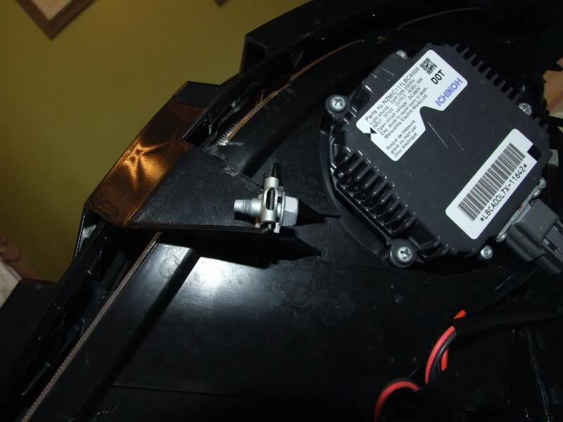
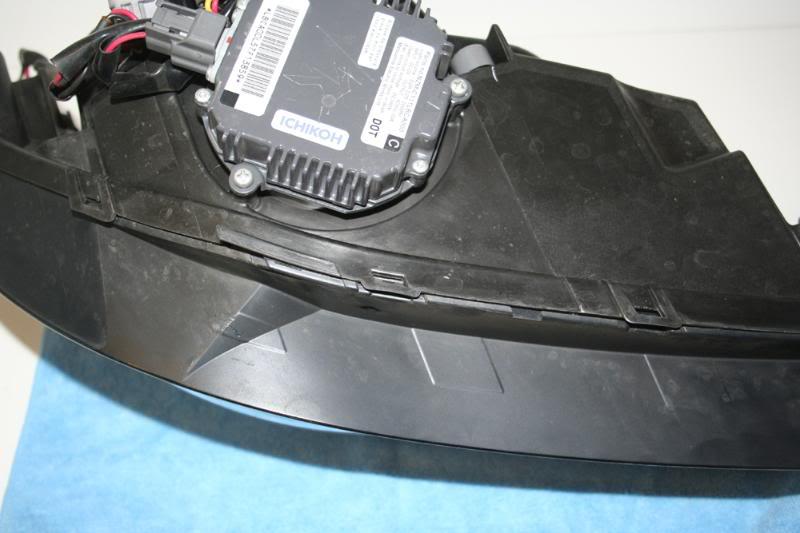
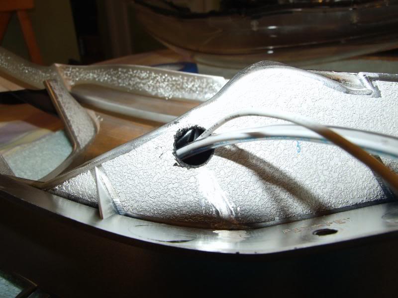
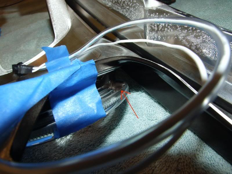
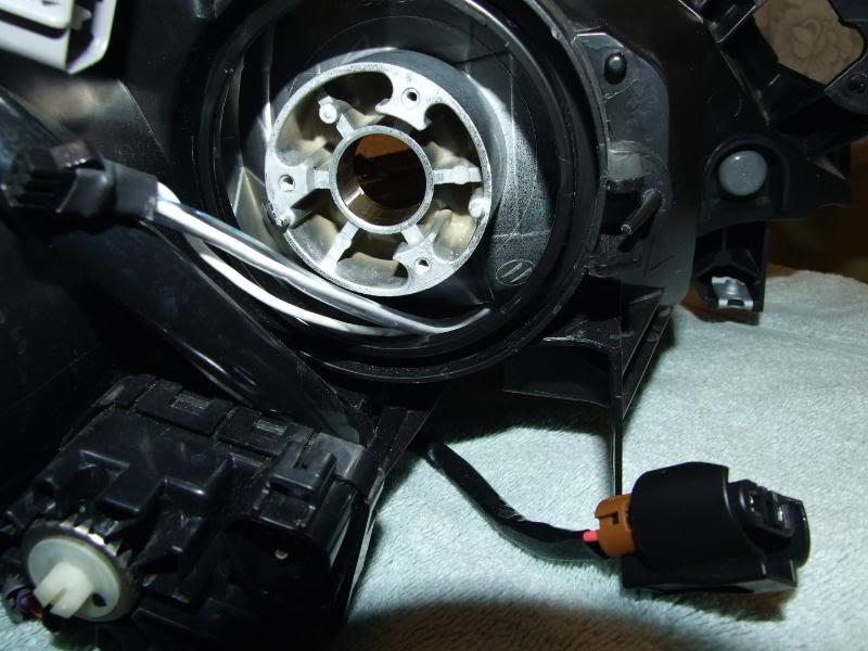
I chose not to separate the wires and I drilled a big enough hole to pass the wires with the connector through. The bottom of the halo pretty much covers up the hole and the hole isn’t visible once the lamp is put back together.
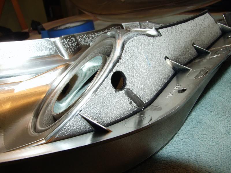
Take a look at the picture below to see where I drilled the hole. As you can see it is on the bottom of the inner housing and it is as far back and close to the edge as I could get it.
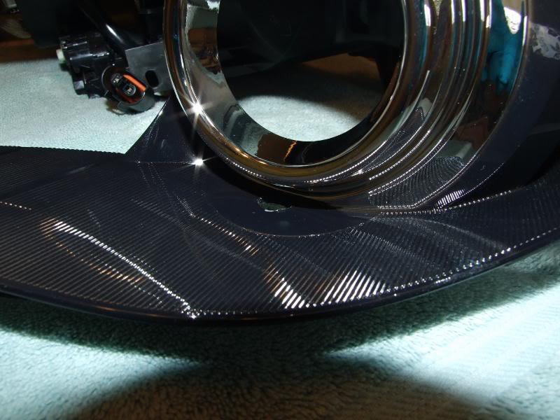
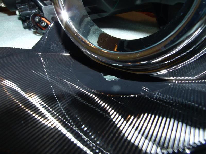
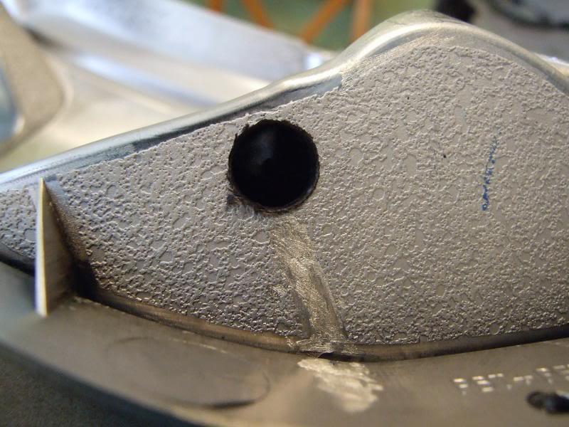
If you choose to drill a ½ hole be sure to use a smaller drill bit first to make a small pilot hole. Also drill carefully and don’t put to much weight on the drill as not to come through the other side and damage the low-beam light chrome surrounding. Use some compressed air to clean up the housing and blow away the plastic shavings from the drilling.
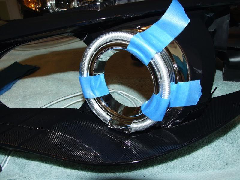
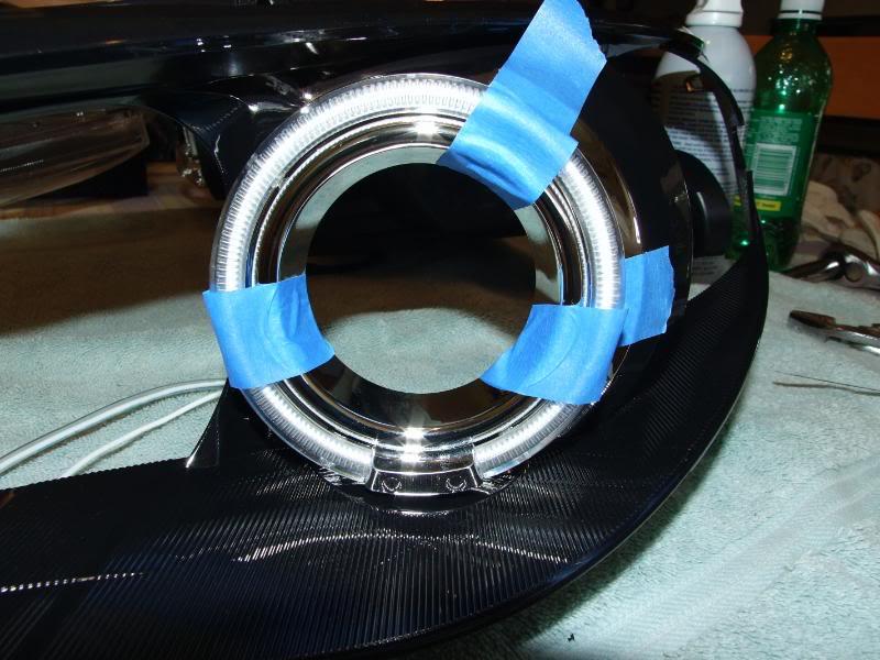
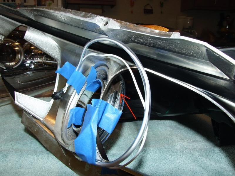
Now grab one of the halos and feed the wire through the hole. You may need some needle-nose pliers to help you pull the connector through the hole. When pulling the wires be careful not to damage the connector.
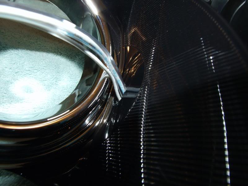
Line up and adjust the halo so that it is sitting straight and even. Tape it down to hold it in place. I also tapped down the wires in the rear so that the wires would be held in place and be out of the way.
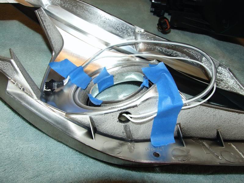
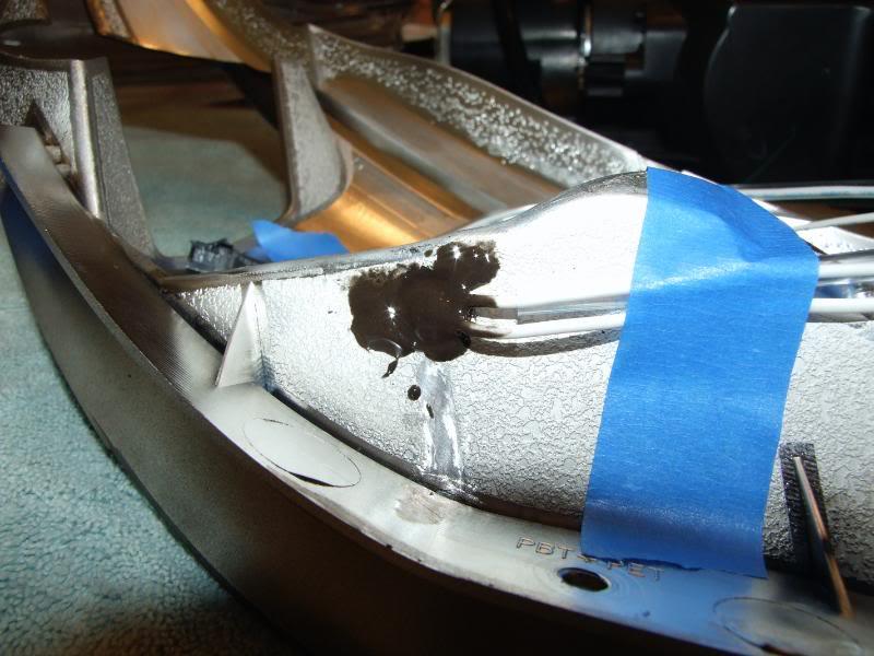
You are now ready to secure the halo to the housing. Make a note of where I applied the J-B Kwik Weld. You don’t need much and you only want to apply it in the (2) spots shown. You don’t want it to be seen when the lamp is back together. I also applied some to the bottom of the housing where I fed the wires through. This isn’t a must but I wanted to cover the hole up. Mix up some J-B Kwik Weld with a ratio of 1:1. You don’t need much and this stuff dries really fast! Give the JB about an hour to dry. You can start working on getting the other lamp started in the meantime.
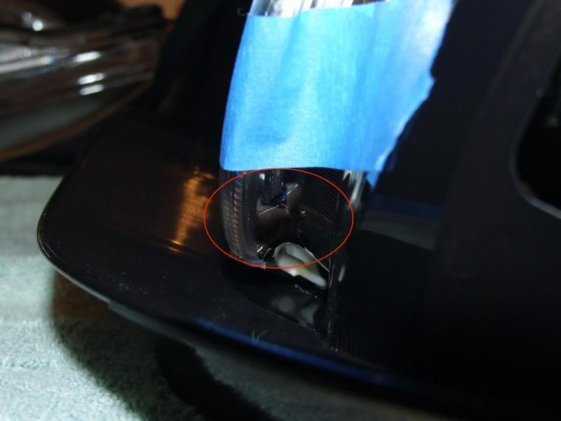
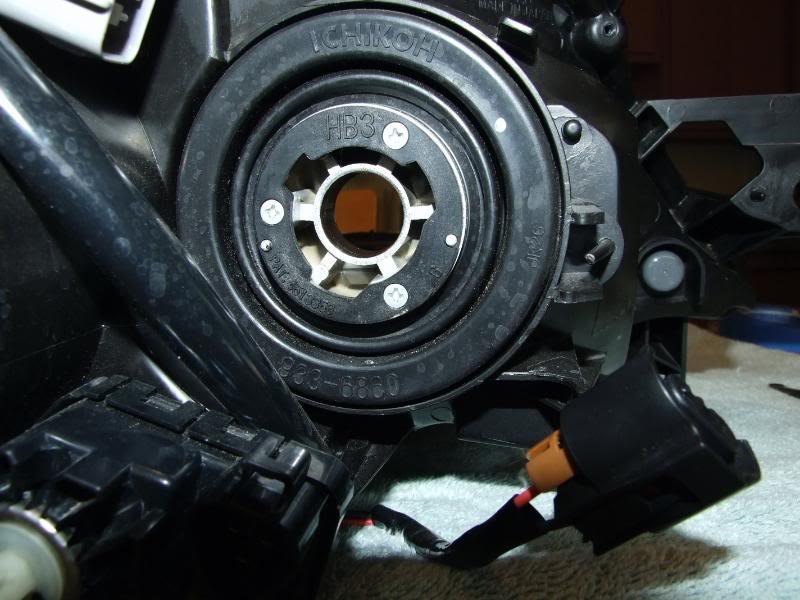
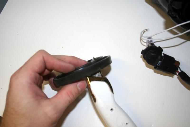
Next you want to remove the rubber cap in the rear of the high-beam light. But first you need to remove the high-beam (HB3) light.
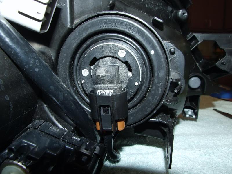
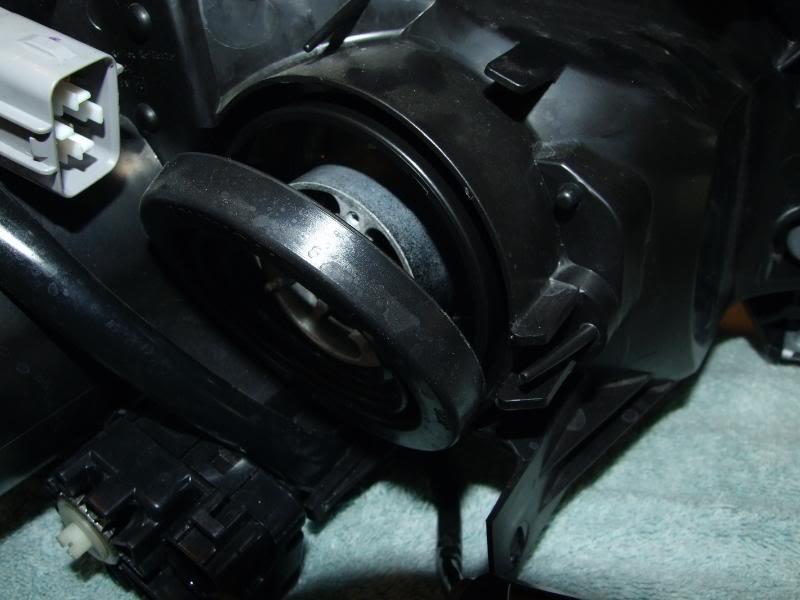
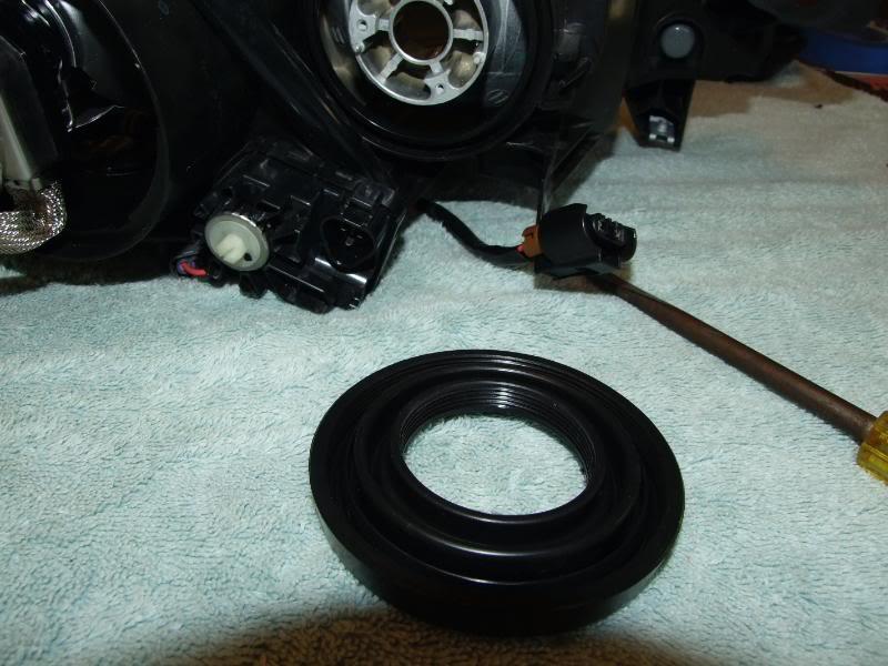
You will need to make a small cut in this rubber cap because you will need to run the wires through here.
Pre-heat your oven to 225 degrees again if it hasn’t been on this whole time. Once the oven is preheated you will need to put both halves of the lamp in the oven for 5 minutes to soften up the sealant.
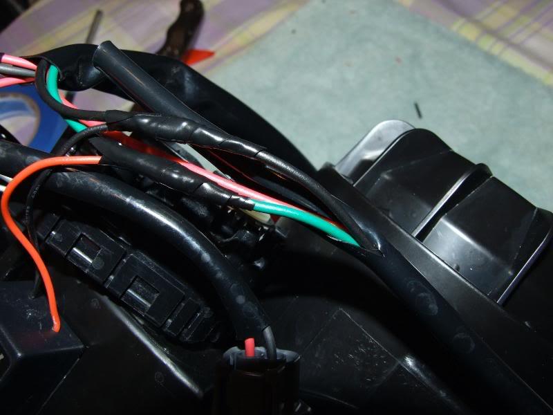
Once you take both halves out of the oven you will be putting them back together. As you are putting them together make sure to run the wires through from the halo, see below.
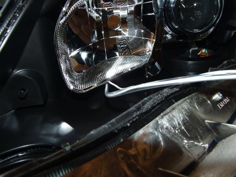
As you are attaching the two halves of the lamp make sure it is aligned and clip back all the tabs. Push down all around the lamp to get a good seal. Once it’s all together use the (5) Philips head screws that we removed to really fasten the halves of the lights together. Once you get all of them in, place the complete lamp back in the oven for 5 minutes. This extra time allows the sealant to spread out, eliminating any small air leaks.
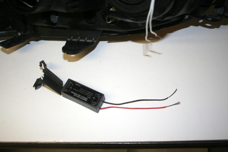
After the final (5) minutes in the oven you are ready to tap into the parking lights for power. Cut about half the length of the wire off the power and ground wires.
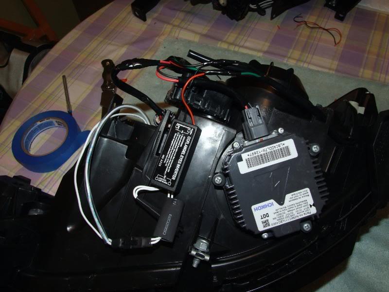
Find the parking/turn signal lamp and trace the wires (Black and Green). Cut off the black covering, and make some space. Strip off some portion of the wire so you can tap in for power. If you have t-taps you can use them, this method works too. The Black wires goes to the Black and the Red wires goes to the Green. Use some double-sided tape to mount the inverter to the bottom of the housing.
That's it!
Props to Caesar from LightWerkz.net for offering this product and letting me create this how to using his format and some of his pictures.
Do this at your own risk. Comments are welcome.