You must be logged in to rate content!
16 minute(s) of a 25 minute read
1-9-2013
Jeff's winter 2012 20v engine build
Compliments of burdickjp @ club4ag.com
1-9-2013
I have a month or so off betweeen semesters at engineering school and thought I'd finally put some effort into a 4A-G of my own. I've been sharing it on some 4A-G communities looking for some feedback and encouragement. Please, let me know what you think!
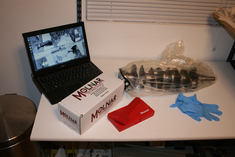
The build started the day I got home from a semester away. I pulled some parts out of storage and let them sit and equalize in temp before continuing. The crankshaft I'm using is one of three 40mm crankshafts I have at my disposal. Right now it looks to be the best candidate for this build.
My measuring methodology is rather ritualistic. I measure each feature a minimum of 9 times, three each in three directions. All of my instruments read to 1 micron ( 0.001mm ). All three measurements in one direction must come out within a micron of eachother. If they do not I keep measuring until they do. I really wish I had a CMM for this. It'd be more accurate and a hell of a lot faster.
This info goes into a spreadsheet. If Toyota specifies a tolerance this autopopulates. If there's a corresponding size designation this autopopulates. When I have mating features done it will pick bearing sizes and give me clearances. I can shuffle bearings around to get more precise clearances. Once I know my sizes I order them up from Toyota, then measure the actual bearings that come in, shuffle them around, and do a final install and plastigauge.
Here is Jeff's wicked-awesome engine blueprinting spreadsheet 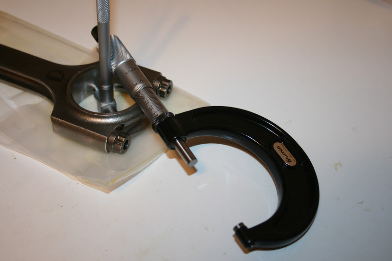
These are Molnar Technologies 40/20 rods I'd put together a while ago. These will allow me to pair that 40mm crank with OEM 81.5mm AE111 pistons. According to this box these weigh in at 419.4 grams. I'll be throwing them up on the balance soon, hopefully. Right now my 0.1g scale is AWOL. I must've left it in the FSAE shop at school. The connecting rods had been sitting in the office for a few months, they shoul be the right temp, so I started to work on them first. I measure each big end a minimum of 9 times: 3 in each of 3 directions. This all goes into that spreadsheet which calculates the average and runout. These rods were all fairly good. I have them labeled by letters, as I haven't yet weighed them to decide what cylinder they're going in.
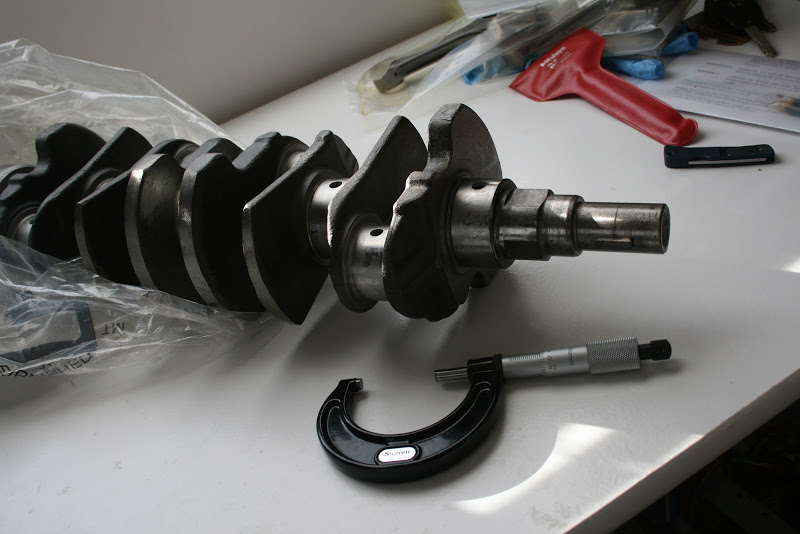
The next day I started into the crankshaft. I measure each crankpin and main a minimum of 9 times.
I'd had it polished locally, and they took off a little more material than I'd have liked. Everything is just bearly under minimum spec. Luckily my rods are on the bottom end of Toyota's specs, so my rod bearing clearances are fine. Will have to wait on the mains.
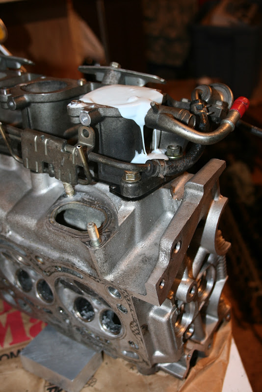
After I was done with the office work I took the AE111 block out to the driveway to give it ithe TechnoSquare treatment.
All of the casting flash and all of the rough parts of the casting in the crankcase was ground down. I then took it to the machine shop to sit in the sonic tank over the weekend. I ordered my rod bearings from Toyota; two sets of #1s and 2 sets of #2s. I have a set of each in the bearing bank in case I need to switch them around. I did take a quick detour through the sales department and test drove an FR-S. I liked it. A lot.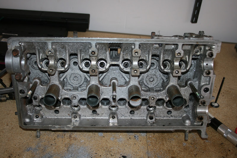
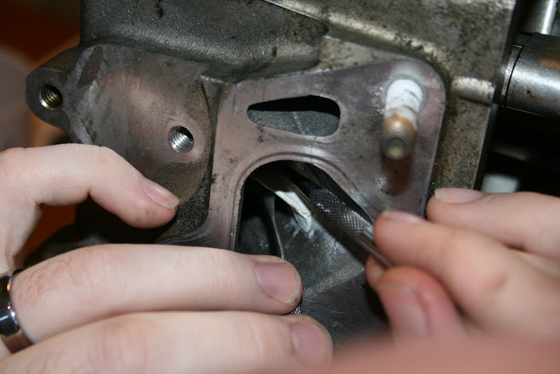
A similar deburring process is done on the head. Unfortunately, while doing bowl work one of my carbides came loose, I think because of a worn bearing in my flex shaft on my die grinder, and ate one of my seats rather deep. New seats on these heads are expensive and many shops are apprehensive about doing them, so I'm looking at a few options. I can probably cut this seat deep and compensate, but I don't think I want to. Equal breathing is important! That woulb mean cutting ALL of my seats deep.
I can also start into the AE111 head that's on the car right now, but I'd like to keep it in running condition. That'd mean switching heads, which would mean putting my AE101 head on it. Not fun.
I also have an AE101 head, but I'm not sure I want to play with it. I have been thinking of epoxying the intake ports and redoing them to be more like AE111 ports, but that's rather involved. Not expensive, though...And the AE101 head I have has good guides and seats.
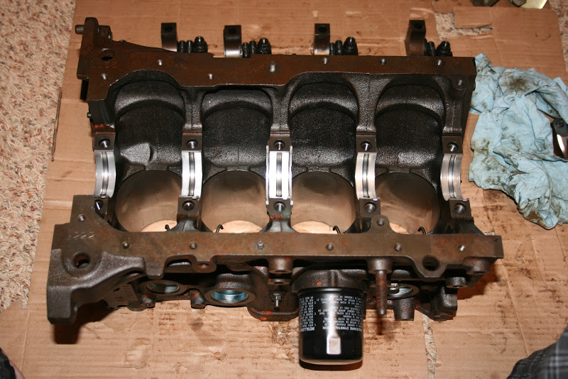
Next I assembled the mains with ARP studs and Tomei ladder bars.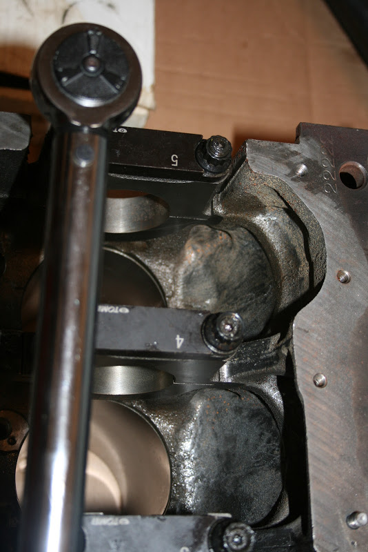
Block didn't come out to shabby. Before I got these all torqued down I realized I missed the washer on the right on main #5. This block is measuring tight and slightly distorted on the mains. I'm picking up a better torque wrench, as I no longer have a Snap-On, and getting my ARP lube from my shop and trying again. If it still isn't right, I've another block at my disposal, but it means more deburring and another weekend in the tank.
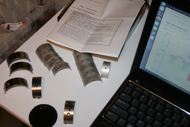
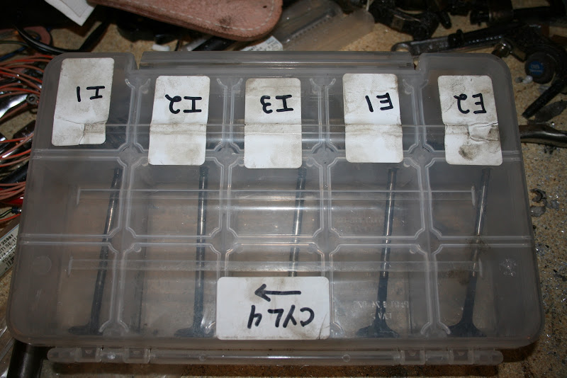
Then I cleaned up some bearings, measured, and labeled them.
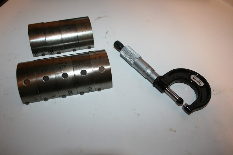
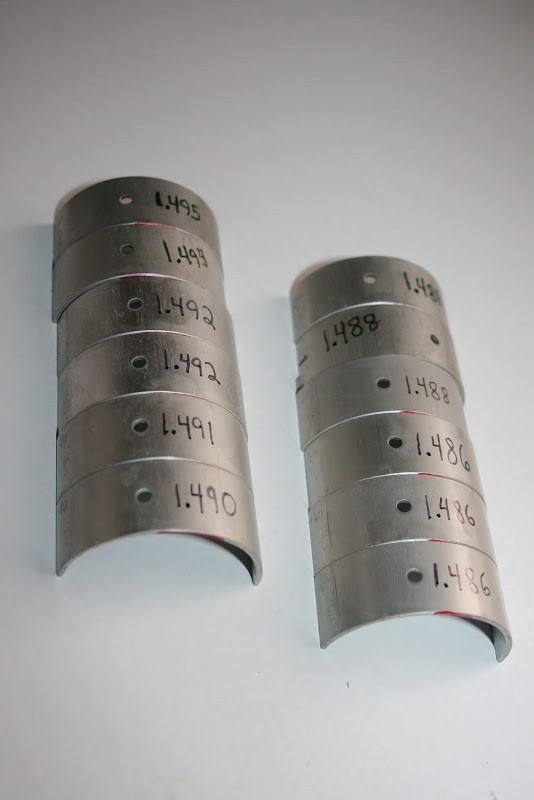
rod bearings came in and got measured out. Not bad.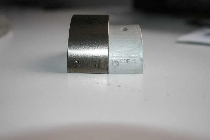
Bearing on the left is a main. Bearing on the right is a rod.
All of the OEM 4A-G main bearings I have are made by TAIHO. 42mm rod bearings are also made by Taiho.
Those 40mm rod bearings, and all 40mm 4A rod bearings I've seen, are marked with that logo. Power Enterprise F1 Black bearings are made by the same company, as are all of the Clevites I've seen for the 4A. I believe it's for DAIDO bearings.
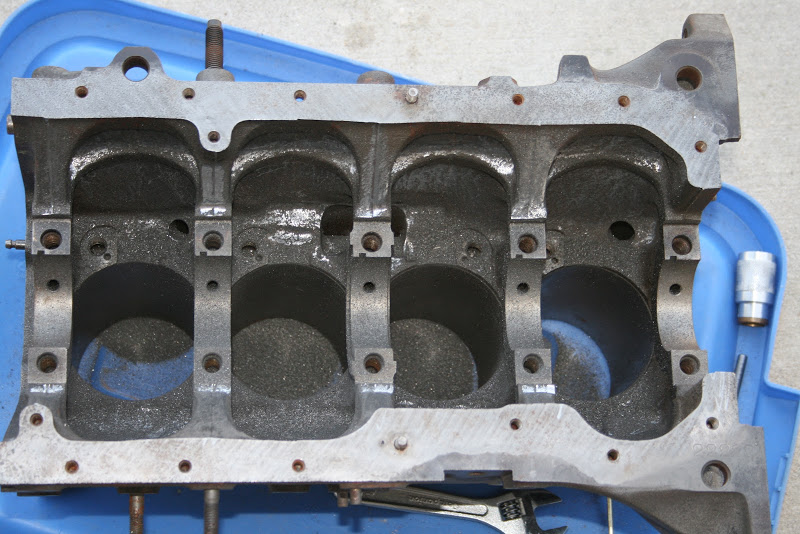
I was not happy with the roundness of the main bores on the block I'd deburred, so I went out to the garage and got another one! This one measured out much better and looked to be a substantially better casting. So much better, in fact, that I'm not going to bother deburring it. Anyway, I measured the main bores, went through my main bearing bank, and put together a set of main bearings.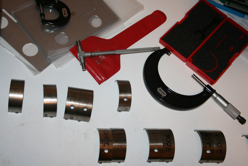
By my calculations, my main bearing clearances are as follows:
1 - 0.029
2 - 0.029
3 - 0.028
4 - 0.029
5 - 0.029
and my rod bearing clearances are 0.041 across the board.
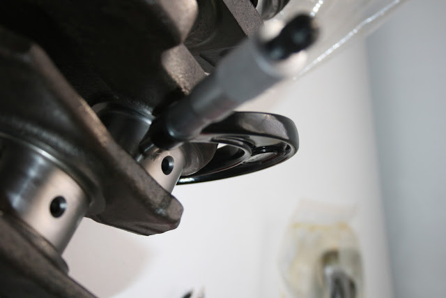
I assembled the bottom end with some Plastigauge.
Here you can see this block is a very clean casting.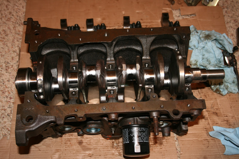
40mm crankshaft. I'm running on the big end of OEM recommended clearances as I plan on revving this thing rather high.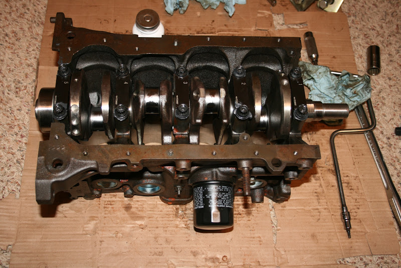
Tomei ladder bars and ARP main studs should help keep this thing together when revving it up there. I'm also going to be using a 7A oil pan, which is a nice aluminum casting and ties into the transmission bellhousing.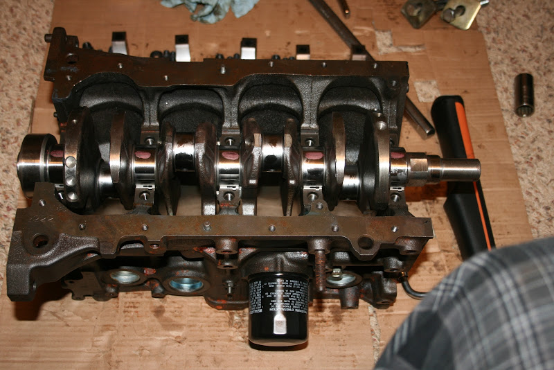
And here's the plastigauge! On the right is my knee. Yes, I'm in my PJs. Again, I'm recovering from something nasty. My wife is an elementary teacher. I call her class 'plague rats'.
Below my knee is my new Brownline torque wrench. It's MASSIVE, which would make it cumbersome in other work, but is fantastic here. The extra length makes it nearly effortless.
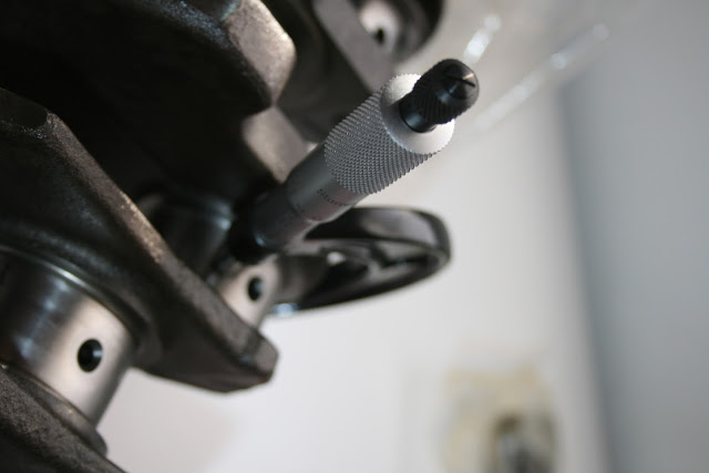
I use a vernier caliper to measure the width of the plastigauge and interpolate between the widths on their card.
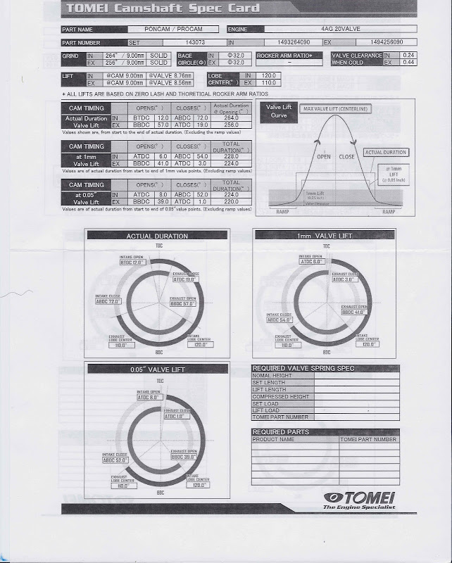
I finally openned up my cams. I got a set of their 20v PonCams for this engine. Tomei has the best timing cards I've ever seen.
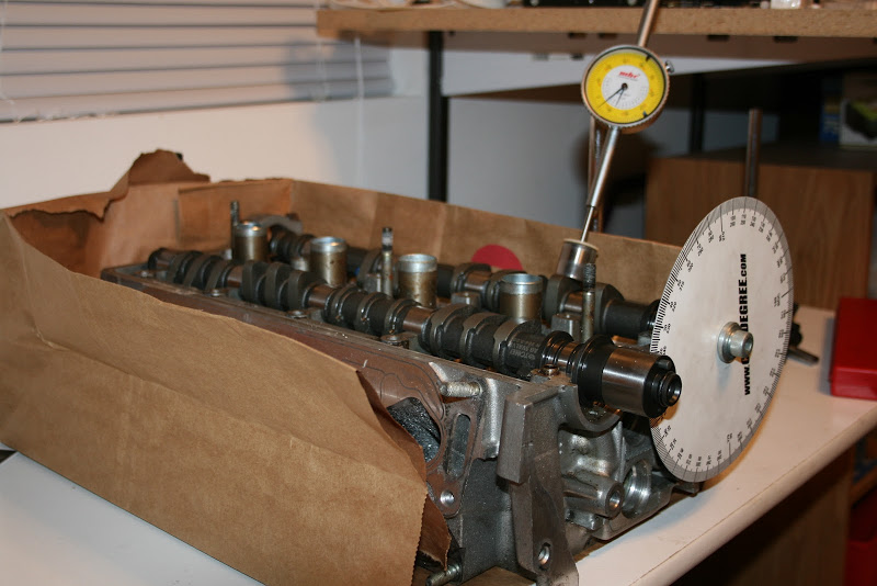
Cams then went into the head to map their profile. I usually have a nice set of V-blocks for this, but these also got left in the FSAE shop at school.
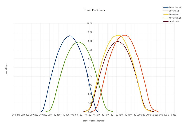
The 16v numbers were from a while ago. I'm not sure if my 16v exhaust timing is right. I'll have to look for a timing card.
That's with VVT changing timing 30 degrees. I'm also not sure if that is right, but I'm thinking it may be considering the advanced timing closely matches the 16v intake timing.
Timing cams is going to be relatively easy for me. I have access to both an AE101 and AE111 intake gear. There's a 5 degree difference in timing between the two. I can also install a Toda offset pin, which provides a further 5 degrees. So I get a choice of four discrete positions for my intake timing, and of course their respective "VVT on" positions. I will likely not screw with the Toda pin unless it would be necessary to get closer to the Tomei centerline.
I have an adjustable exhaust pulley, which may get some fiddling, but I doubt much. The major effect here will be the drastic difference in intake and exhaust manifolds compared to stock, which could produce different ideal timing, but I don't think by much.
As I said earlier, I will probably go to the dyno with an adjustable intake pulley to allow quick intake timing changes. This will allow me to find out which of the two VVT pullies would work better. The order of operations will be:
install AE111 pulley. Find and record centerline.
install AE101 pulley. Find and record centerline.
Extrapolate 2 other centerlines if offset pin is used.
install Toda pulley. Set to whichever timing is furthest from Tomei specs. Record position on pulley.
Set to whichever timing was closest to Tomei specs. Record position on pulley. Calculate VVT positions. Make sure I can actually achieve them within Toda adjustment range. If not, move a tooth on the belt, modify the pulley, etc.
Take it to the dyno! Having the positions known will mean a minimum of fiddling around on the dyno proper. I can quickly adjust between my discrete positions.
I ordered up some port epoxy. I'll be taking a go at modifying AE101 ports to more closely resemble AE111 ports. This should also give me some practice before I go and epoxy on tho FSAE cylinder head. I'll also be talking to a local shop about my AE111 head and we'll see what can be done with replacing the seats.
AE101 head came apart, was cleaned up a little, and set up for molding!
When you're playing with valvetrains, you better keep your stuff in order
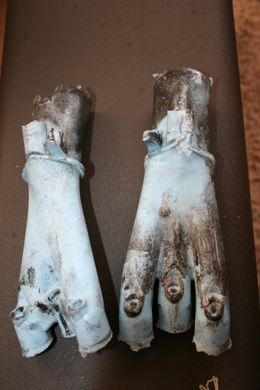
Next, cast the ports in anarobic silicone RTV.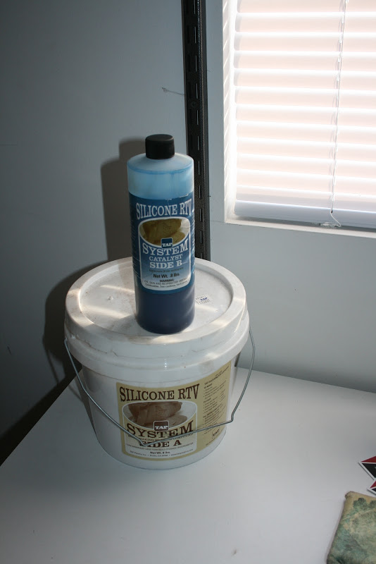
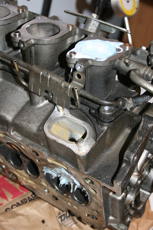
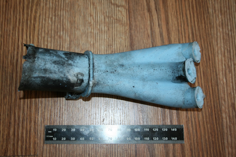
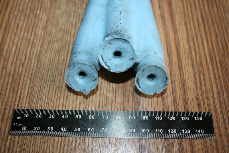
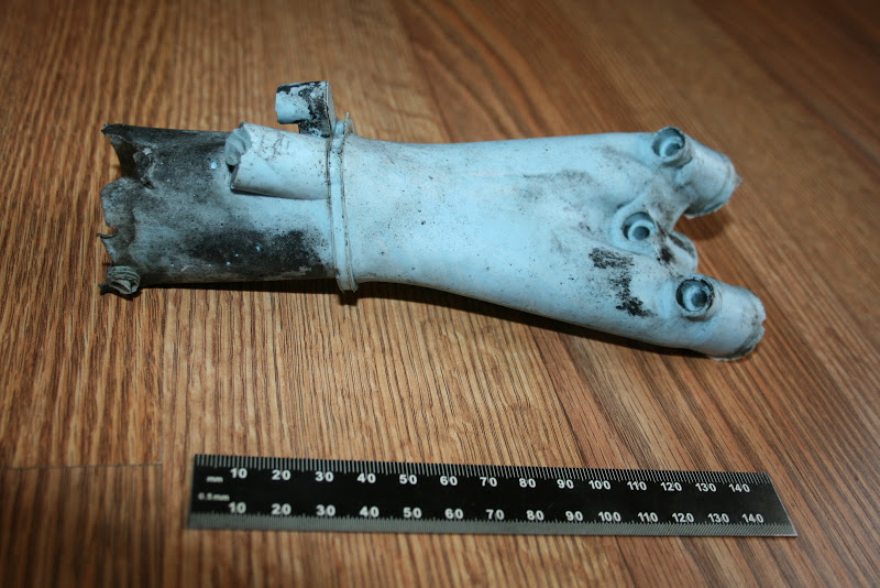
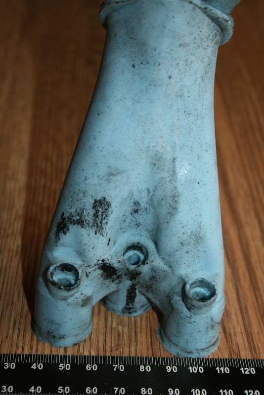
I included the intake manifold to illustrate the discontinuity between the intake angle and the port angle. It is easy to imagine Yamaha/Toyota was compromising in packaging the injection.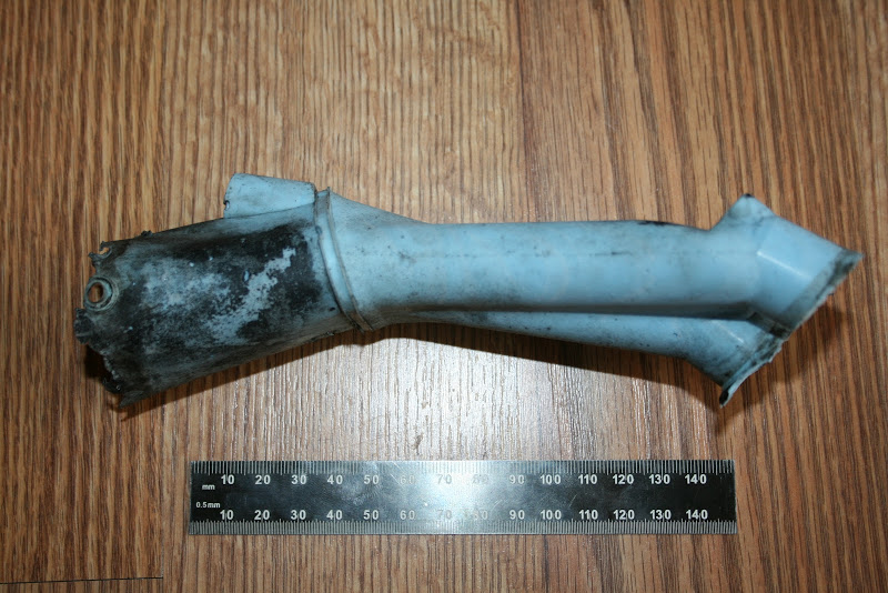
It's hard to tell, but this is an AE111 head. So we will have molds of both 20v heads!
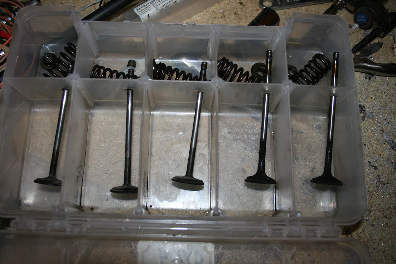
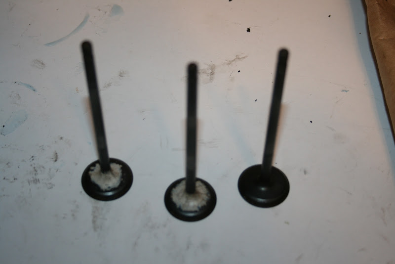
I found the valves I'd used for doing valve testing. The numbers I came up with as being most ideal are VERY similar to the valves Ferrea later developed, which is why a set is sitting here ready to go on whatever head I end up using.
I've installed the Ferrea valves in the AE101 head and got it ready for the flowbench. Unfortunately my shop laptop and USB > RS232 adapter is, you guessed it, at the FSAE shop. I'll have to either wait or order another if I'm going to get this head flowed!
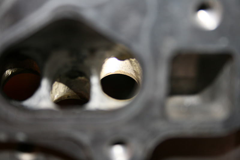
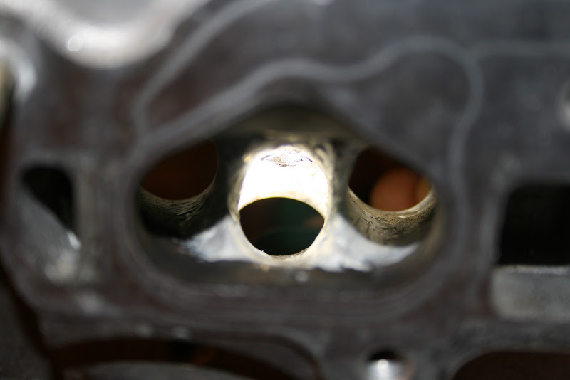
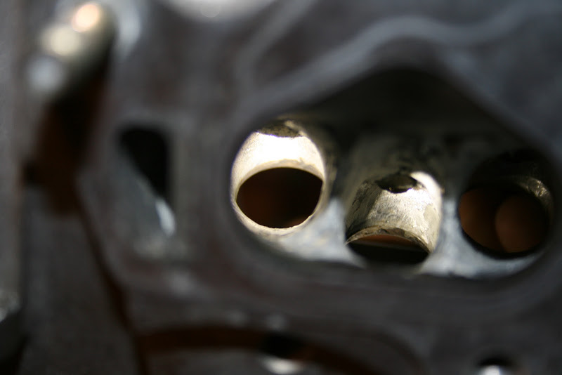
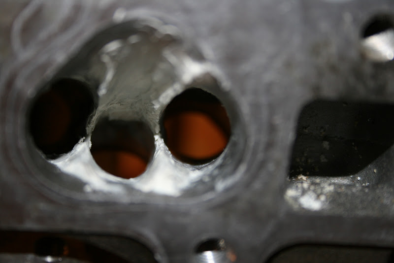
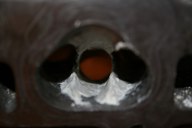
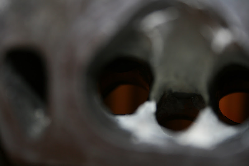
Aaaaand here's the difference between AE101 and AE111 intake ports!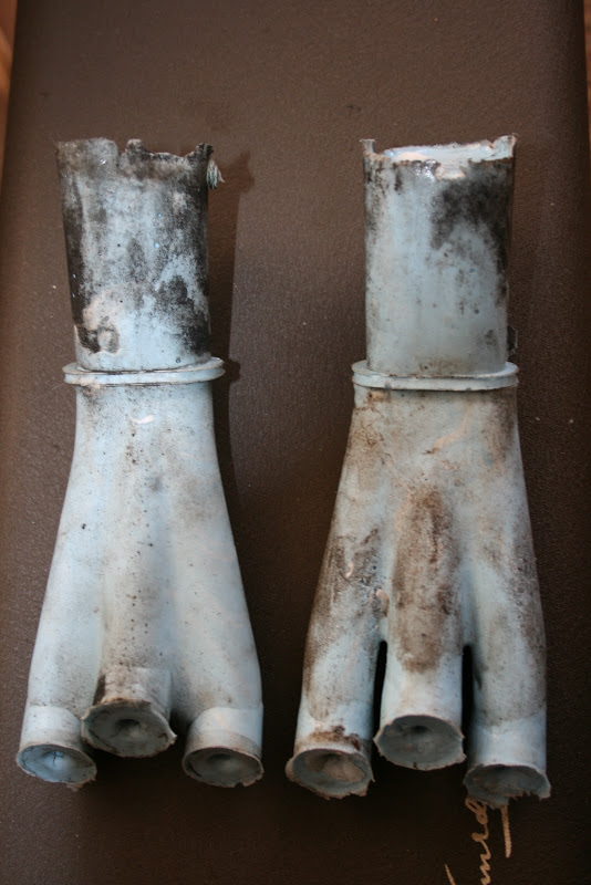
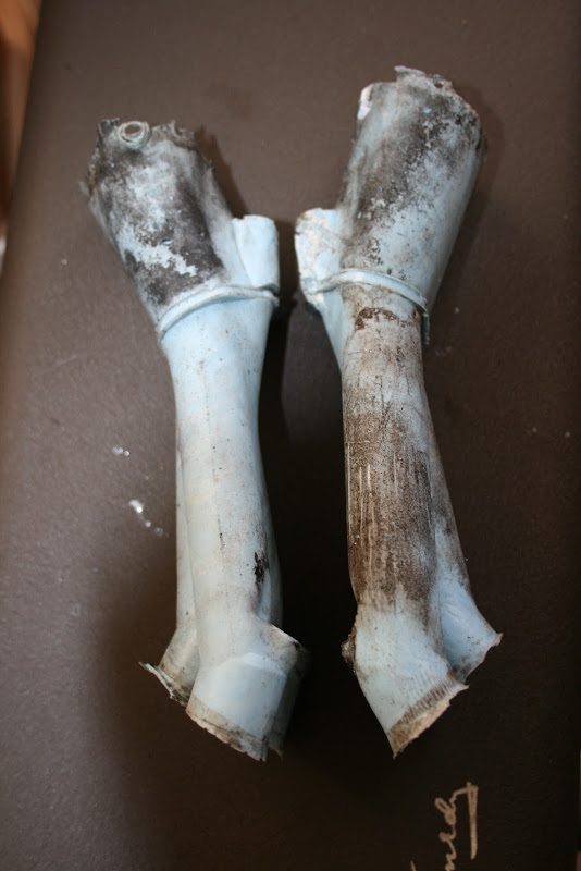
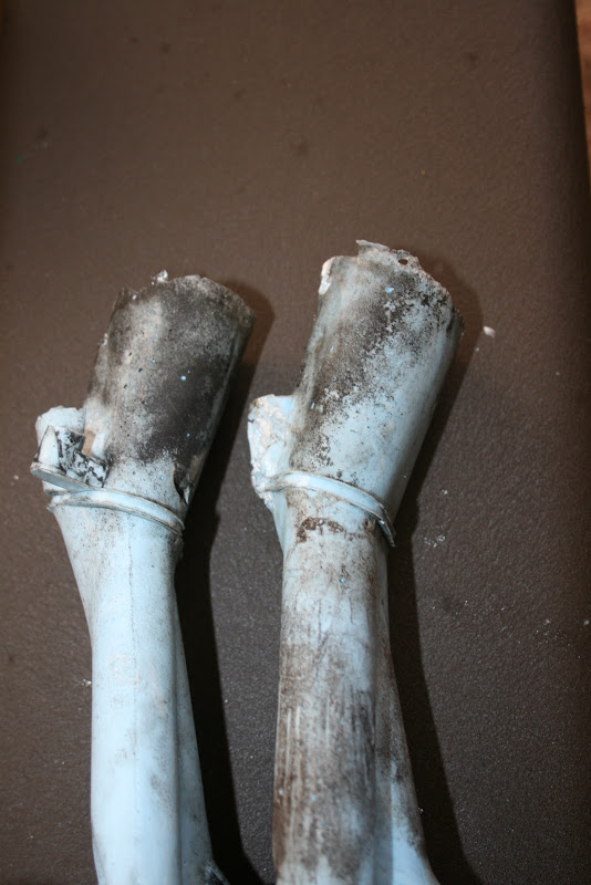
There is enough of a difference between the side walls of the ports that I wonder if duplicating an AE111 port on the AE101 head will be possible without running into other cavities in the head.
I spent time today with plasticine, shaping tools, and an untouched silvertop head. I'm starting with an untouched port. Next I'll open up a different port on the head and make changes such as the desperately needed short-side-radius, bowl, and valve-guide boss work. I'll then build up that port with plasticine and see what I can do.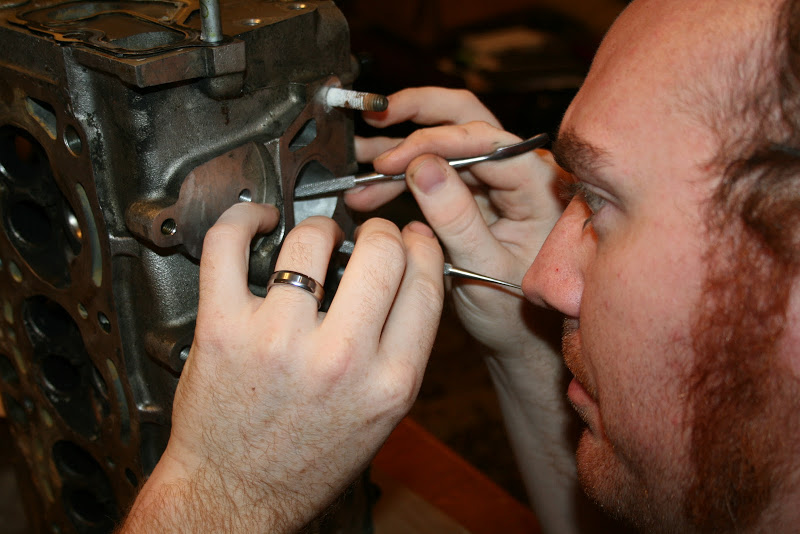
Here's where we are at now:
Not done yet, but getting there.
Thank you very much!
I took some time and started into a blacktop head as well.
This one isn't as far along. You can see it's not quite symmetric yet, but that's the beauty of doing this with plasticine first. As of right now I'm happier with how the blacktop port looks than the silvertop. It was easier to get this far with it. We'll see how it flows.
I need to find a macro lense for these, or better lighting. Or both.