- 10" SeeLite SR Light Bar (incl. mounting hardware)
- (2) 1.5" Bolts
- (6) Washers
- (6) Neoprene Rubber Washers
- (2) Lock Washers
- (2) Flange Nuts
- (1) NTE 54-225w SPST On-Off Rocker Switch
- (1) Deutsch DT06-2s Plug Connector
- (2) 1/4" Quick-Connect Terminals
- (2) 1/4" Ring Terminals
- (1) Inline Fuse lead
- (1) 5A Fuse
- Approx. 20' 16 awg wire
- Heat Shrink Tubing
- Butt connectors
- Dremel (or equivalent)
- Bastard file
- Small files
- Fine tooth hacksaw blade
- Wire strippers and crimpers
- Tape measure
- Painter's tape
- Electrical Tape
- Small & large flat-head screwdrivers
- Center punch
- Sharpie
- Soldering iron (optional)
- 10 & 12mm wrenches
- 10mm socket and driver
- LIGHT!!!
- 6-pack of your favorite frosty beverage
You must be logged in to rate content!
15 minute read
SeeLite Light Bar Install/Review *PICS*
Compliments of Benson X @ www.tacomaworld.com
8-5-2013
*Just a heads-up - If you haven't seen my write-ups before, they tend to be long, very detailed, and there are a lot of words. Comments, PMs, questions, and criticism are welcomed; stupid remarks like TMWDR or TL;DR will be responded to with another stupid acronym - GTFO! I take no responsibility for any damage or injury from anyone attempting this mod. Do so at your own risk. *
Here's a little bit about SeeLite:
SeeLite specializes in custom LED lighting, with their primary focus on hunting and fishing boats: bow-fishing, night-fishing, duck lighting, warm lighting, trouble lighting etc. After talking with Josh, and seeing their FB page, it was obvious that they are dedicated to their craft and have done some impressive builds that really show they take pride int what they do. They have garnered some good praise, and have created quite the following in their regional fishing and hunting community; along with sponsoring some big names with their custom-outfitted applications.
They want to further increase their footprint in the off-road community as well, and Josh is a fellow Toyota enthusiast / modder. Knowing how competitive the LED industry is right now, he's doing a great job and I hope that he succeeds. I also hope that he can put together a special offer or Group-Buy for TW.
On to the Write-Up!!!
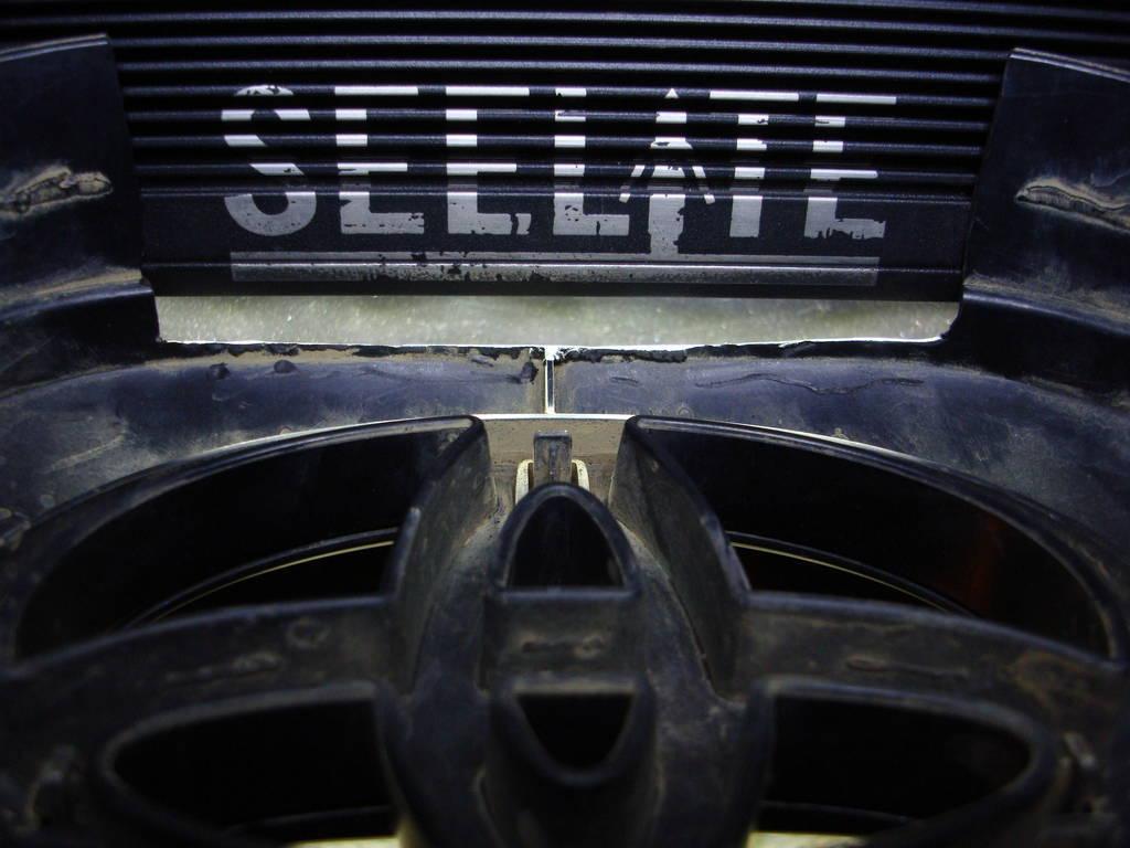
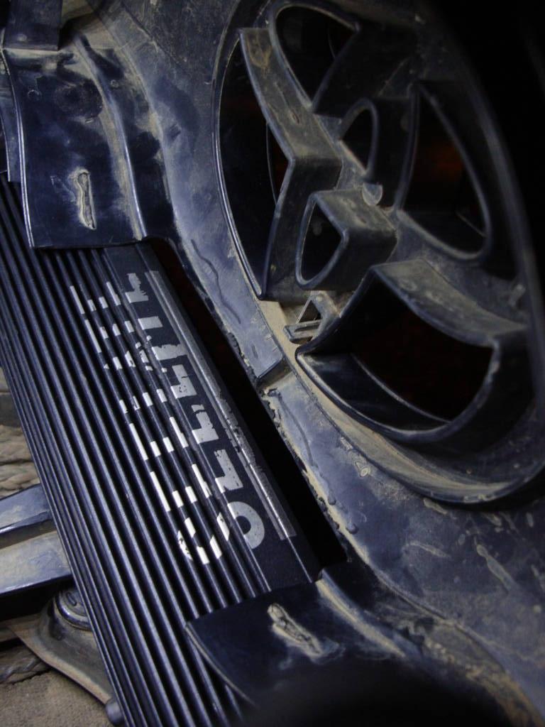
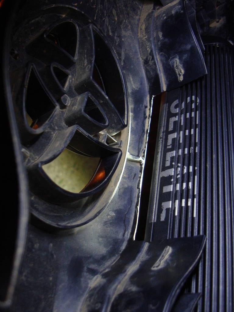
The light-bar itself seems to be well-constructed and pretty much idiot-proof. The model I got is this one, customized with the SeeLite logo stenciled on the top:
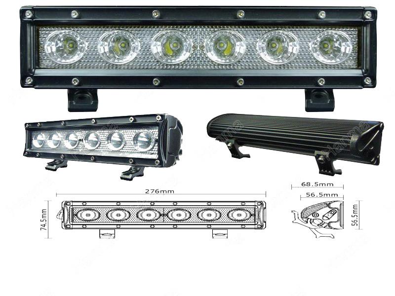
Here are some specs.
. LED Power: 30W
. Operating Voltage: 10-30 vDC
. Waterproof rating: IP 67
. (6) 5W High Intensity CREE LEDS
. Current draw:12V 2.40A,24V 1.12A
. Color Temperature: 6000K
. Material: Die-cast aluminum housing
. Lens material![]() C
C
. Mounting Bracket:zinc alloy
. Beam: Flood Spot Beam
. 30000 hours above life time
. Dimensions:10.5 inch
. Certificates:CE, RoHs, IP67
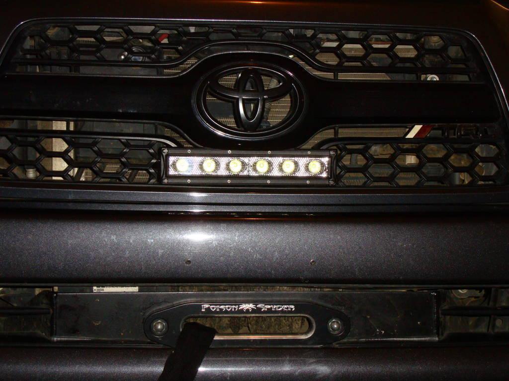
I had an idea months ago (prior to Rigid's design ![]() ) to mount a 10"SR in my grille, underneath the Toyota emblem. I had taken some measurements, and knew that it was possible. I also saw rkfoote's write-up on how to mount a similar 10" light-bar in the hood skewp, which also had me intrigued. After getting the dimensions, I realized the SeeLite light-bar would be too tall to mount in the scoop, so I planned to install it in the grille. The light-bar I received did not include a wiring harness (sold separately), but I easily made my own.
) to mount a 10"SR in my grille, underneath the Toyota emblem. I had taken some measurements, and knew that it was possible. I also saw rkfoote's write-up on how to mount a similar 10" light-bar in the hood skewp, which also had me intrigued. After getting the dimensions, I realized the SeeLite light-bar would be too tall to mount in the scoop, so I planned to install it in the grille. The light-bar I received did not include a wiring harness (sold separately), but I easily made my own.
PARTS USED:
10" SeeLite SR Light Bar (incl. mounting hardware)
(2) 1.5" Bolts
(6) Washers
(6) Neoprene Rubber Washers
(2) Lock Washers
(2) Flange Nuts
(1) NTE 54-225w SPST On-Off Rocker Switch
(1) Deutsch DT06-2s Plug Connector
(2) 1/4" Quick-Connect Terminals
(2) 1/4" Ring Terminals
(1) Inline Fuse lead
(1) 5A Fuse
Approx. 20' 16 awg wire
Heat Shrink Tubing
Butt connectors
TOOLS USED:
Dremel (or equivalent)
Bastard file
Small files
Fine tooth hacksaw blade
Wire strippers and crimpers
Tape measure
Painter's tape
Electrical Tape
Small & large flat-head screwdrivers
Center punch
Sharpie
Soldering iron (optional)
10 & 12mm wrenches
10mm socket and driver
LIGHT!!!
6-pack of your favorite frosty beverage
Step 1: Cutting & Mounting
The first thing I did when I got the light-bar was connect it to the switch for a test-run. Everything worked as it should, and I let it run it for 1-hour to make sure it wouldn't radiate too much heat. It got warm to the touch, but not hot enough to melt the plastic on my grille.
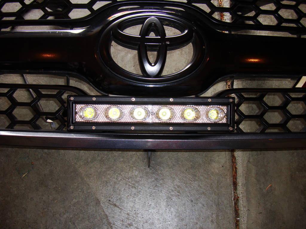
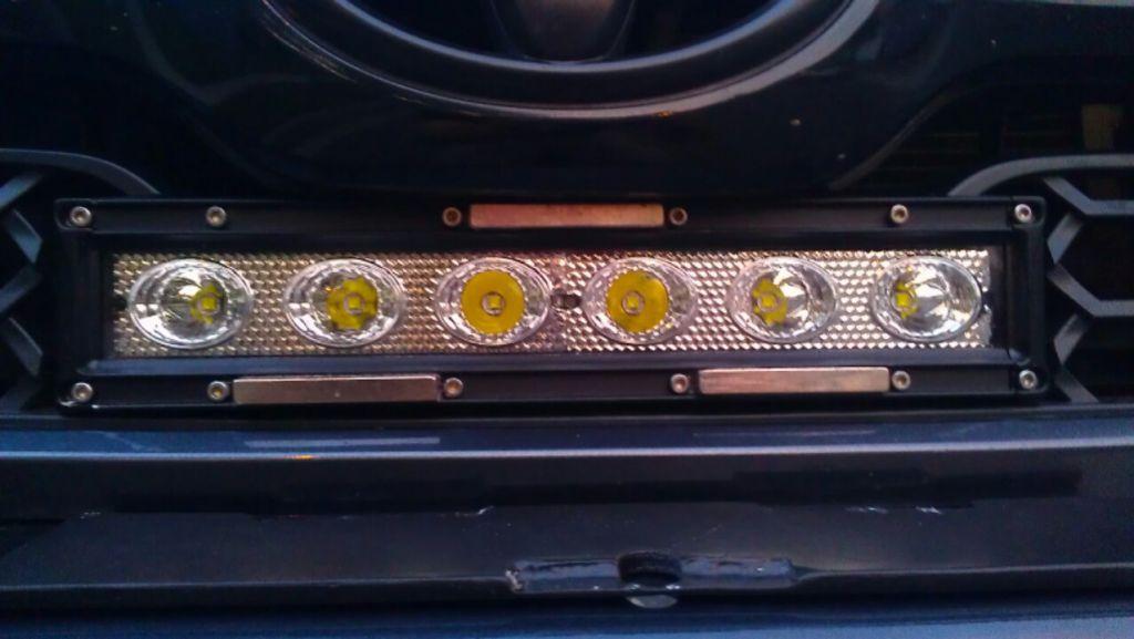
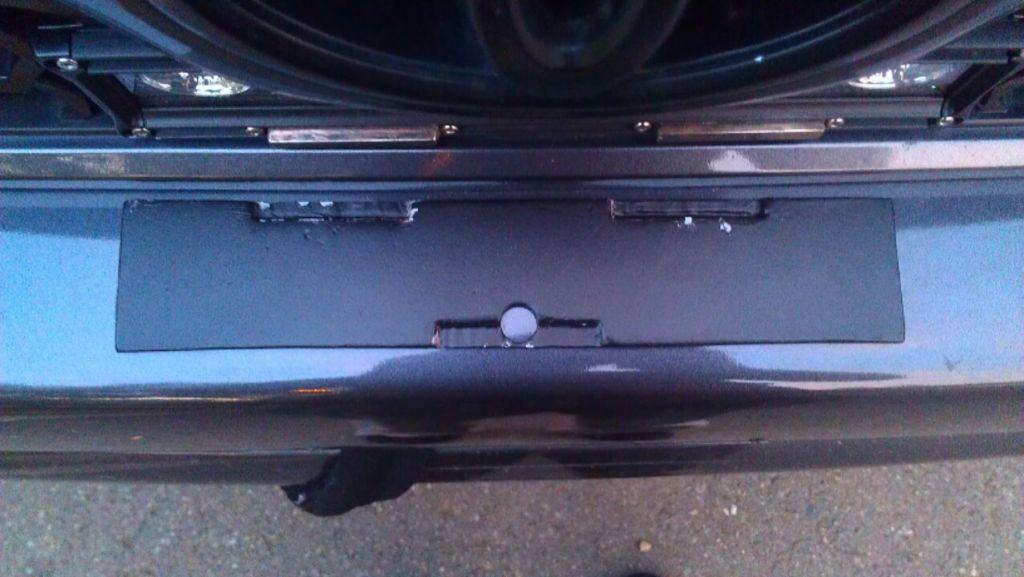
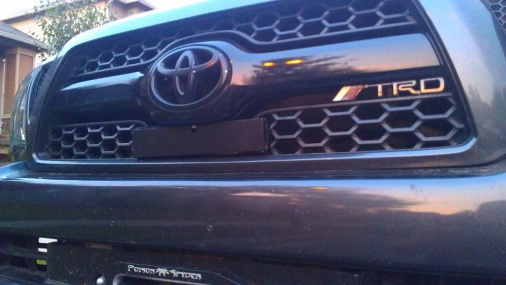
Next I proceeded to cut the shit out of my grille. I measured the length of the light-bar, and when centered under the Toyota emblem, it lined up almost perfectly with the honeycomb edges on the '11 grilles. I masked each cut-line with painter's tape, and used the hacksaw blade to cut out a rectangle shape for the light-bar. I also had to trim upwards, in order to leave the plastic lip on the bottom of the grille in-tact, since that was my mounting/fastening area. I had to do A LOT of minor trimming and filing on each side and above to make it fit. I didn't take pictures of the process, and it turned out great for what it is, but not as perfect as I'd like it to be.
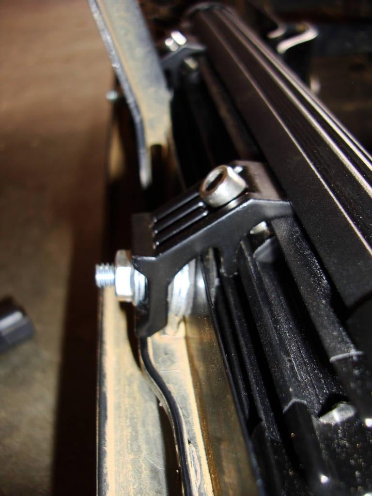
Once I persuaded the light-bar to fit snugly, I had to figure out how to mount it. The hardware that was included was awesome, and I regret not taking pictures of it prior to the install.
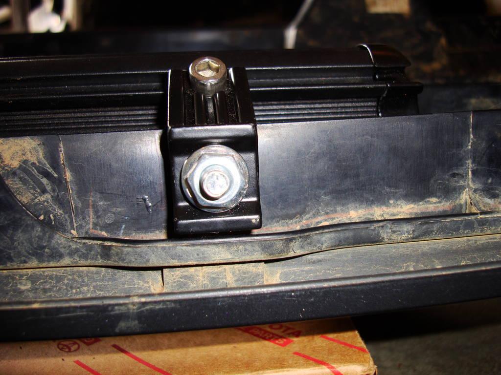
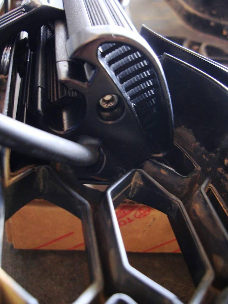
The mounting kit consisted of (2) oval-shaped nuts that slide into a channel on the back of the light-bar. (2) mounting feet fit into the back of the light bar, and bolt into the "slide-nuts" with supplied allen-head bolts and allen wrench. The feet mount to a flat surface with (2) supplied allen-head bolts, but these were too tall for my chosen area, so I substituted some 1.5" 1/4 bolts instead.
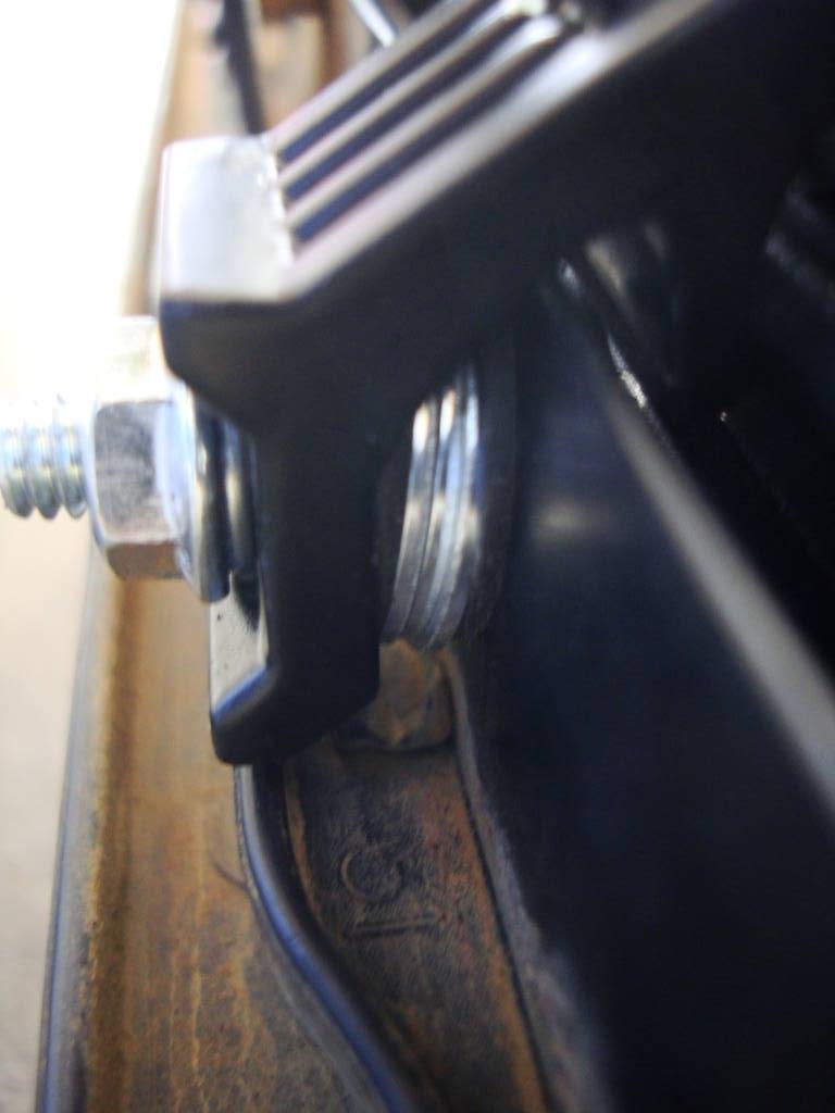
I had to get creative with the mounting, since the feet barely fit, and left a large gap for me to fill. I used my center-punch to mark my holes, and Dremeled 2 holes in the bottom plastic lip on the grille.
I had to use washers and neoprene washers on each side to fill the gap and to make sure it wouldn't crack the plastic I was bolting to.
Step 2: Wiring !Disconnect the battery!
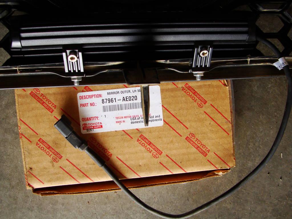
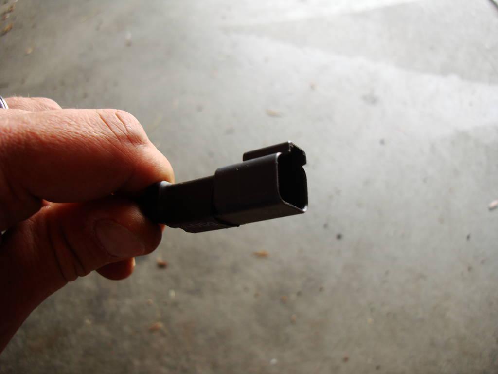
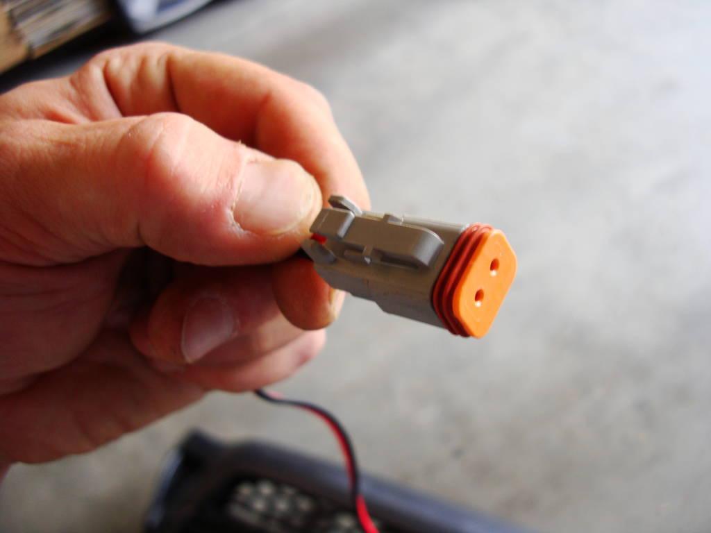
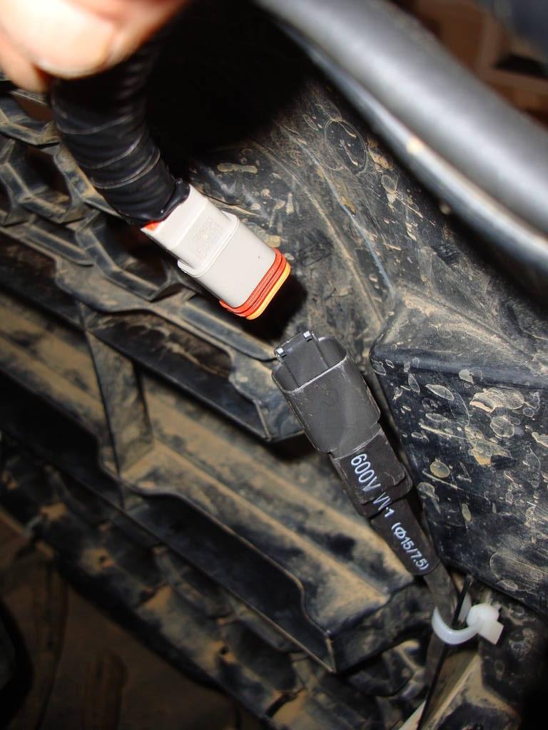
The light-bar had about a 14" lead with a specialized plug on the end of it. Since it didn't include a wiring harness, and I didn't want to drop $30+ on one, I had to build one myself. I am not an electronic guru, so I had not idea what type of plug it was, but after searching around for a bit I found it was a standard Deutsch 2-pin plug. I ordered one for $3 on eBay.
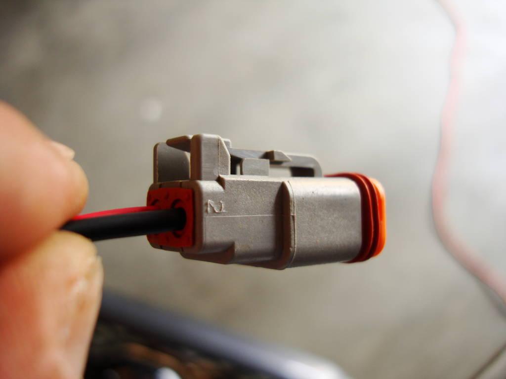
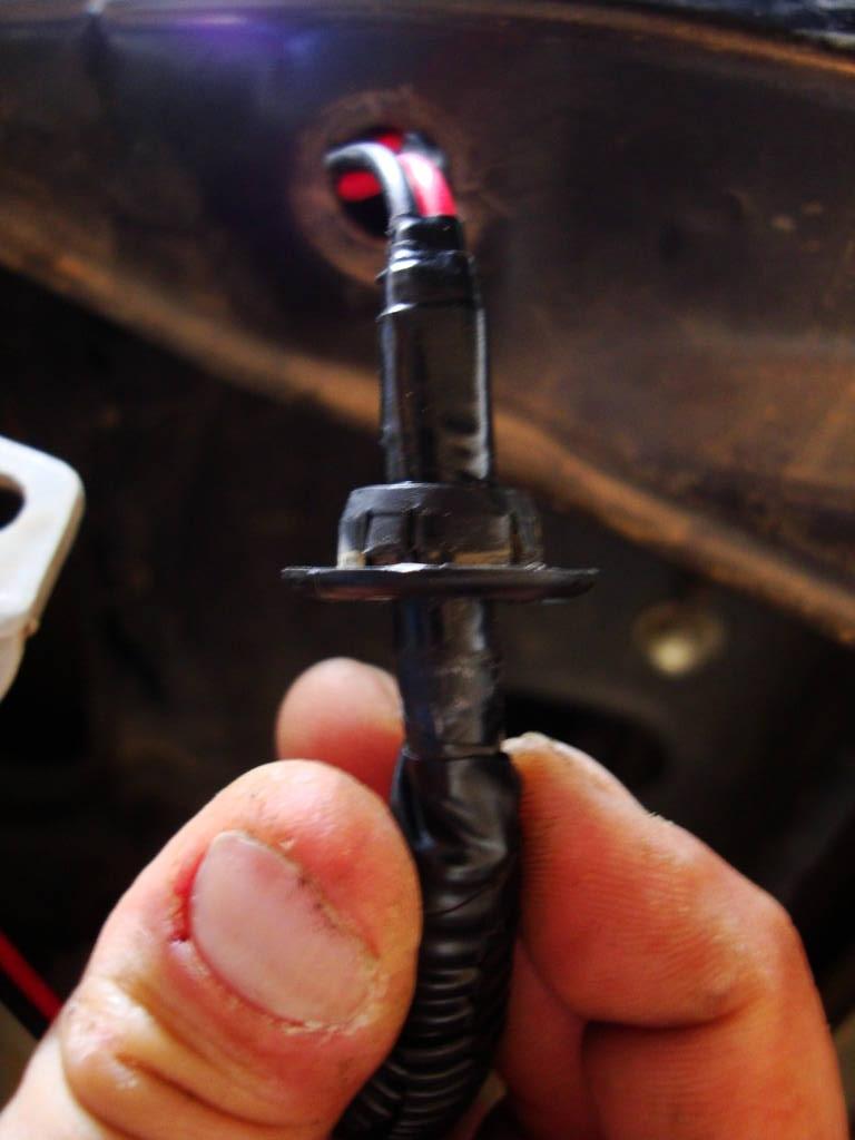
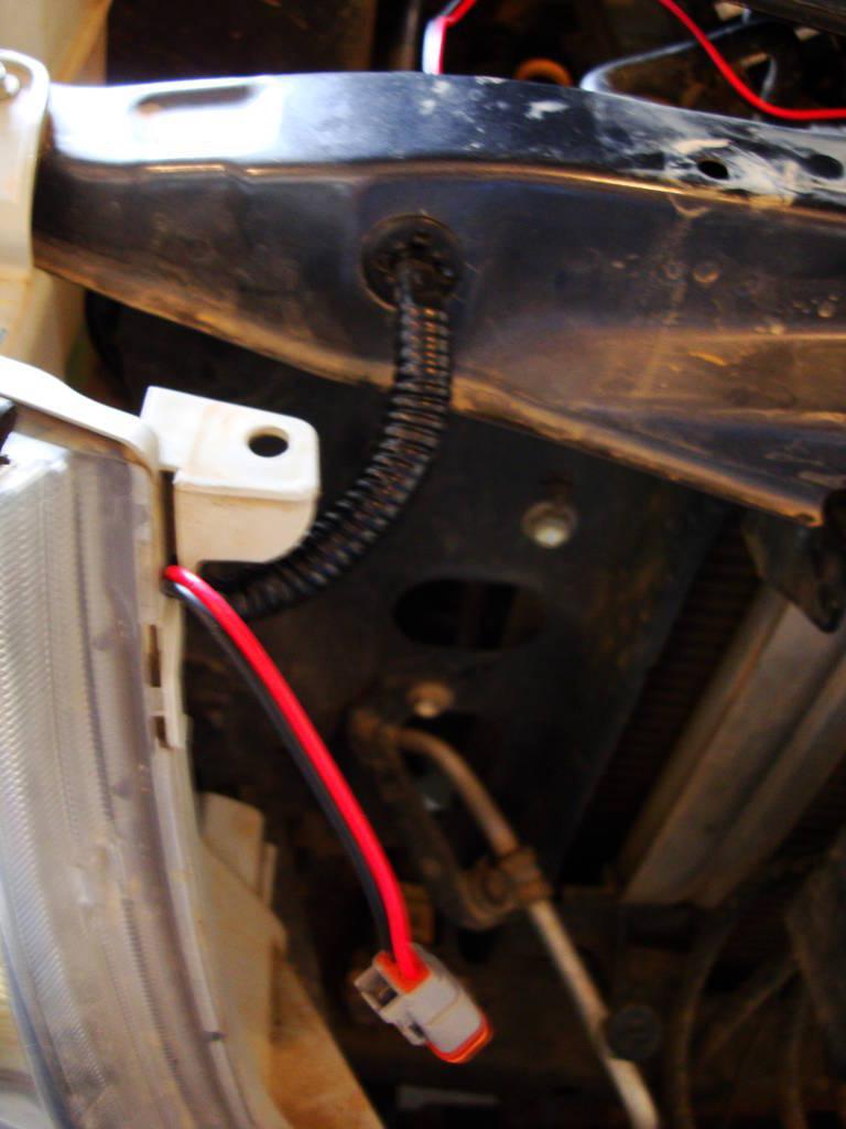
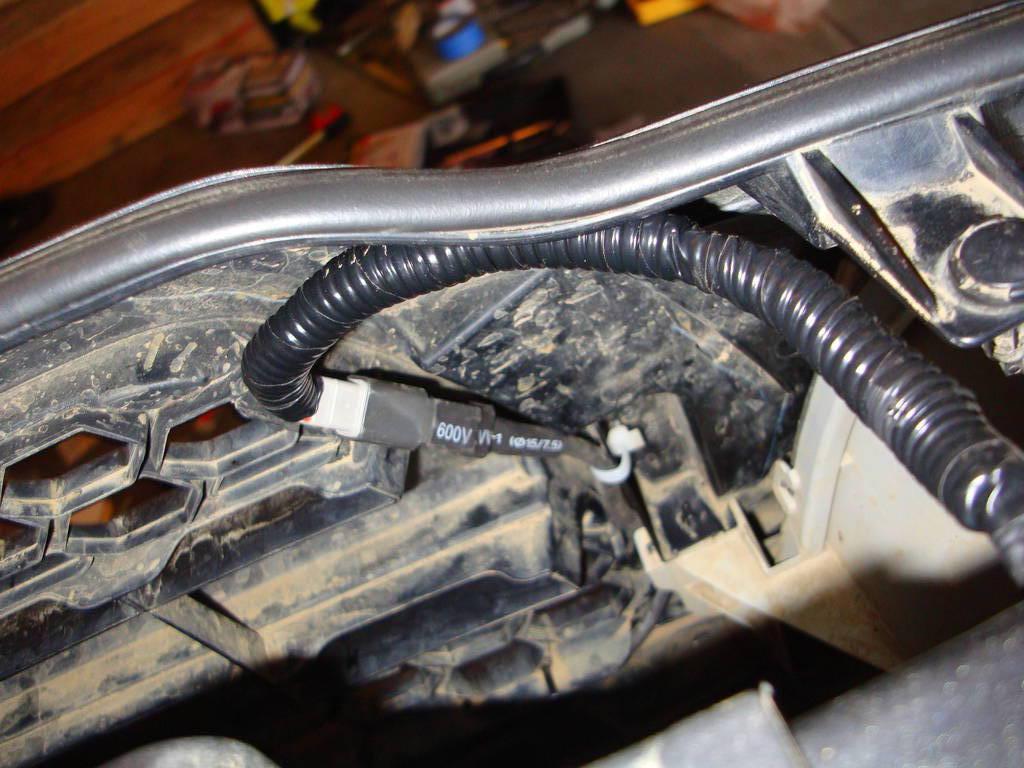
I ran a length of POS and NEG wire from the Deutsch plug to the battery, and clipped them off. Since I have the Redline hood struts, I decided to make use off my old hood-prop retainer clip, and ran my wire leads through it, and underneath the radiator support. I reinforced both sides of the lead with electrical tape, so it couldn't get tugged in or out of the hole. Then I wrapped the end in plastic conduit and electrical tape.
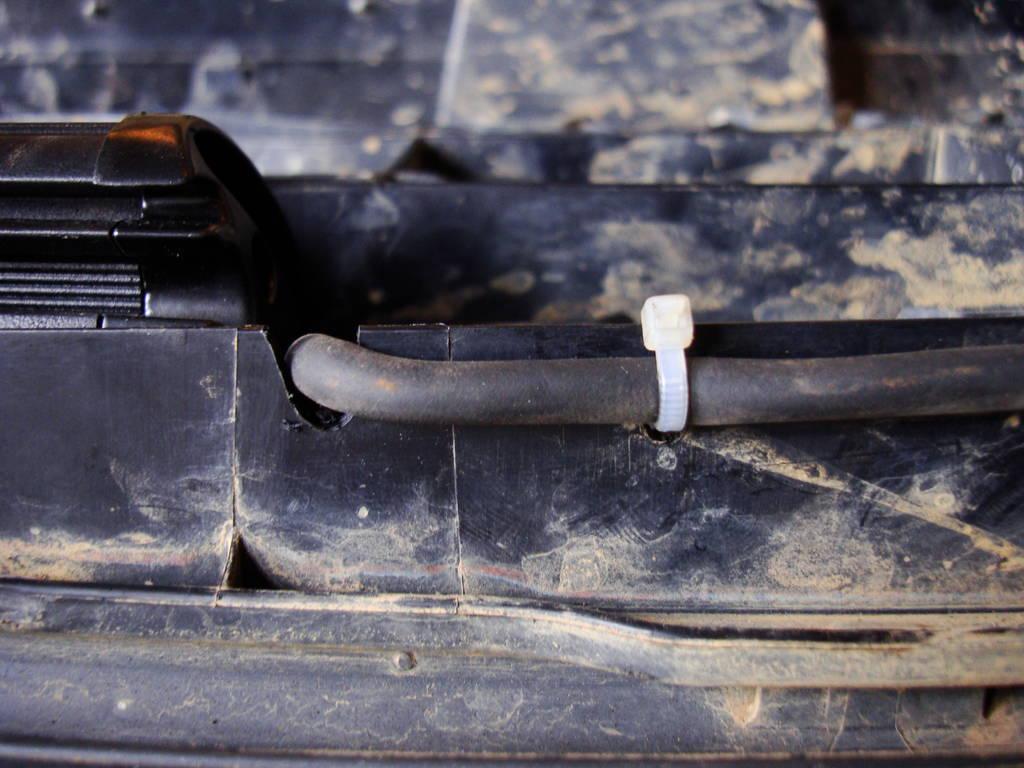
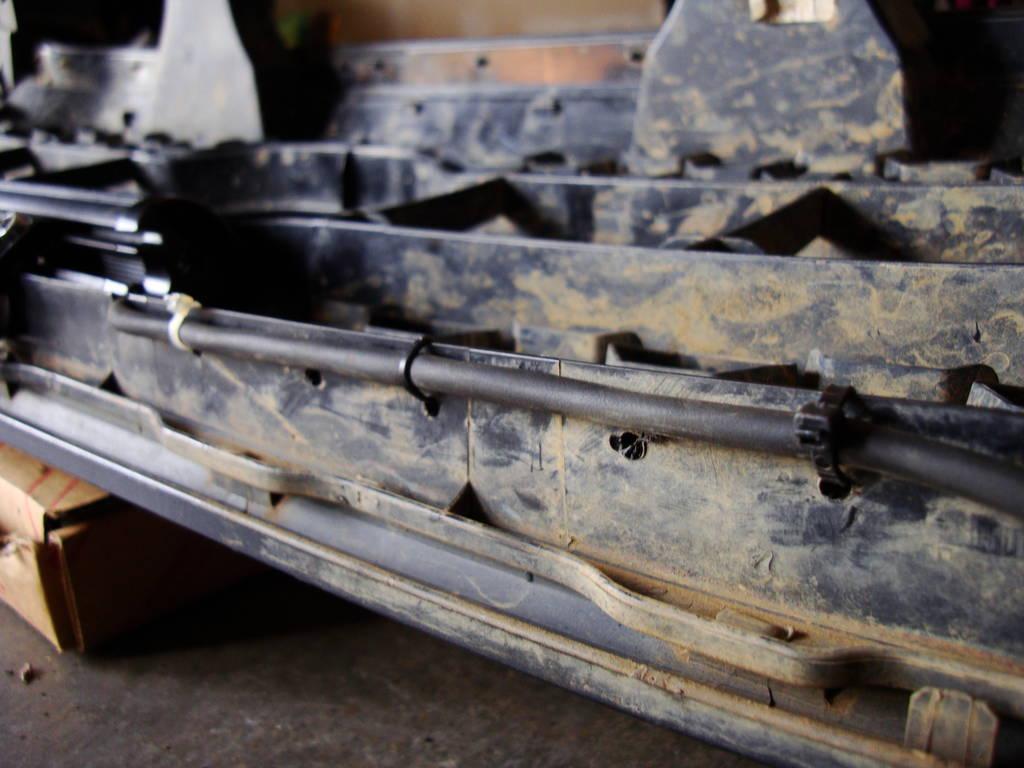
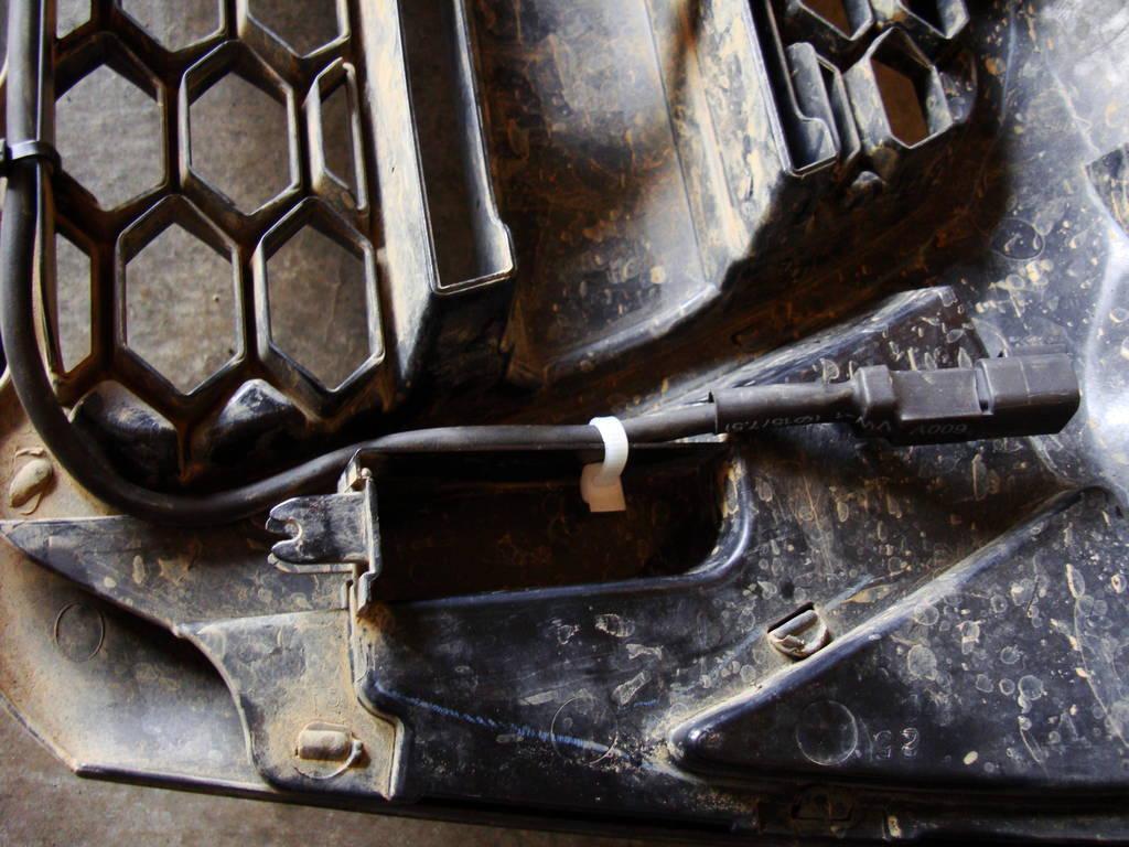
Then I zip-tied the light-bar lead to the grille itself. I Dremeled out a notch for the cable to fit in, and drilled some holes along the bottom and side, to secure it with zip-ties.
After the Deutsch plugs were wired and ready to go, I moved into the cab to start wiring in the switch.
I was very minimalistic with the switch. I was originally going to get a fancy OTRATTW switch and add a relay and all that jazz - but after thinking about it, I chose the easiest and most-basic circuit with the least amount of wiring.
The light-bar only draws 2.5 amps so there was no need for a relay. I wanted to have it on-demand anytime, so a fused direct-power source made sense, and eliminated the need for an ignition powered tie-in. I didn't need an illuminated switch, since I would sure as hell know if the light was ON or OFF, so that cut down on the wiring as well, and also the need to potentially connect to a dimmer source.
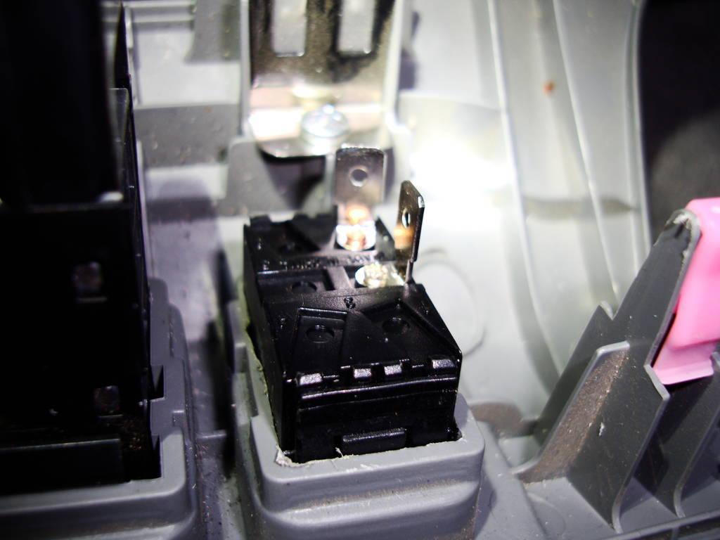
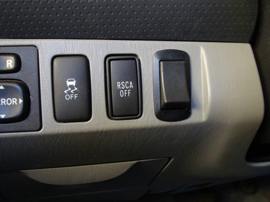
I went to my favorite local electronics store, and found a simple SPST On-Off rocker switch (NTE 54-225w) that would fit perfectly in the last "switch blank" I had left (with some trimming of course).
I pushed a doubled-over length of wire through the firewall grommet (always a fun task ![]() ) and terminated each end with a 1/4" Quick Connect terminal. I heat-shrinked the terminals, and secured them to nearby wiring-harnesses with zip-ties and connected them to the switch.
) and terminated each end with a 1/4" Quick Connect terminal. I heat-shrinked the terminals, and secured them to nearby wiring-harnesses with zip-ties and connected them to the switch.
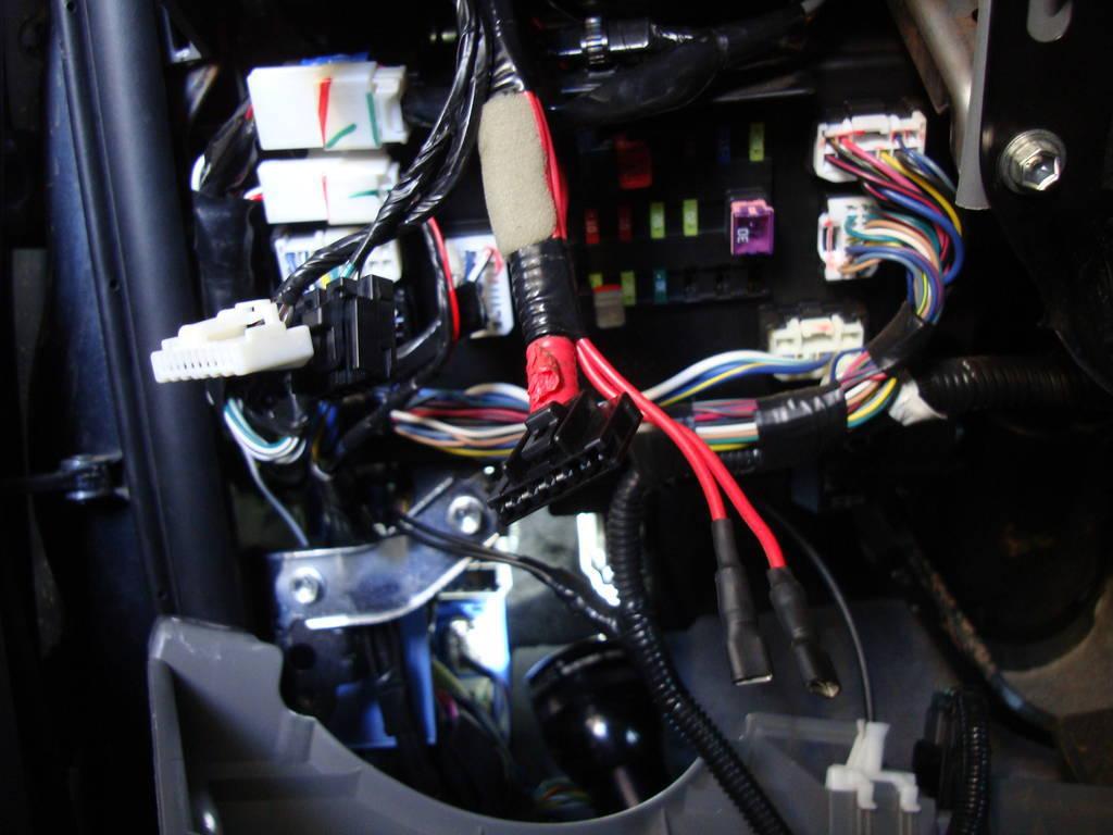
All that was left was to connect the switch to the battery and the light bar, and add a ground connection. I crimped on a 1/4 ring terminal to my 5-Amp inline fuse, and connected it to the switch lead. I then connected the second switch lead to the POS lead from the light-bar. I crimped on another 1/4" ring terminal to the NEG lead from the light-bar, and connected it to the battery's ground point.
I tucked everything up using more zip-ties and re-connected the battery.
Ahhh!!! Let there be light and have a beer while basking in the basking in the 3000 lumens of bright-ass white light!
Step 3: Testing
This isn't a 50" light-bar or a Rigid SR-Combo, and it isn't trying to be. It's a modest 10" light-bar with (6) LEDs. Based on that, some would think I invested too much time/effort into making it work how I did - but that's what I wanted to do, and don't regret it at all. I am seriously impressed with the light-output from this little guy.
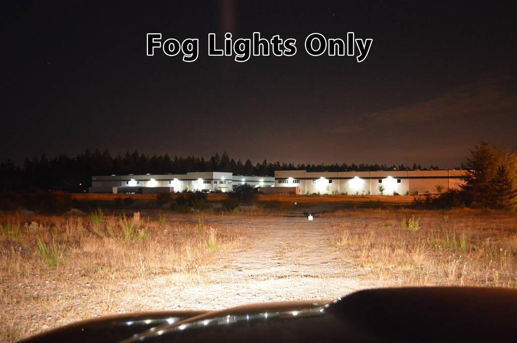
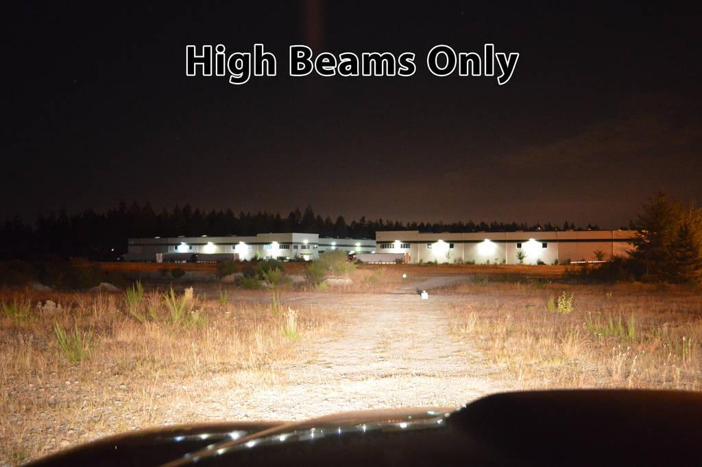
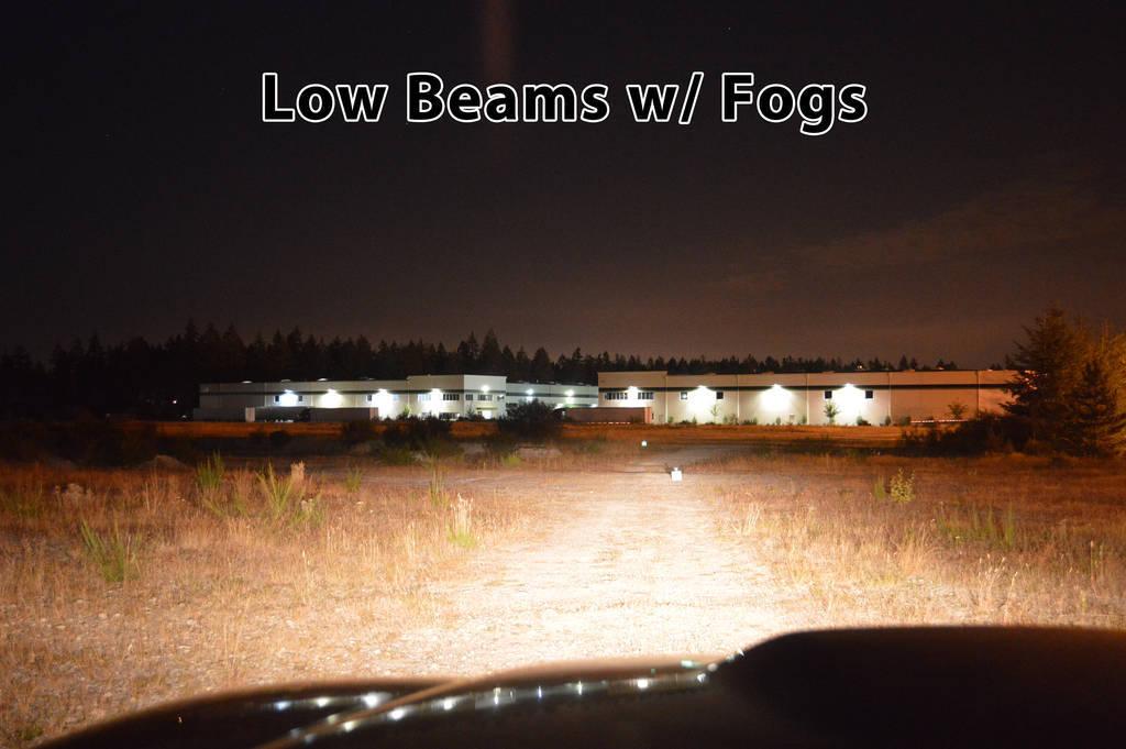
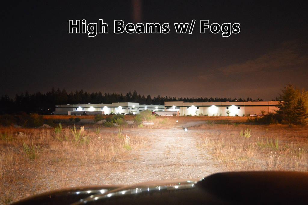
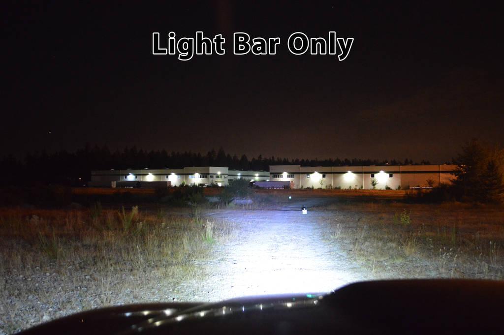
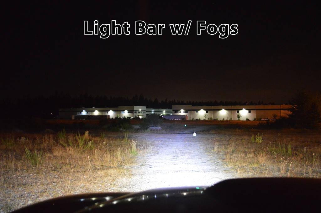
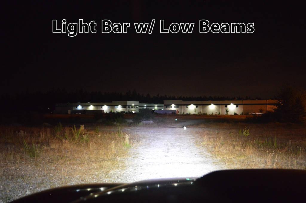
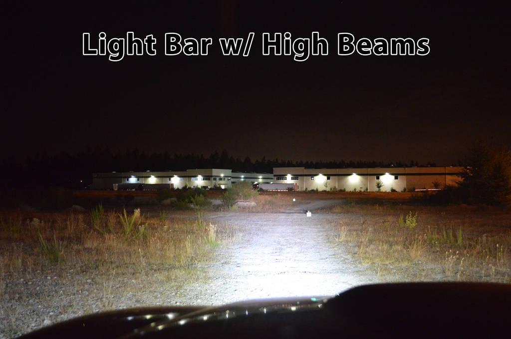
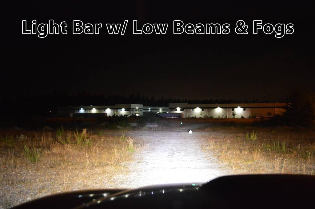
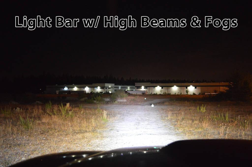
I took the following series of photos in succession, in an attempt to show all the different variances and light-outputs of the different combinations of fogs, lows, high, and the light-bar.
I placed reflective targets at 2 different distances away from my truck. You can also see the reflective tape on a semi over 1000ft. away, and another road sign in the distance.
Target #1 = 175ft. away
Target #2 = 350ft. away

Step 4: Summary
When I was retrieving my targets, I left only the light-bar on and it completely illuminated the area (even @ 350ft.) as if I had a flashlight with me. I was pretty impressed by that.
I think this thing puts out an impressive amount of light for the size, especially when combined with the other lights. It will be extremely useful when offroading, and should illuminate the area directly in front of the winch nicely. It will also increase my truck's visibility in the event I am on a mission for SAR, thus making it easier for the subject to spot me.
I want to make a cover for, so I ordered a few 2"x1/8"x1/8" Neodymium magnets that "should" fit in the channels of the light-bar's face perfectly. I plan to epoxy (or something) them in each channel, and make a mating metal cover to pop-on the front. The magnets have a 7.4lb pull each, so with 4-6 of them, it should be strong enough to securely hold a piece of metal on there. I may route some recessed "pockets" on the back side of the cover too, that will fit around the magnets in order to prevent it from slide or shifting around.
All in all, I am really happy with how it turned out. It works, it looks good, it's a clean install, and it's more light than I had before ![]()
Thanks again to Josh and the SeeLite crew for the opportunity, and I hope you guys put something together for TW! ![]()
8-22-2013
Made the cover for it last weekend. What could've been a 5 minute job with the right tools took me about 3 hours with a dremel. ![]()
WAY too much work for what it is, and it is nowhere near "perfect". But it works ![]()
2" x 1/4" x 1/4" neodymium magnets epoxied in the channel:
Piece of 3/16" scrap leftover from my skids (that's why there's a hole). I tried to route-out "pockets" with my dremel:
The magnets are as strong as hell!!!

Great diy !
Posted by Diggymart on 3/20/20 @ 4:01:17 PM