You must be logged in to rate content!
15 minute(s) of a 891 minute read
8-11-2022
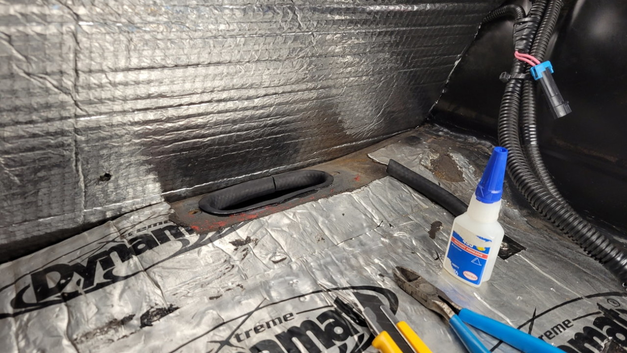
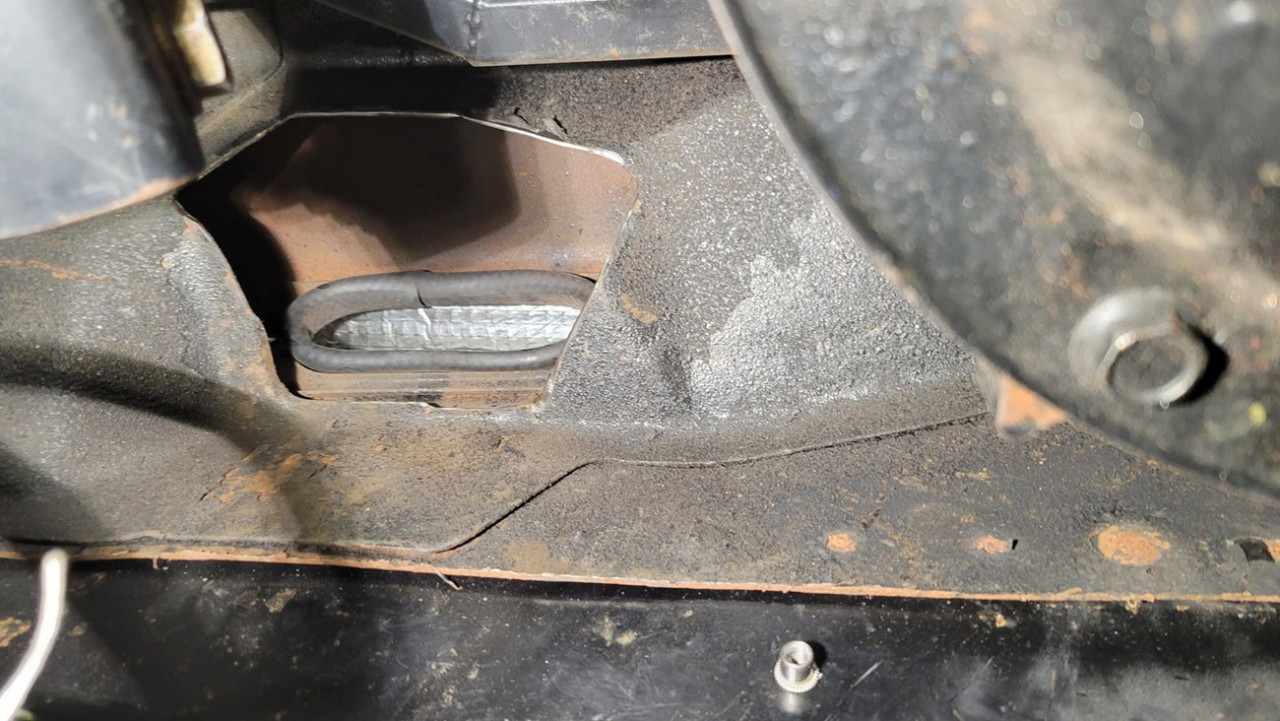
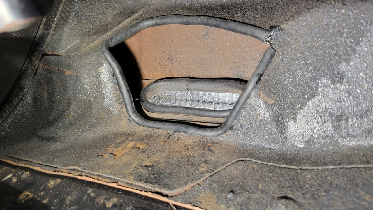
To let all the hoses pass through the trunk floor (6 hoses total: 2x -8AN, 2x -6AN, and 2x 3/8" vent lines), I needed to enlarge the factory hole for the vent lines. I chose to make this hole as big as I possibly could to avoid kinking any hoses or forcing any awkward hose routing bends, and I glued split-rubber-hose to the edges to add some wear protection...
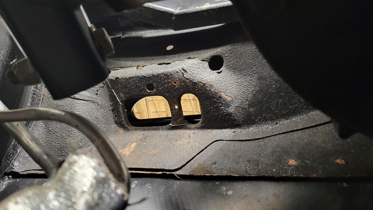
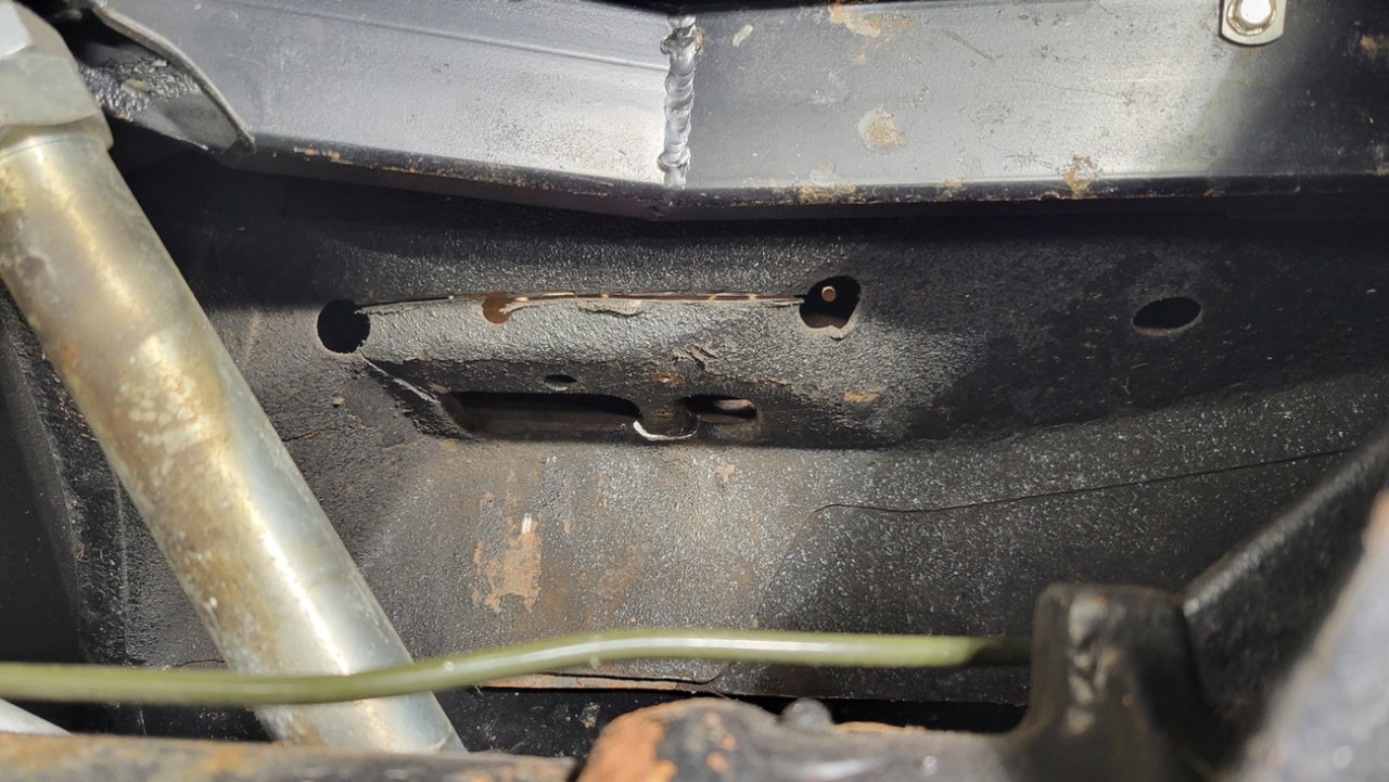
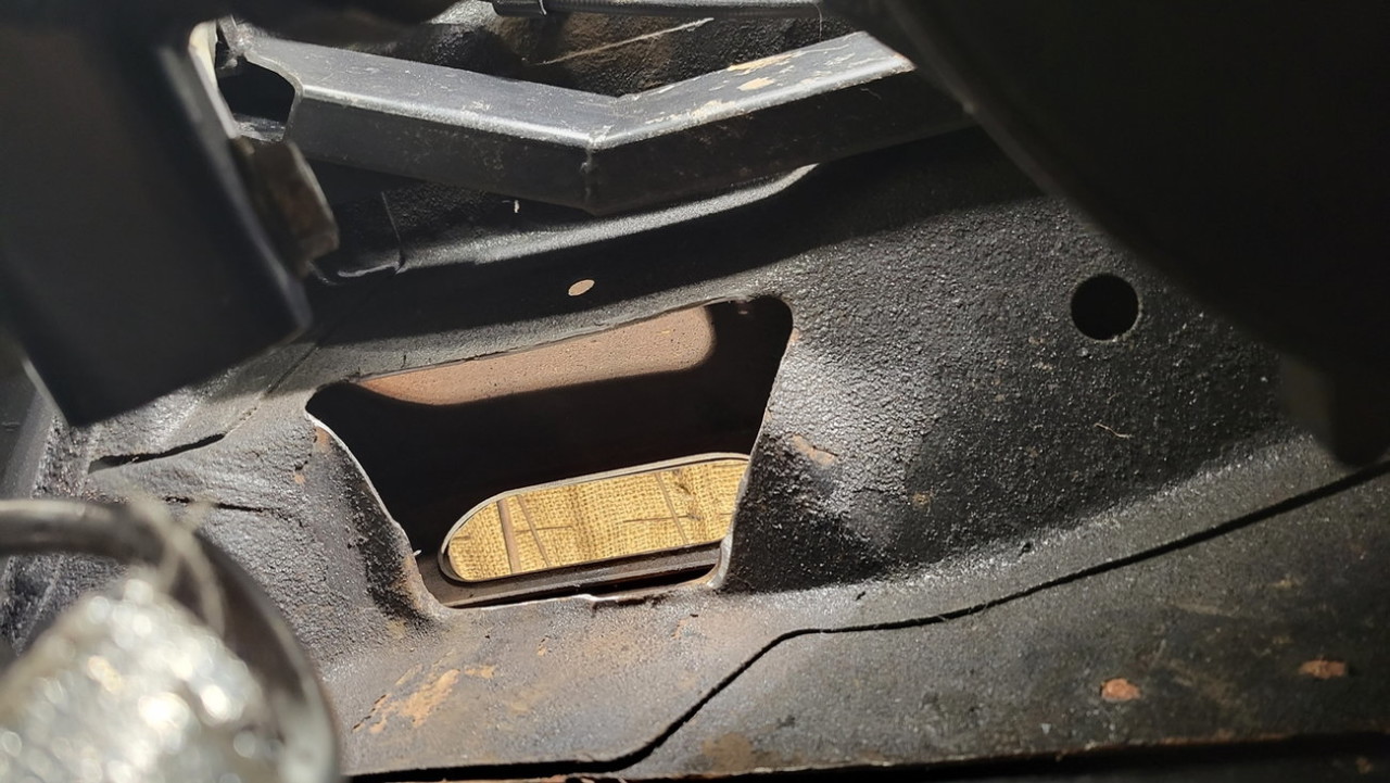
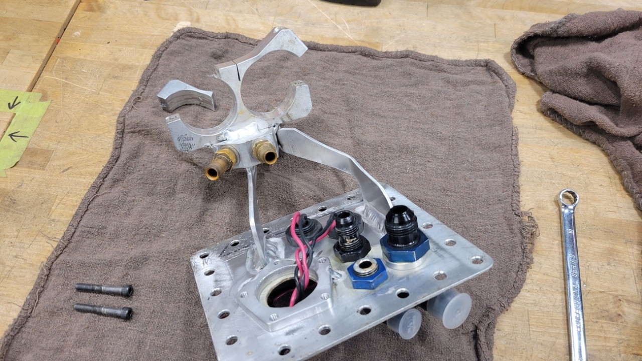
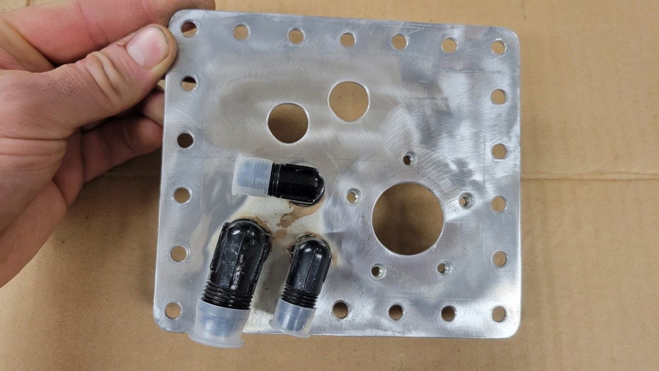
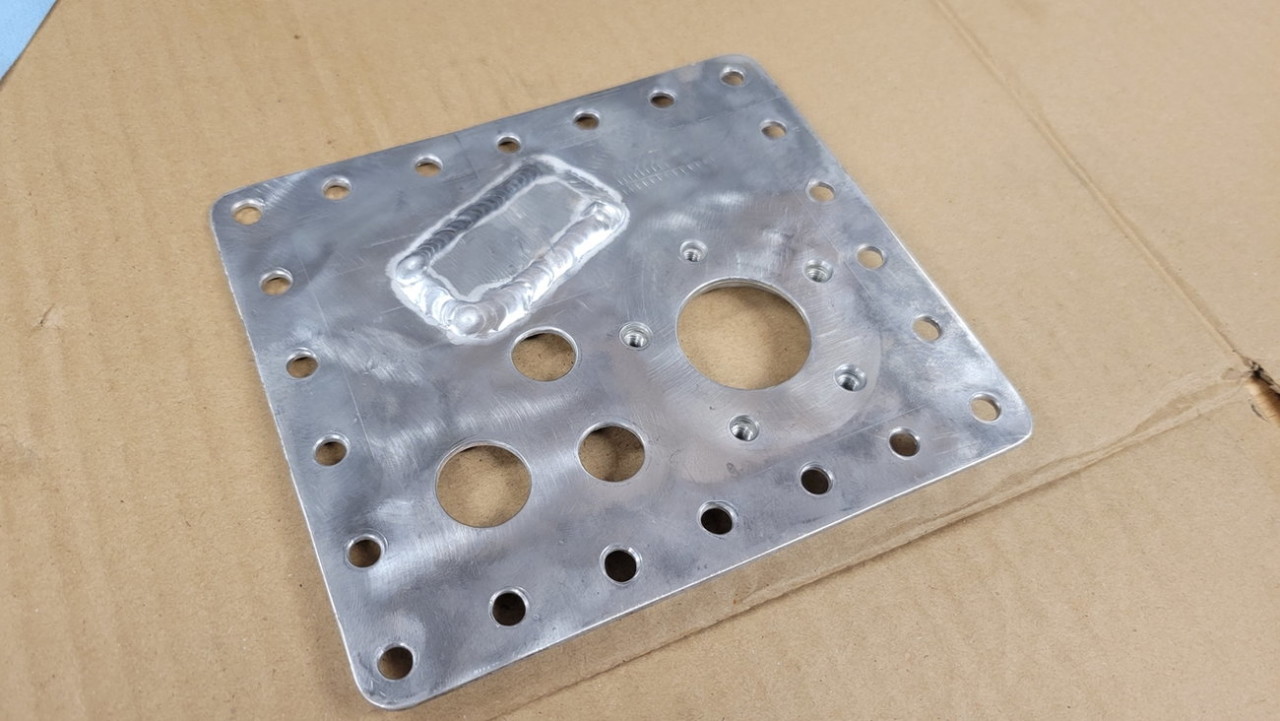
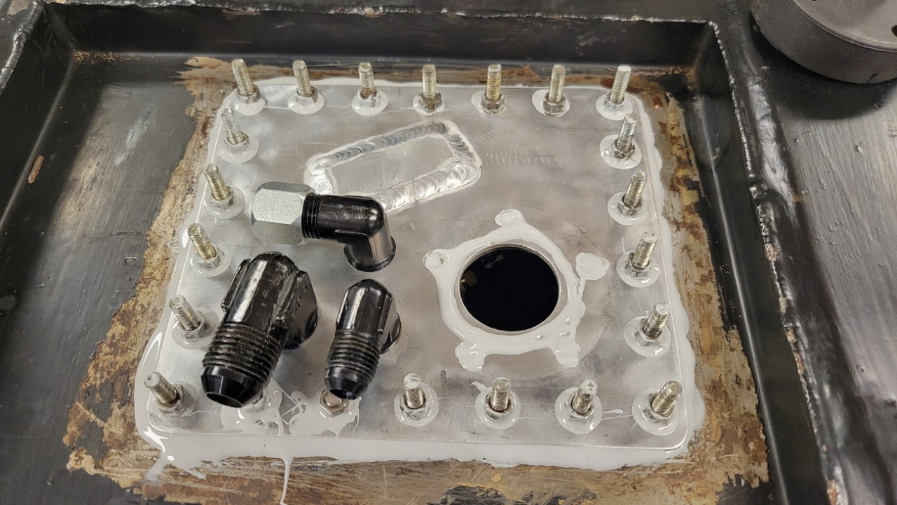
Next I had to update and simplify the gas tank part of this new system redo. I needed to seal up two holes which were previously for the individual pump wiring pass-thru grommet.
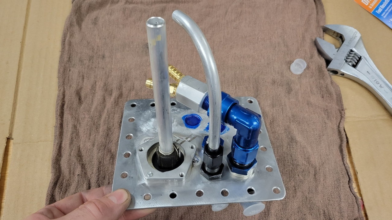
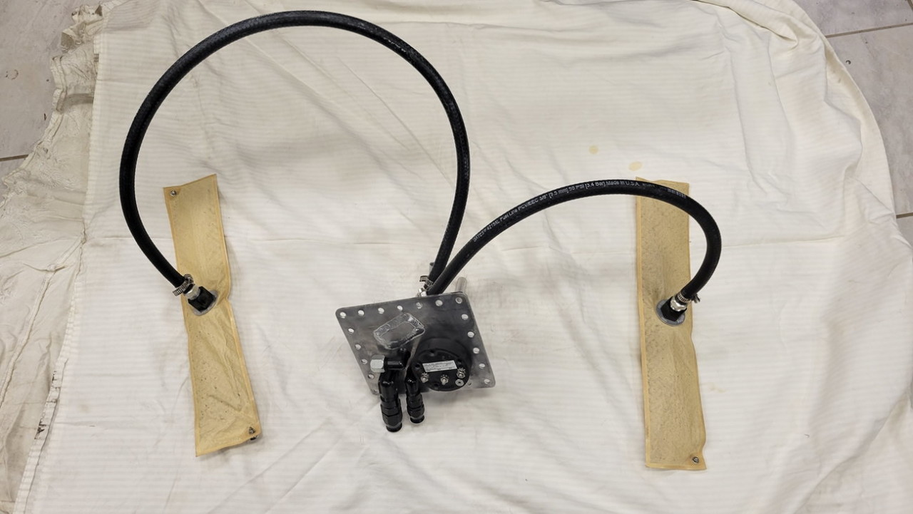
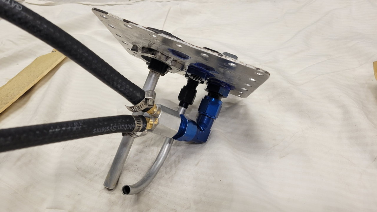
I decided to keep the Holley Hydramats.. since they work well and in the past I have literally sucked the tank dry before the engine starved of fuel. I decided to do new 3/8" rubber fuel hose to the Y-block I previously made, and then that simply goes into a single -8AN 'supply' port leaving the tank.
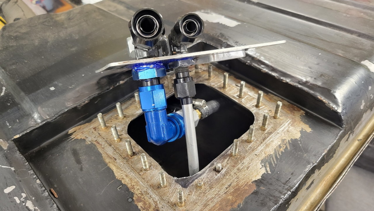
It was SO much easier to reinstall everything back into the tank without having to Jenga a huge mess of pumps+hoses through the access/bulkhead hole I cut in maybe 2011...
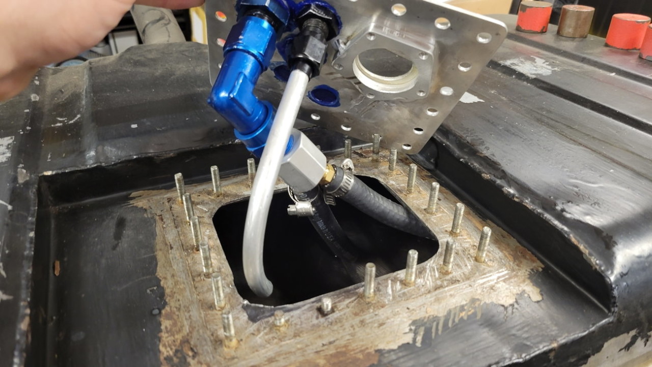
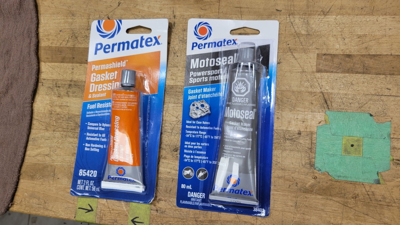
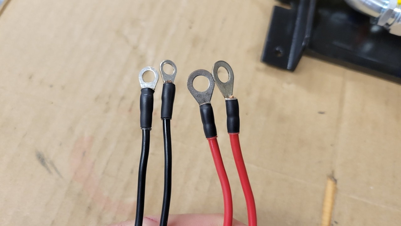
I first tried out the blue colored Permatex gasket dressing "sealant" (shown on the left, below), but after a few days it was just a bit too gummy and malleable for my liking. I then tried out the grey colored Permatex Motoseal, which ended up at a really nice consistency of form-able but pretty stiff.. not rigid, but just enough give to it, which I used on the bulkhead cover plate and all the cover plate hardware...
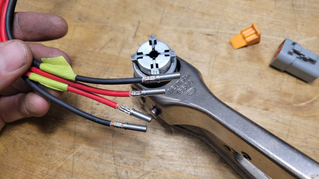
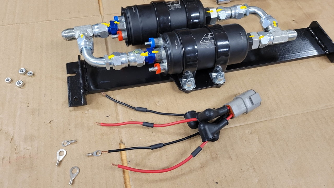
Now to get to some of the wiring. I don't know why everyone dreads this so much.. if you have the right stripper/crimper tools and a bit of a process, it goes quick! And looks nice and clean too, even if done in a home garage.
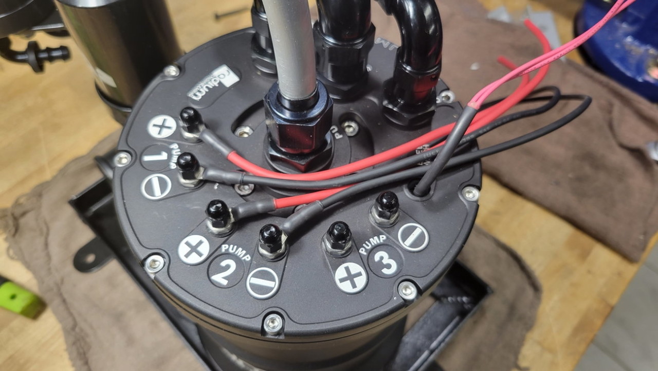
Keeping with the theme of future-troubleshooting ease.. I wanted the pressure pumps to have individual wires and fuses all the way up to the switch solenoid power source next to the battery, as well as separate grounds.. so that a spliced connection of multiple wires can never be the cause for diagnosing any possible future fault.
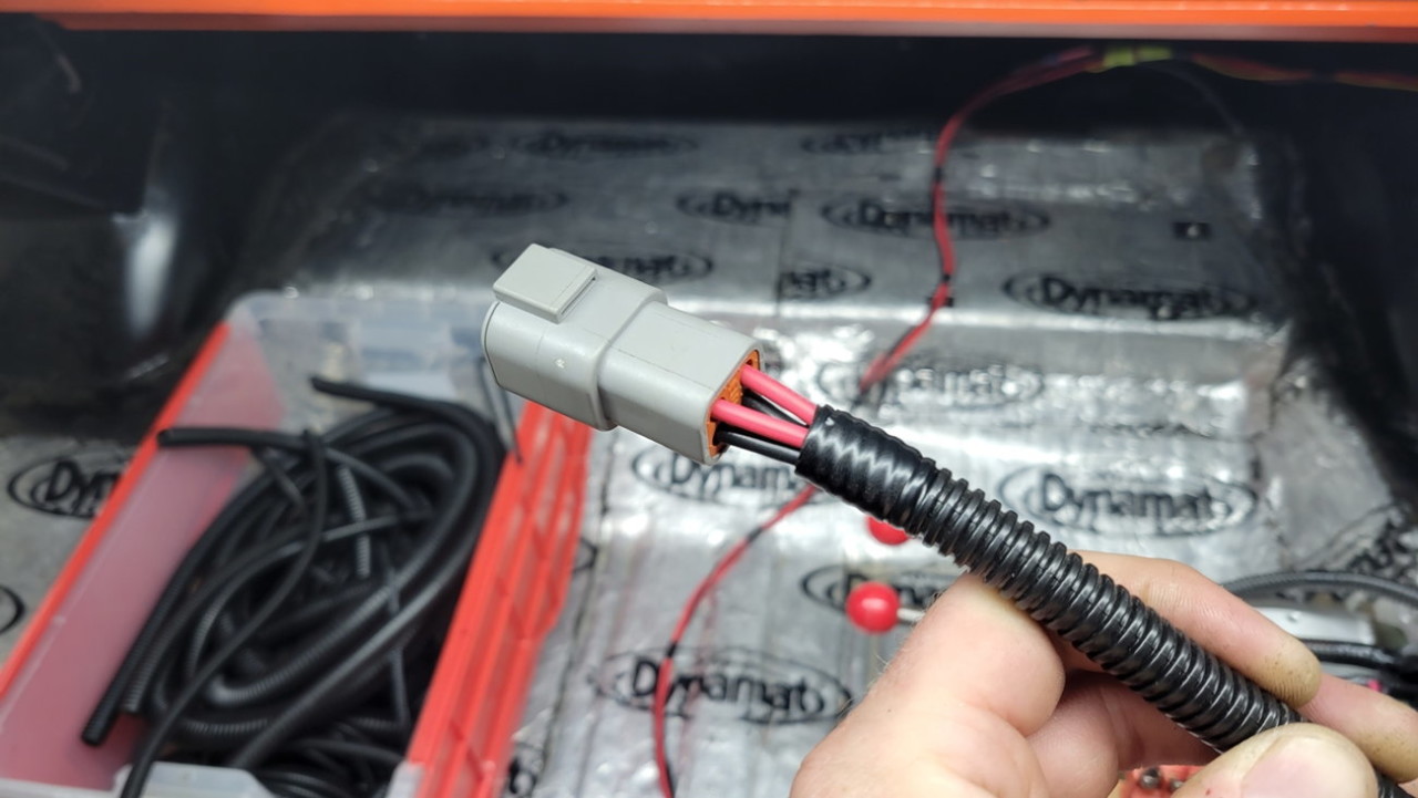
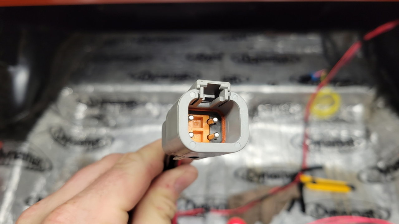
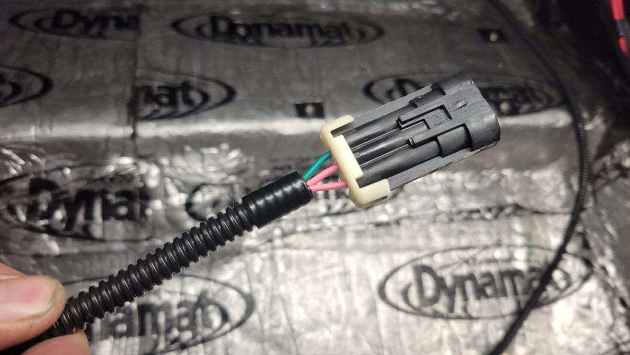
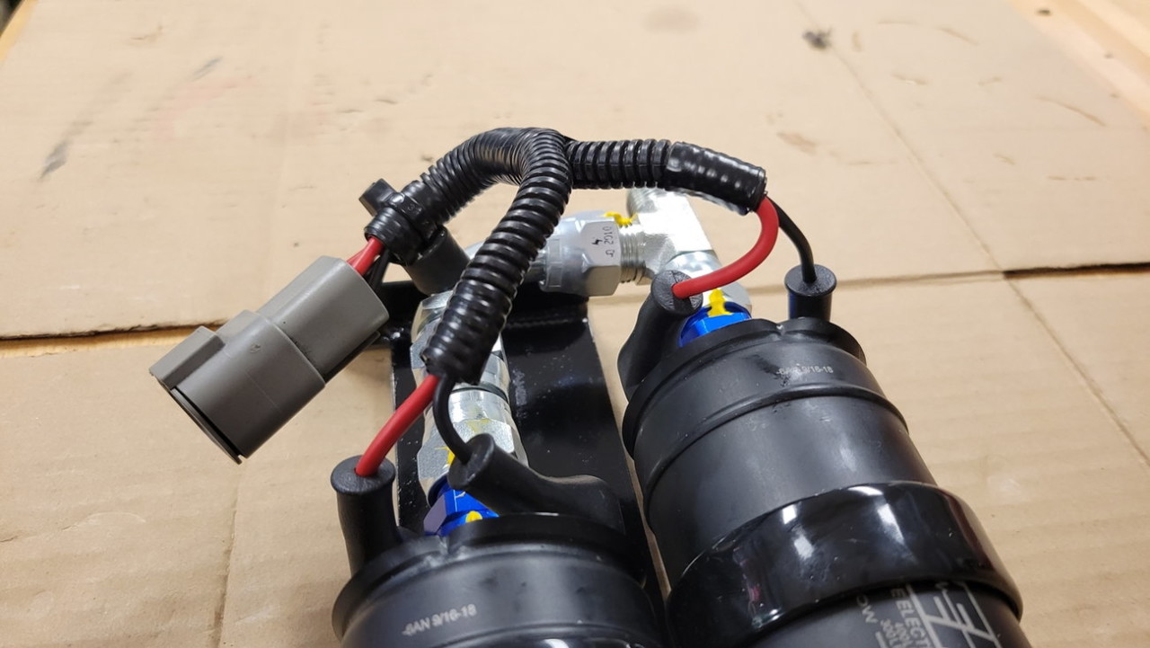
The two pink wires shown heatshrink'd together are a level switch inside the surge tank. If that level drops below "3/4 full" then the two pink wires have continuity... I'll use it to hook up a "low level warning" dash LED to let me know that the lift pump is no longer filling the surge tank to the very top... either from lift pump failure or just that the main gas tank has been sucked completely dry.

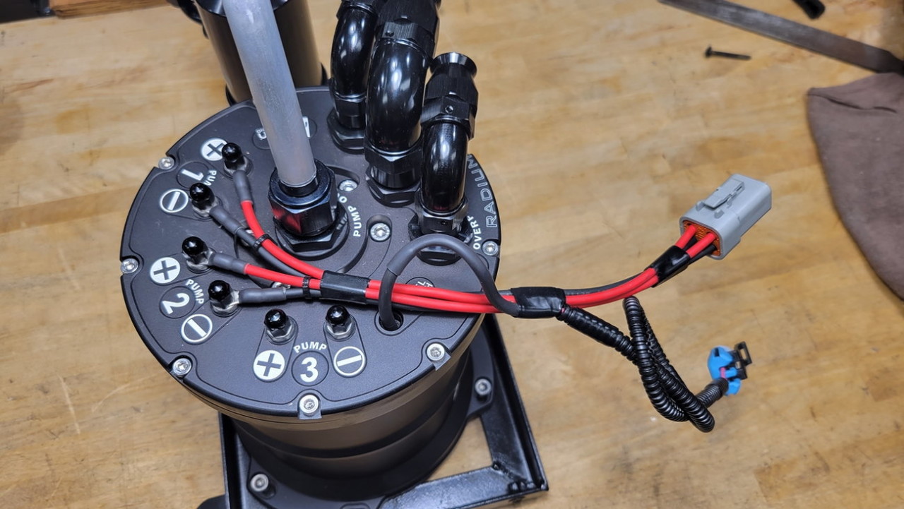
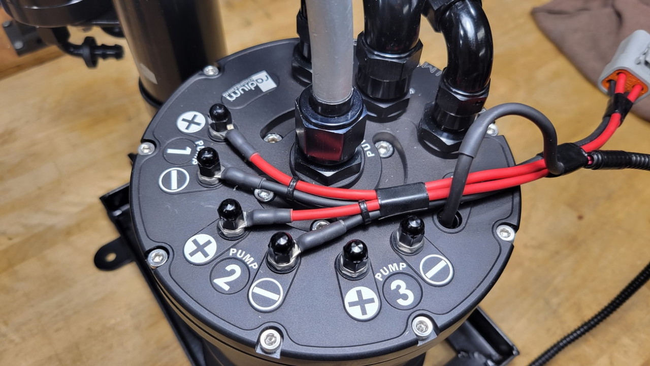
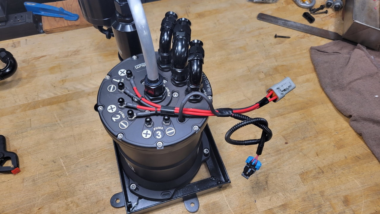
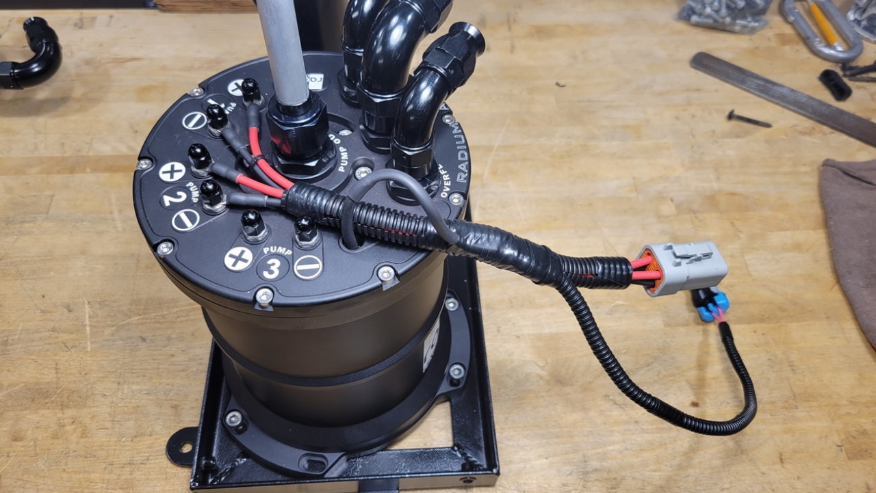
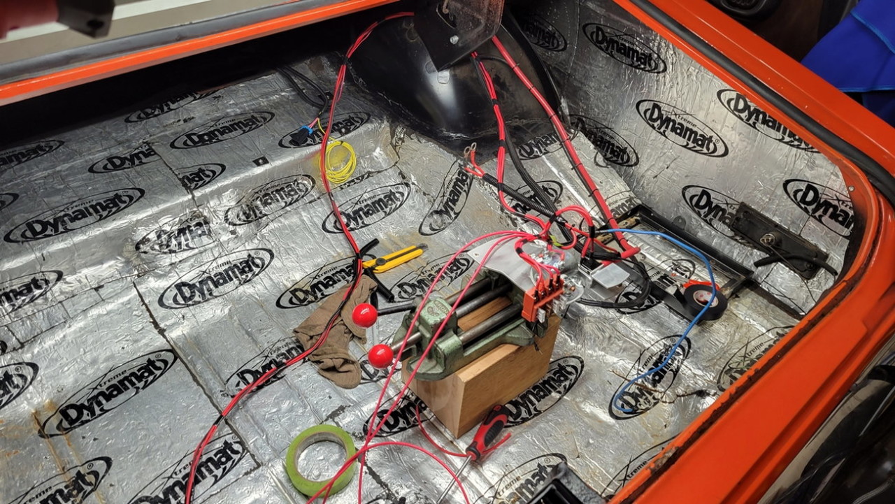
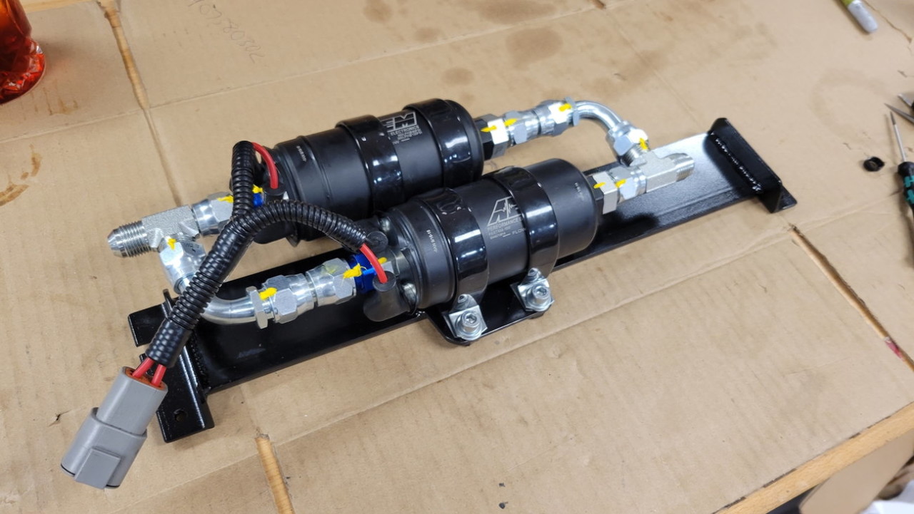
And here is the start of running the lift pump wiring to the toggle switch, and the new pressure pump wiring to the surge tank...
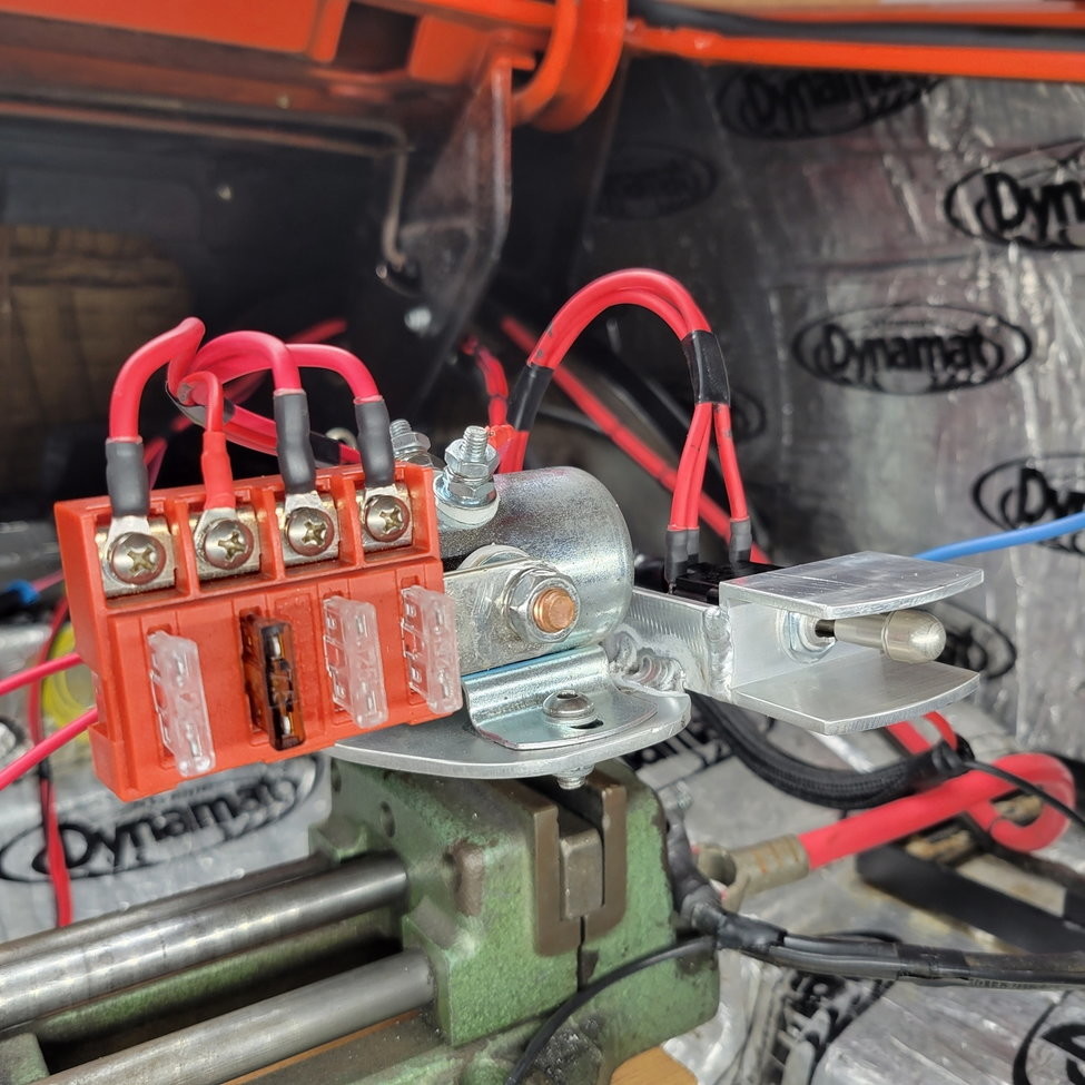
This Blue Sea fused buss bar provides all the power for the fuel system.. the two left 25A fuses are to the individual surge tank pressure pumps, the smaller wire is a 3A fuse to power the SpeedHut capacitance gas tank level sender, and the last big wire on the left is a 25A single supply to the toggle switch, which then delegates the power to either lift pump.
The wiring on the lift pump is the previously-existing 10ga wiring, so it's incredibly overbuilt for this new lift-pump application. The name of the game here is overbuilt with quality, trustworthy materials, redundancy when possible, and as much circuit isolation as possible for future diagnostics. On that note, the 25A fuse for the lift pump is also massively oversized, but it can then serve as a backup fuse for either of the pressure pumps if need be, since I can choose to run only 1 pressure pump.
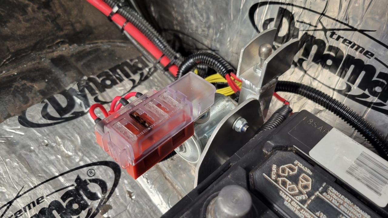
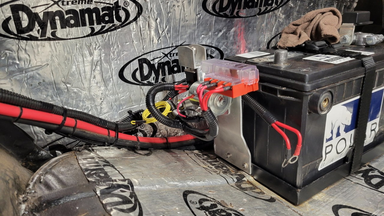
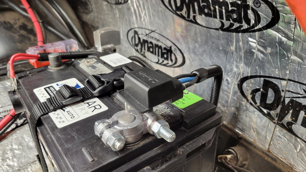
Also wanted to clean up some old battery wiring work circa 2013, that isn't up to 2022-Joe standards.
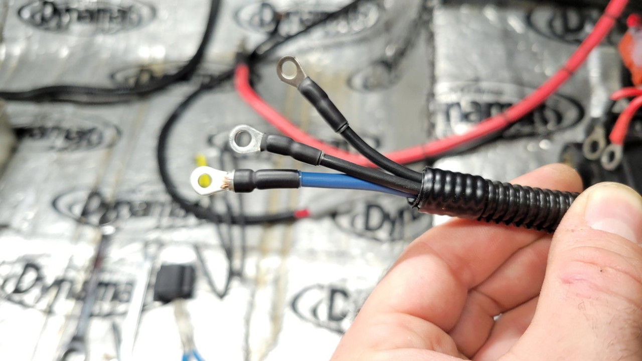
The old positive terminal was made out of some **** pot metal, and after enough tightenings it started to crack... so I got a higher quality terminal, hydraulic crimped it on, then used some 3:1 heat shrink with adhesive for a nice mechanical bond....
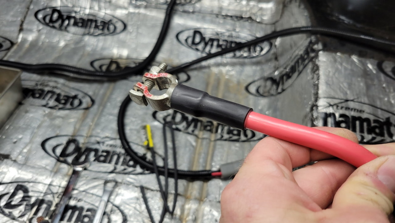
With a previous failure of spliced grounds from the gas tank pumps into a single ground wire, I decided that the new pressure pumps will have their own ground wires direct to battery. The repair I had to do previously was the blue wire, however it is now two 12ga wires tee'd together into that blue 10ga wire, about 8" away from the negative terminal.. so I'll let that splice slide in this instance since I'm not about to cut the tee out and extend two wires.
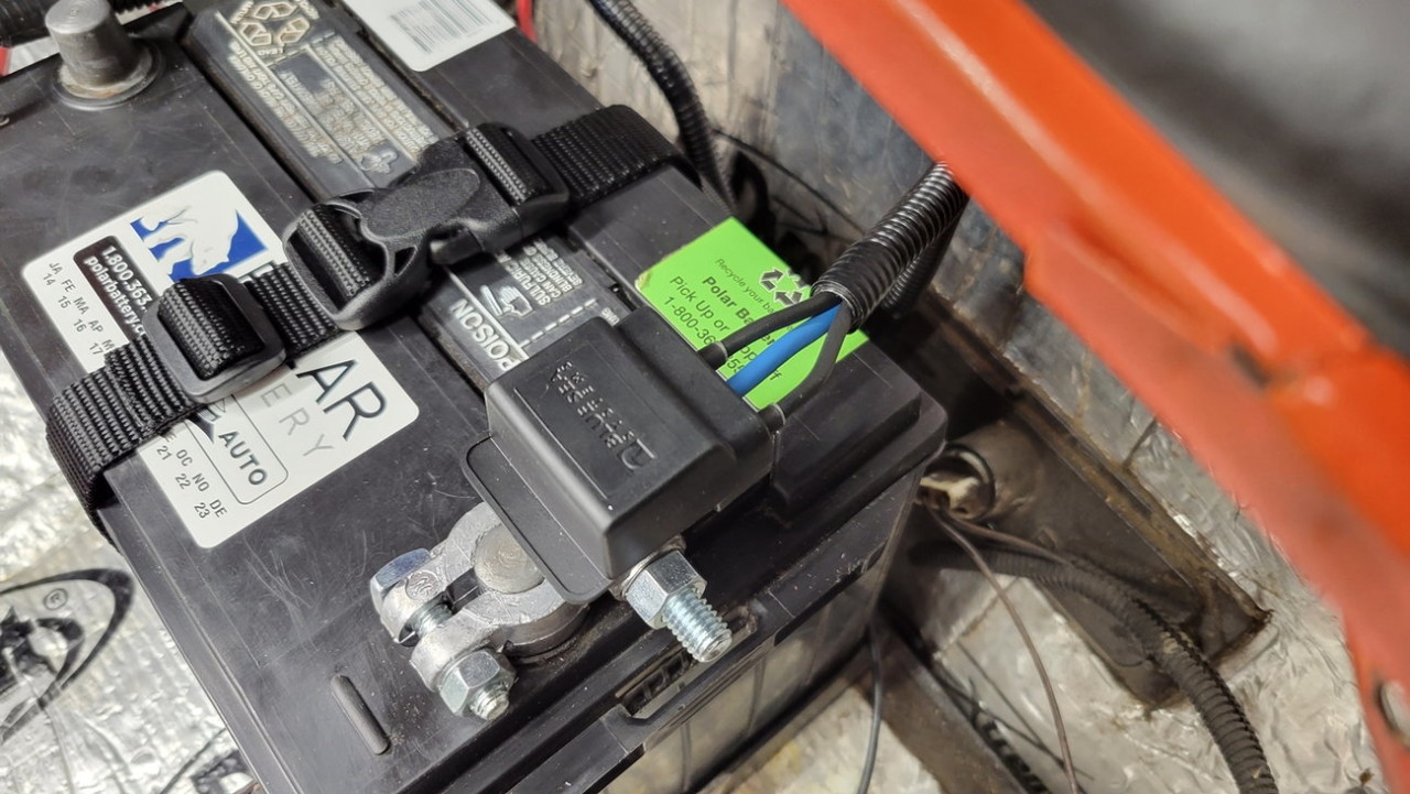
All the ground wires are connected to a Blue Sea grounding plate buss bar thingy, that I bent 90 degrees to fit more cleanly while using the accessory bolt on this military-style battery terminal...
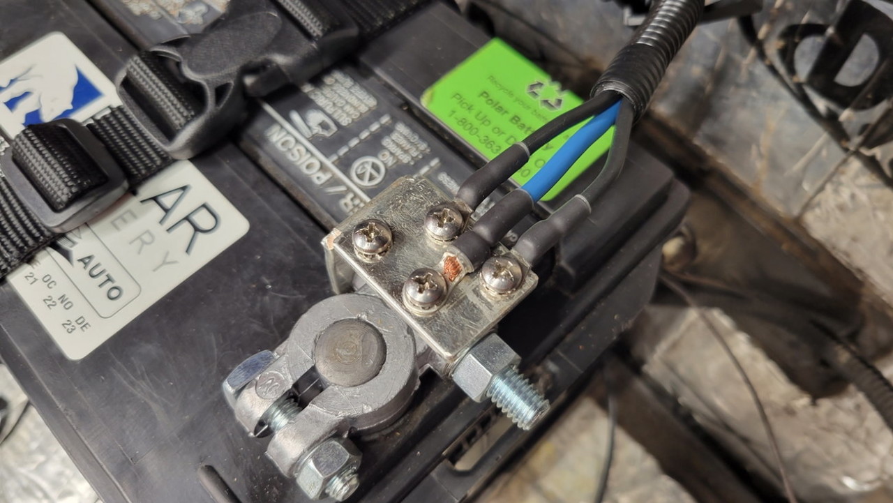
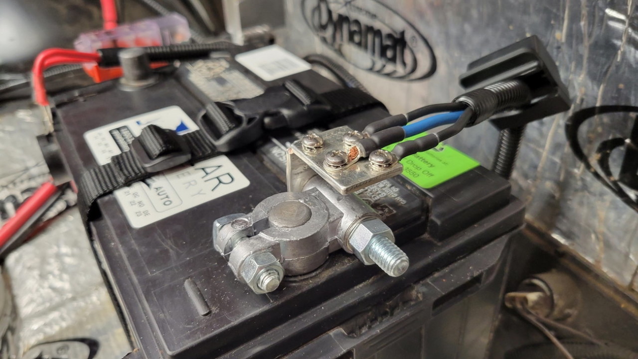
It even has a sleek black cover to designate it as negative, and hide the connection points...
And here is some "signal wires" that I had to run from the tank up to the dash area... two pink wires for the surge tank level signal, and a single green as a future "boost reference signal". I already have a boost-referenced Holley output (set at I believe 4psi) going to a relay under the dash, which turns on the T56 fluid transfer pump, so if I ever feel like staging the pumps I could tie this grene wire to that relay, or to an additional Holley output...
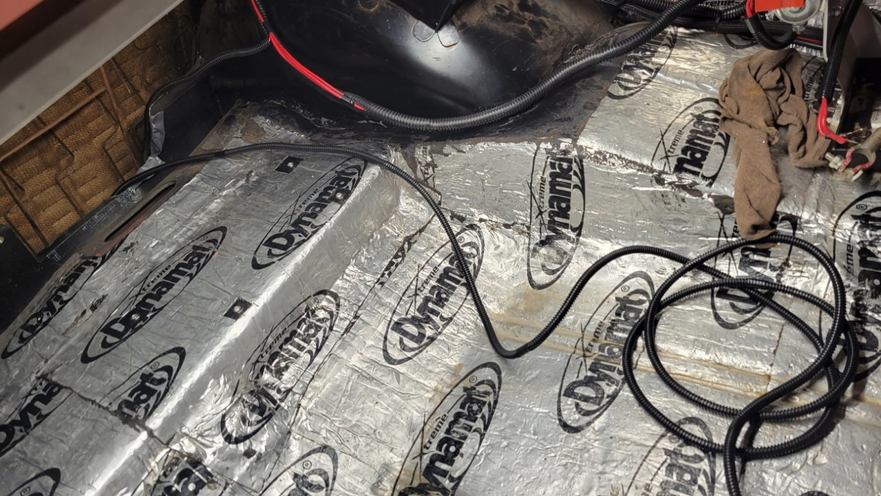
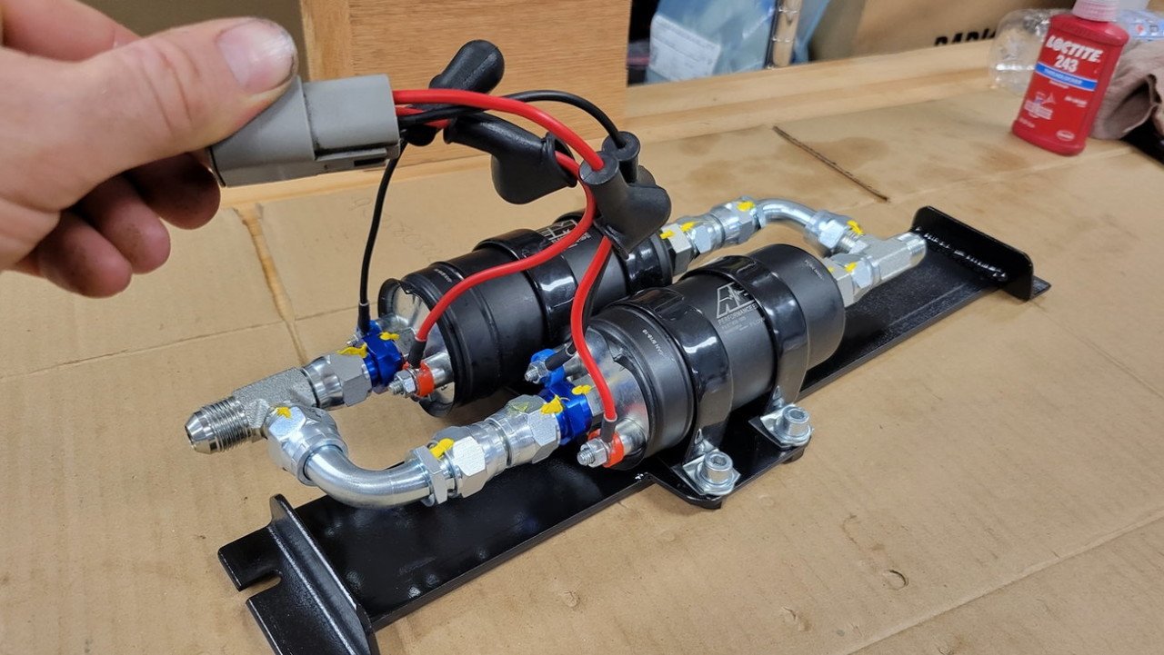
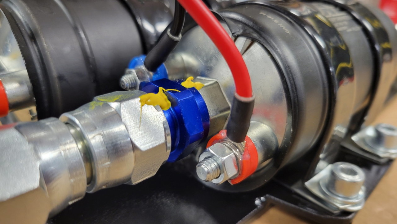
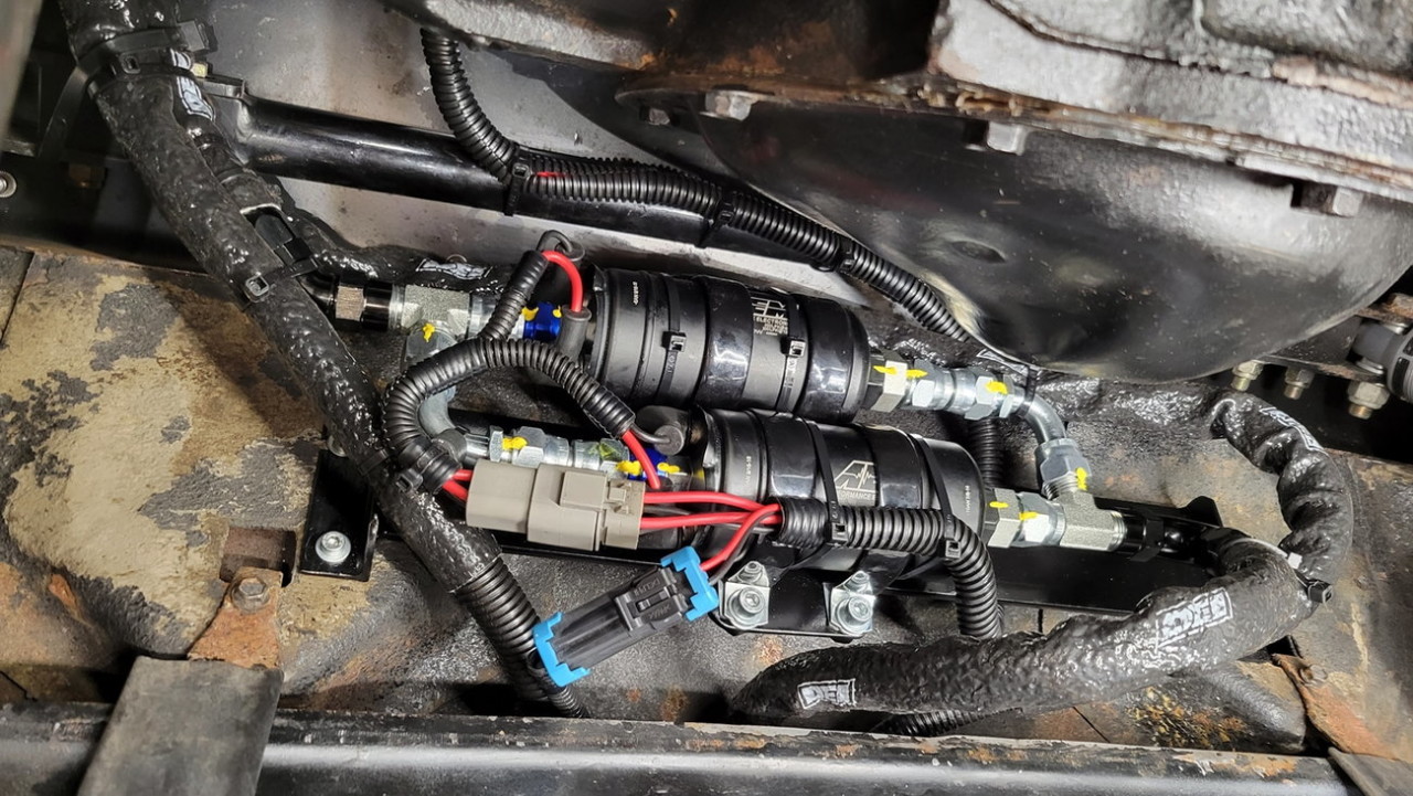
And some more wiring, now for the lift pumps. Since they're in an "exposed" place under the trunk area behind the rear axle (like hell it's ever going to experience mud or water again down there), I did the usual adhesive heatshrink, plus dielectric grease on the ring terminals and studs, as well as used the AEM-supplied rubber terminal boots, and then split loom for wear/spray protection, and a rubber hose standoff as a strain-relief tie down to finish it all off.
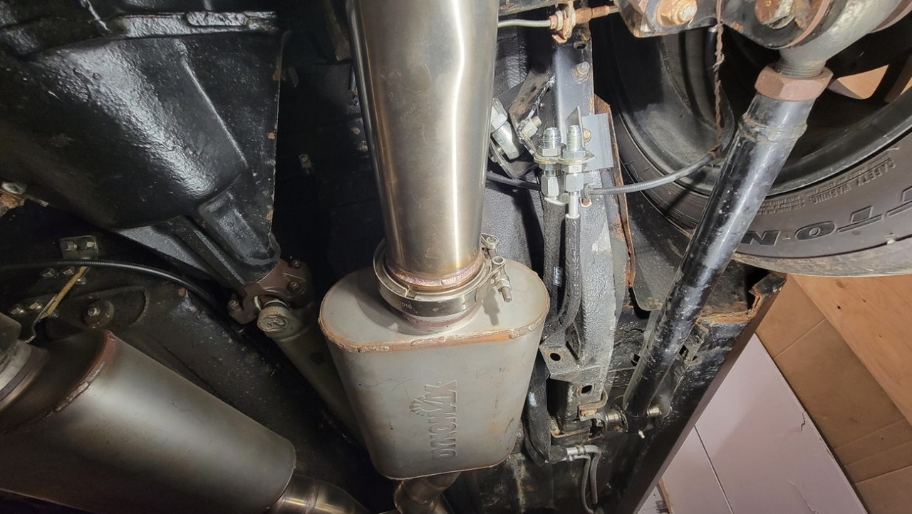
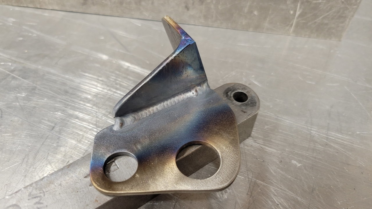
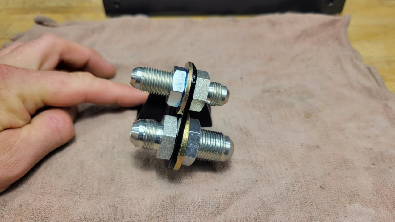
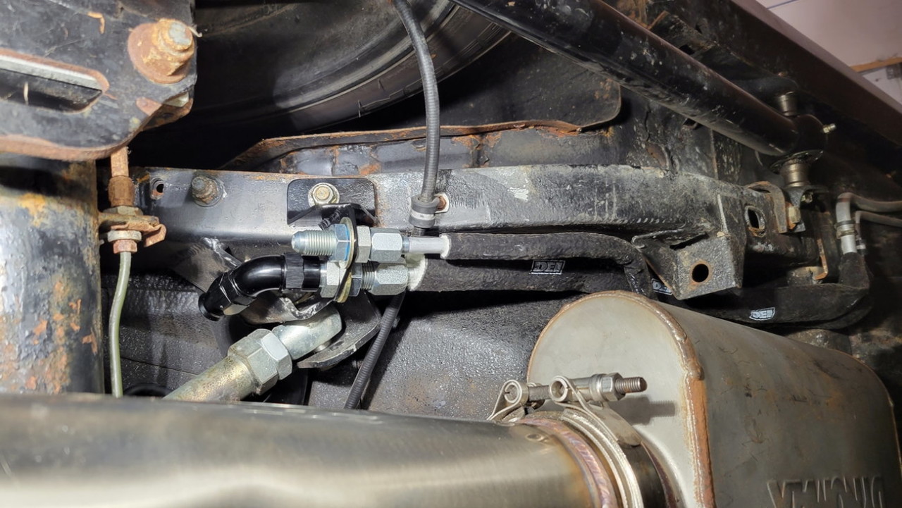
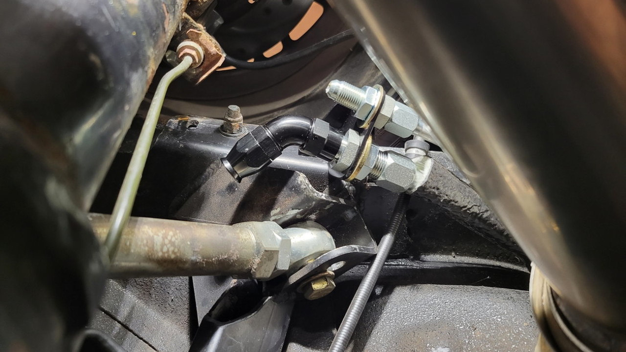
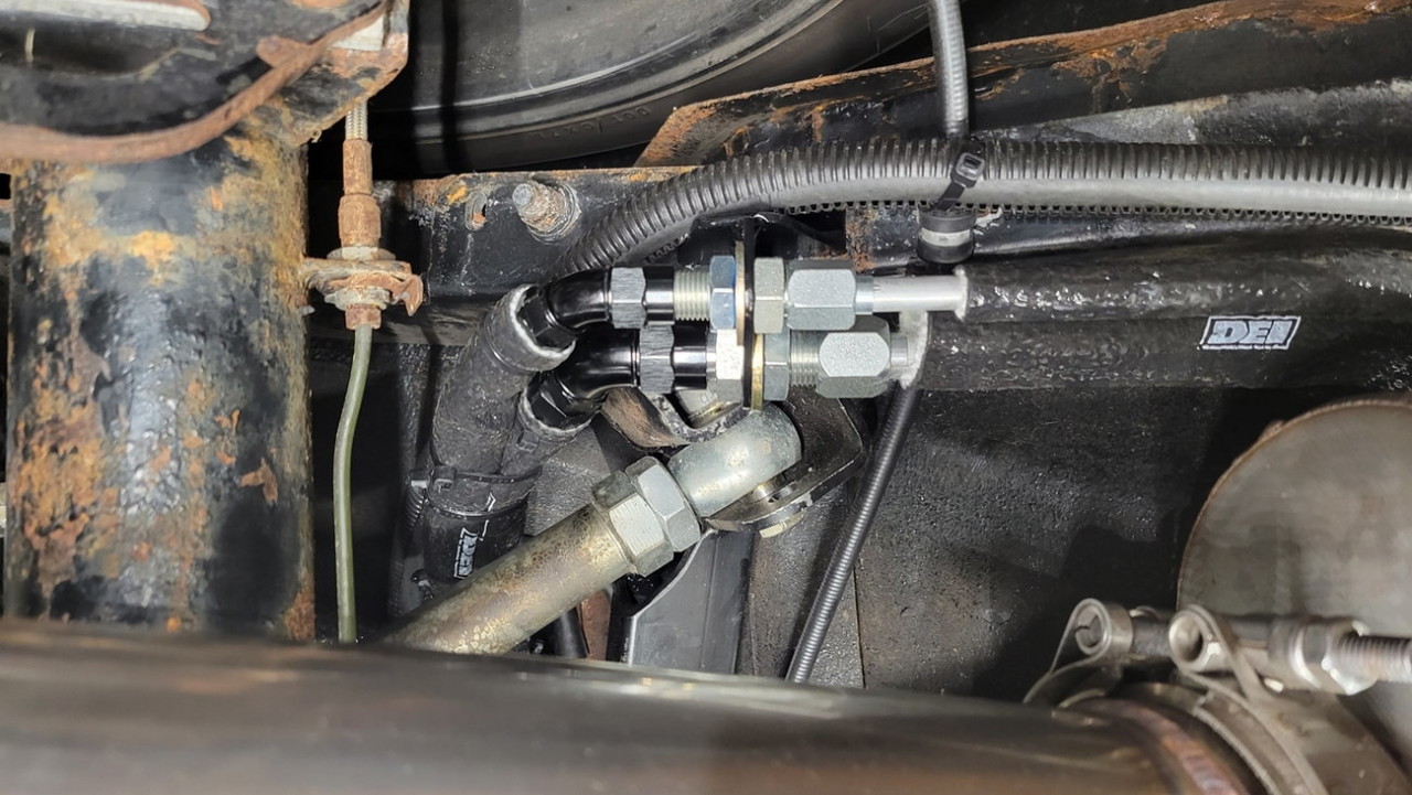
Next up, I wanted to redo the fuel hard line around the rear axle, and how the new hoses would connect to it. I tried bending the original fuel line (shown in 1st pic below) but it so quickly started kinking and crimping itself, so I said screw it and cut the hard line all the way to the 4-link UCA mounting area on the chassis. I then made a bulkhead fitting bracket, to exactly hold the hard line at the perfect angle for 45 degree hose ends to aim at the trunk pass-through hole.
And yes, that fuel line is close to the muffler.. however I ran it for years without any heat insulation and zero problem.. so I figured while I had lines knocked apart I might as well sleeve it all with heat insulation.


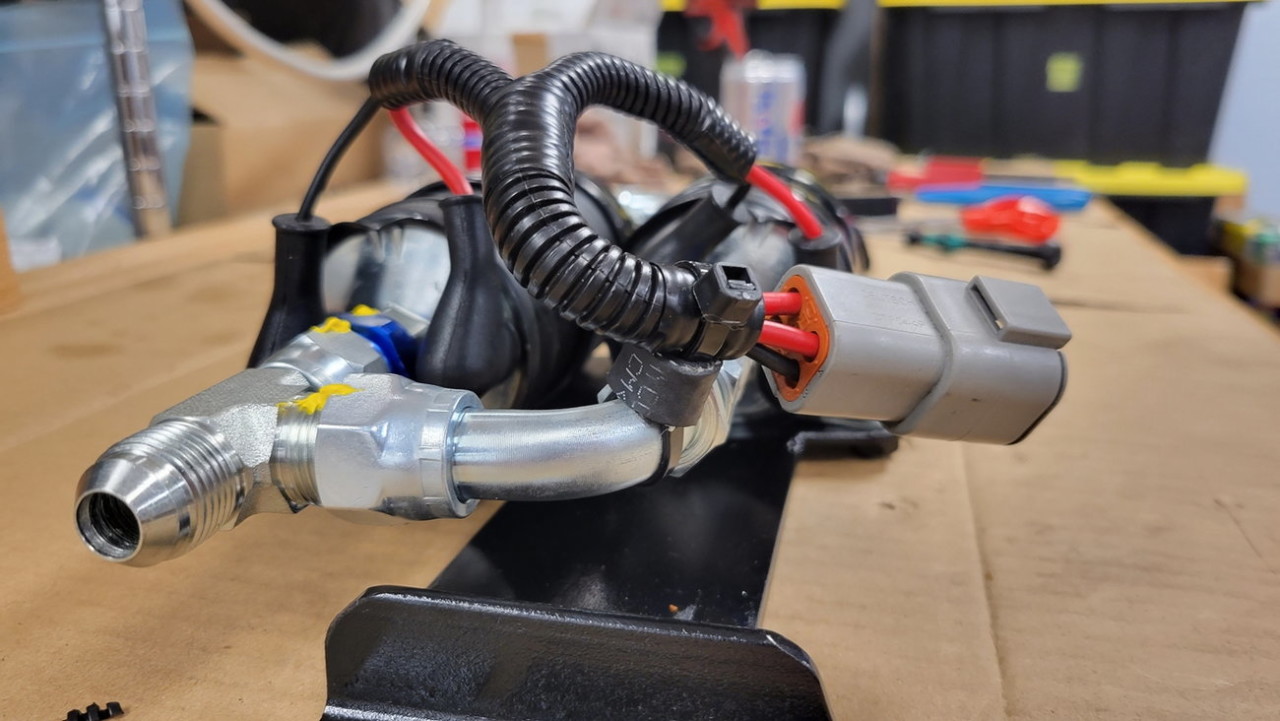
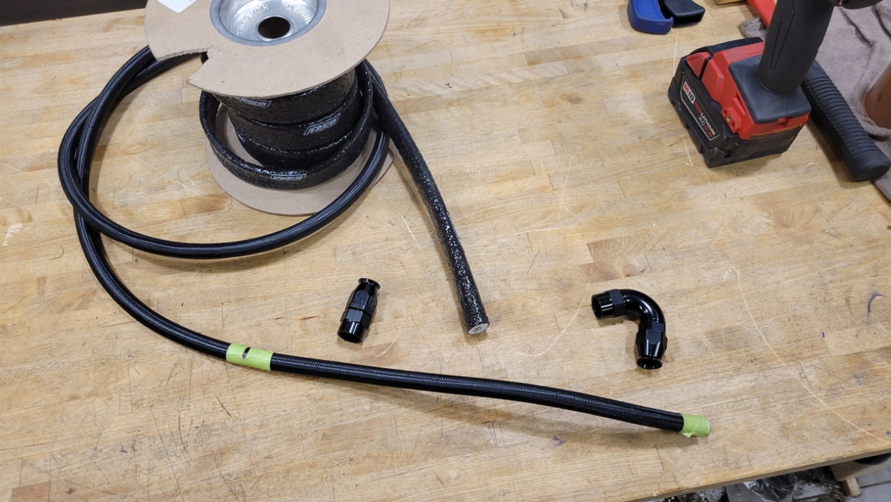
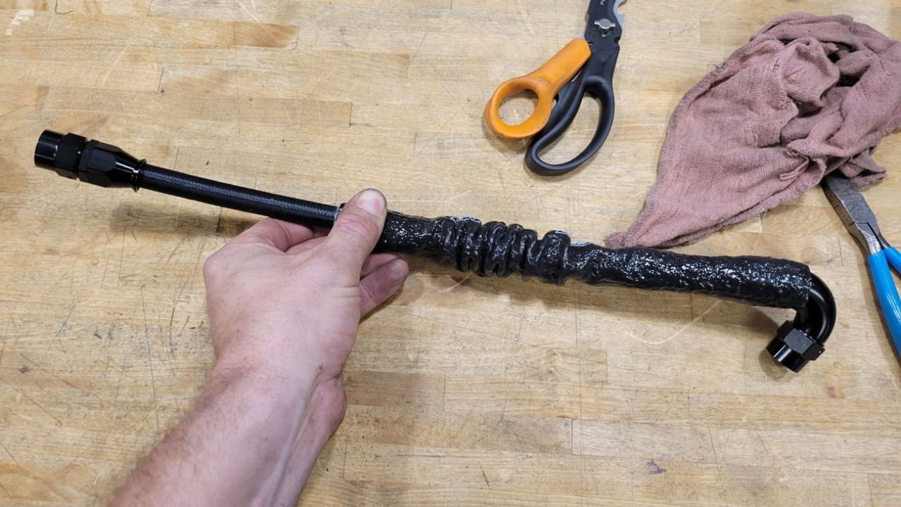
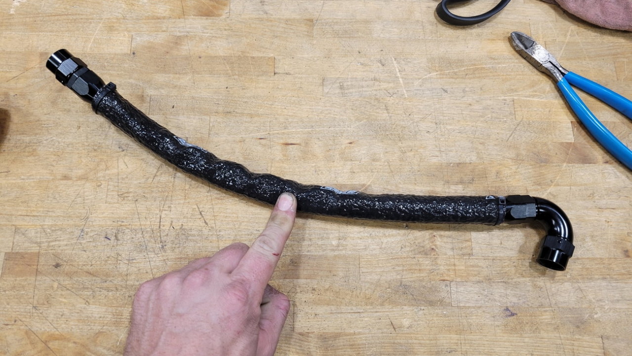
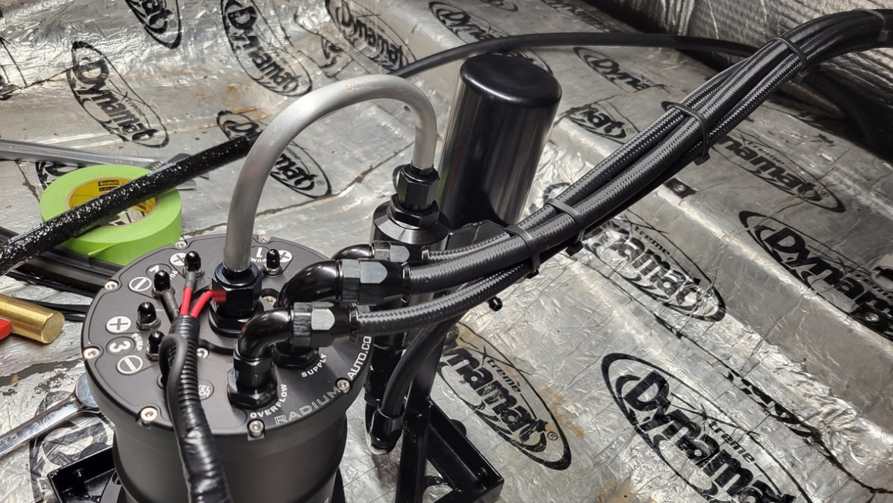
And time for final assembly. I've never used Vibrant hoses before.. and truth be told I'd much rather have used Earl's UltraPro stuff since it's so flexible, light, and easy to assemble the hose ends.. but it appears they haven't made it in 6-AN sizing for some time, and sometime recently stopped making it in -8AN too... bummer. The Vibrant hoses went together without issue, and no leaks.. but it's the dreaded stainless weave so of course you're going to jab that cut end under your fingernail a number of times.
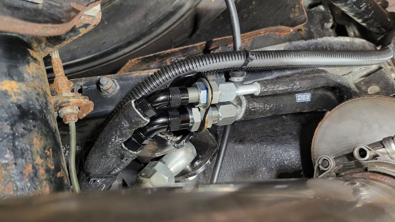
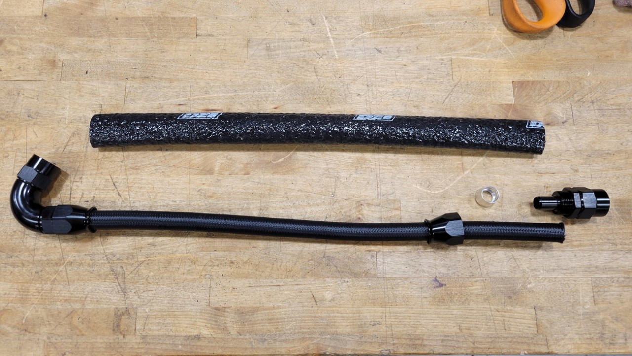
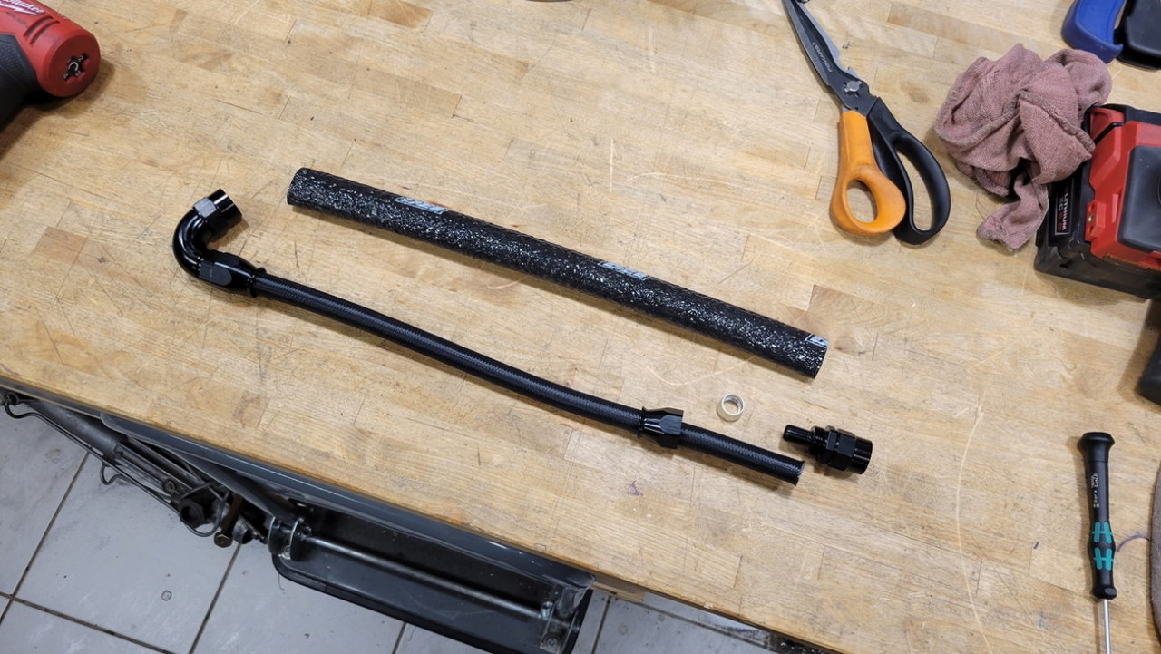
I made sure to have all hoses get DEI heat insulation sleeve on the hose segments leading up to where they pass through the trunk floor into the trunk, and here's a brief step-by-step of how I assembled them (this hose shown connects the gas tank to lift pump inlet)...
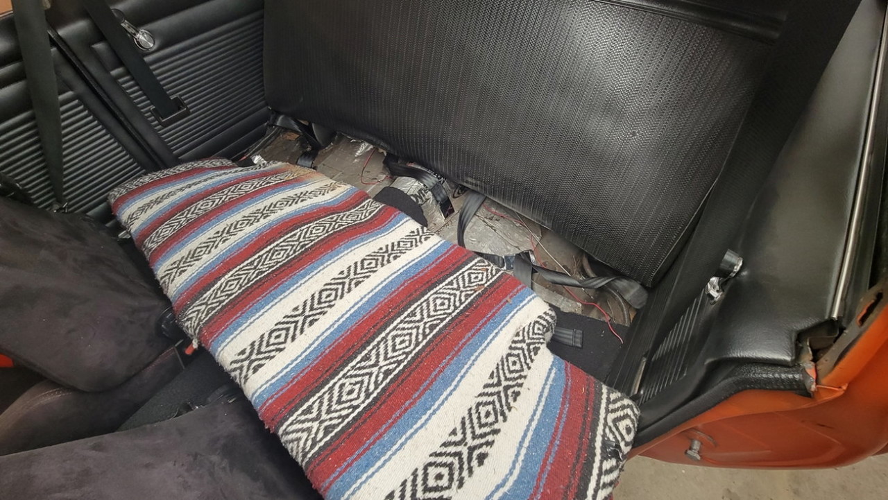
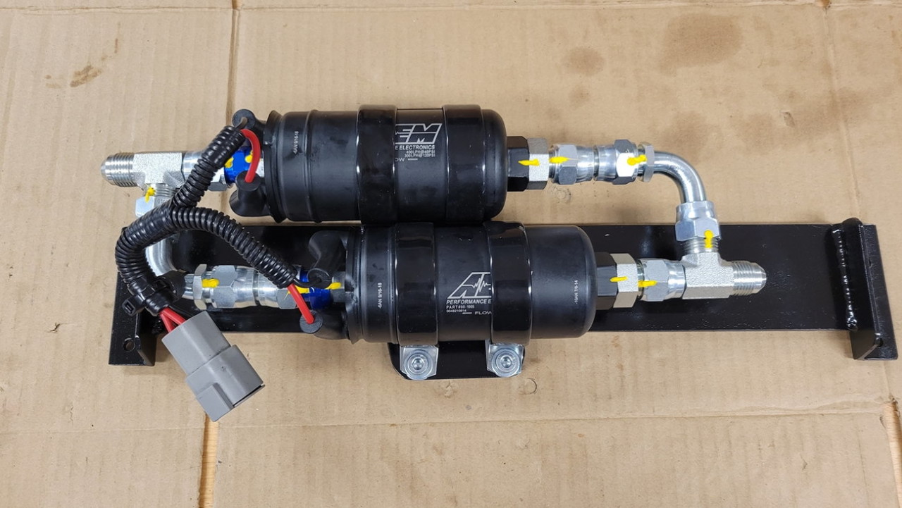
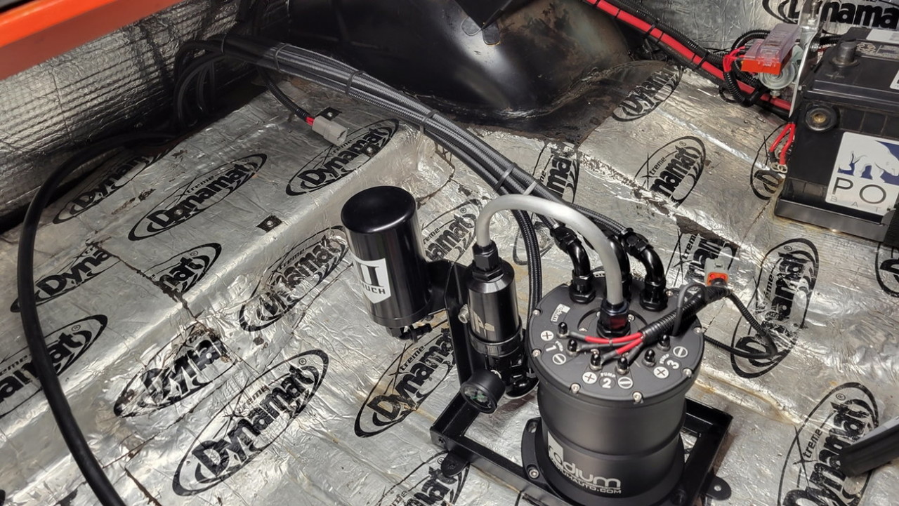
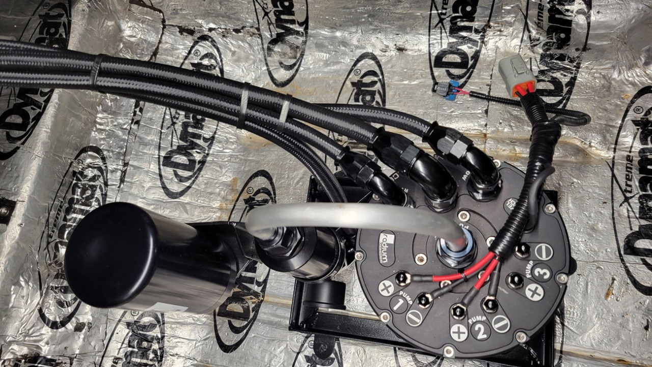
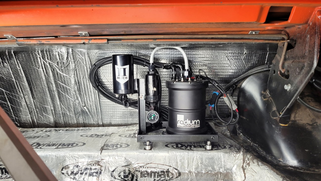
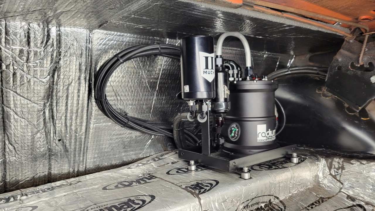
And here is all the hoses run.. notice I left enough length in the hoses so that I could unbolt the surge tank assembly frame from the trunk, and swing it out closer to the rear bumper for easier inspection/diagnosing if that should ever be needed...
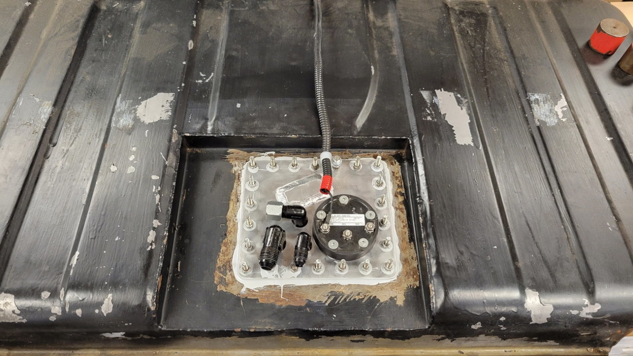
And mounted in place, to the trunk floor using four M6 screws into M6 rivnuts...
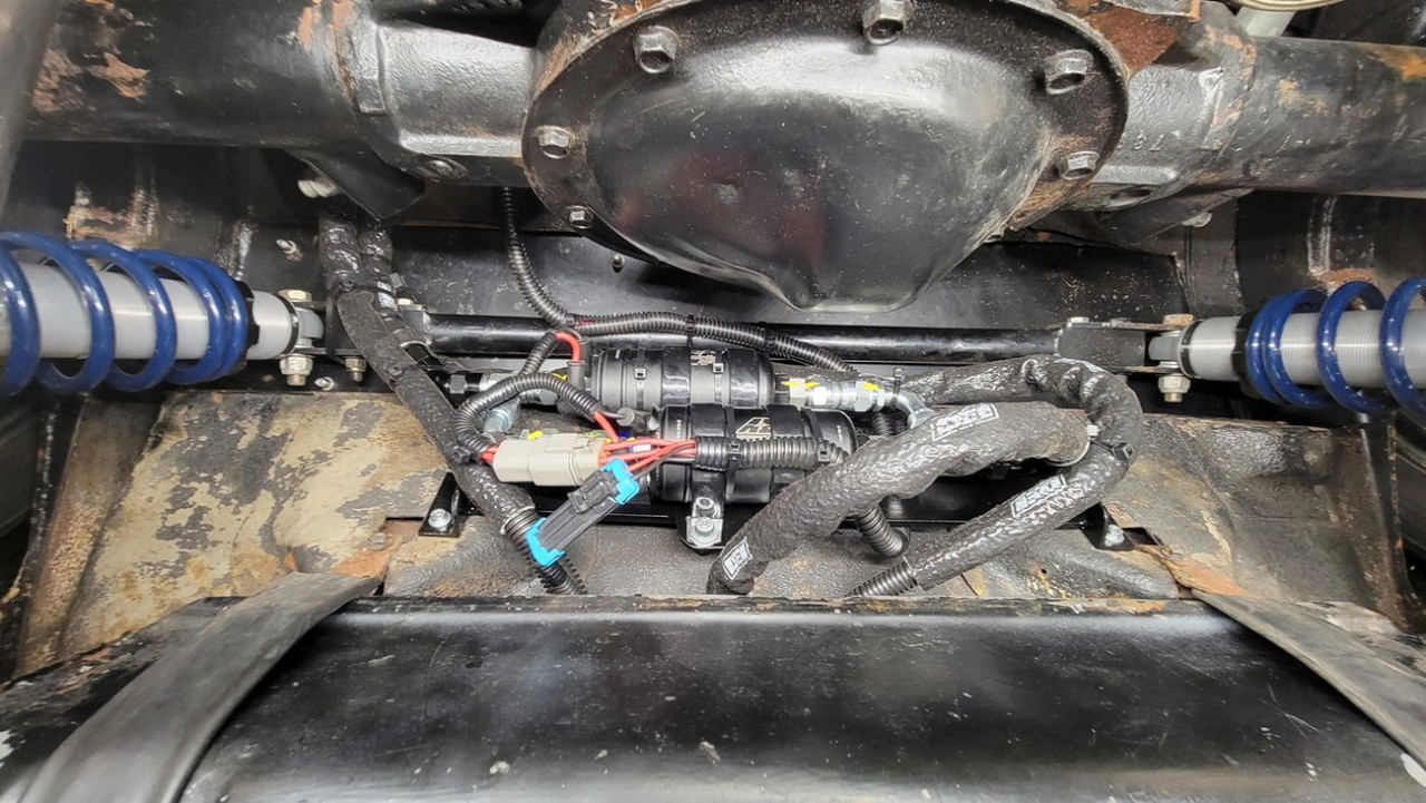
And some very awkward/terrible pics of the lift pump assembly installed in front of and just above the gas tank, with a couple inches of clearance to the diff cover (hard to see from the angle and camera fisheye effect).. so far zero issues priming the lift pumps considering they're ~4" above the top of the gas tank...

Wow thanks for sharing!
Posted by Diggymart on 3/3/19 @ 12:40:25 AM