You must be logged in to rate content!
11 minute(s) of a 391 minute read
11-29-2009
Some updates!
Okay I am procrastinaing horribly today. I need some fellow vortexer motivation to get cracking on this....
I got the heater all back together and working. Everything wired in. And then I went to start the car and somehow the heater core is now fouling with the gas pedal. WTF? Figures.
I was struggling alone to get the box back up in place and the hoses are a super tight fit through the firewall. Might leak through EVERY OTHER gasket in the car, but not that one.... So I left the core loose and the side cover off. Thought I had got it correctly repositioned as it all slid into place, but I missed something.
Hoping my buddy T3Raposa will stop by inna bit and give me a hand so I am not pulling it compleatly back out! If so, as usual, I am sure mayhem will insure!
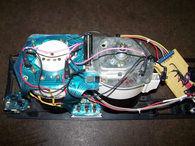
While I had the wiper assembly out, I went and paid WCHLVR's MK1 to MK3 wiper motor upgrade DIY some attention. Got the motor swapped out for one of the MK3 motors I grabbed for it. AMAZING UPGRADE! And we learned a thing or two too!
As fate would have it, I killed the maingear for the MK3 wiper. But VW's are big Lego sets and turns out that the original MK1 gear swaps right back in.
Also I got bored and opened up the motors to take a closer look at them. The motor windings are SUBSTANTIALY bigger for the MK3 motor.
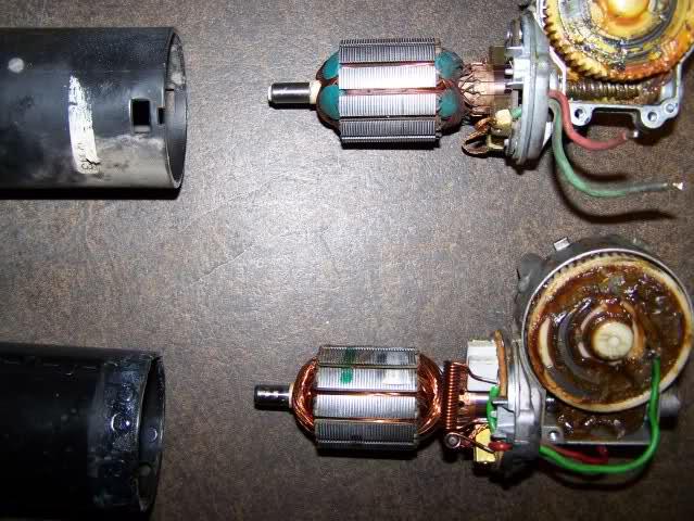
The one with the green putty is the MK1 motor.
A couple days before I pulled this all apart, I lost all my instrument lights. Now I have lost ALL my lighting. No parks, headlights, everything is out. Not sure what happened. Obviously I have checked fuses, but something is goofy. Hoping to get this sorted out and everything back online today.
Hope everyone had a good Thanksgiving!
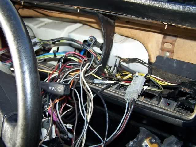
Anywho! Pushing buttons was way helpful! Dan (T3Raposa) and I managed to sort out the wiring issues in under 30 minutes. There is a lot of "randomness" going on in there but short version is the wiring going to the radio shorted out and did some weird things. It was hooked into the parking light circuit somehow.
There were a handful of blown fuses too. Once the wiring was sorted, things rewired correctly, and more fuses replaced (including all the ones that I had ALREADY CHECKED grr) we were all back online.
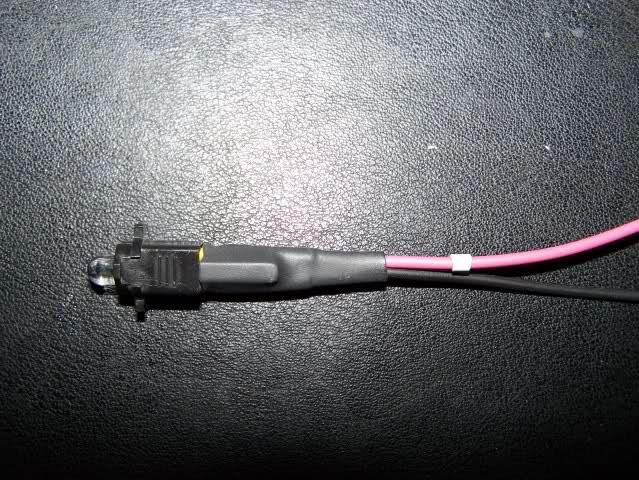
Here is what we started with today and would explain a few of the weird and random issues I was having.
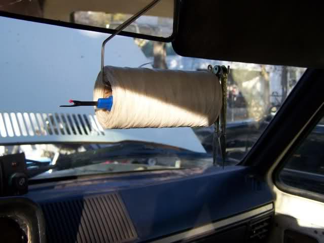
This is one of my favorite wiring tools now! Aviation wire tie tape! Its a freaking pain to do and I have MUCH MORE respect for the sadly underpaid aviation techs. Its difficult to do good ties in an area like this where its still relatively easy to get to everything.
A hour or so with that and taking time to reroute a few things got me here:
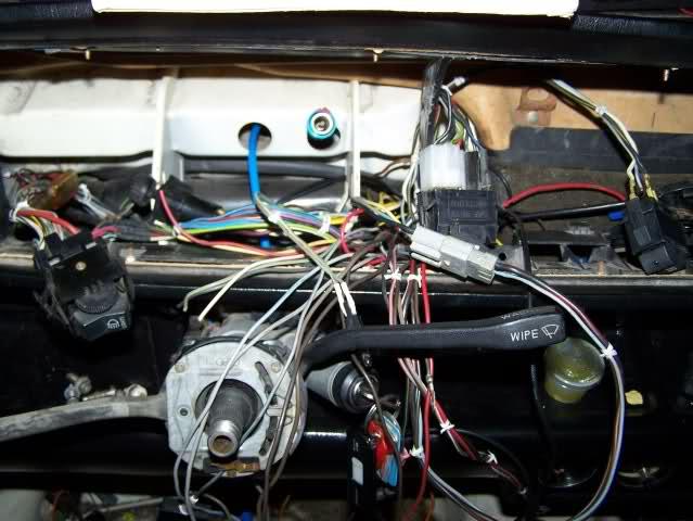
Still a small bundle of wires left snaking across the column switch assembly, but a zillion times better! Dan and I then went through and retested a bunch of the wires to see what was powering what up. Several things need sorting out and wired in a little better like the radio and lighter socket. So the above picture still isn't the final for sure.
Overall a VERY productive day I must say!
Only downfall was finding out that the fox is only seeing 2.7psi of boost, being able to hear the boost leak, but not being able to find anything actually wrong. The BOV seems a bit suspect, but it passes the operational tests with a mityvac...
December 11, 2009
Today gets a very big and depressing FAIL stamp across my forehead. So I have been meaning to modify all my instrument lights over to LED's. I finally got around to doing it. Working on it for the last few evenings while dinner is cooking.
First though I wanted to get my dimmer setup working. So I spent some time diagnosing why my crappy dimmer switch was so crappy and what readings I needed to have on it with a little help from some friends!
So lemme show the results.... First to modify a few of the bulb holders. Starting off by carefully pulling out the metal clips inside it. These tend to do damage to the circuit foils over time, so its nice to be able to eliminate this especially on the older foils like the '79ish one that's in this car. I used a 7/64ths bit, but that is fitted for the 18g wire. Smaller wire could really be used and then a smaller bit would be in order.
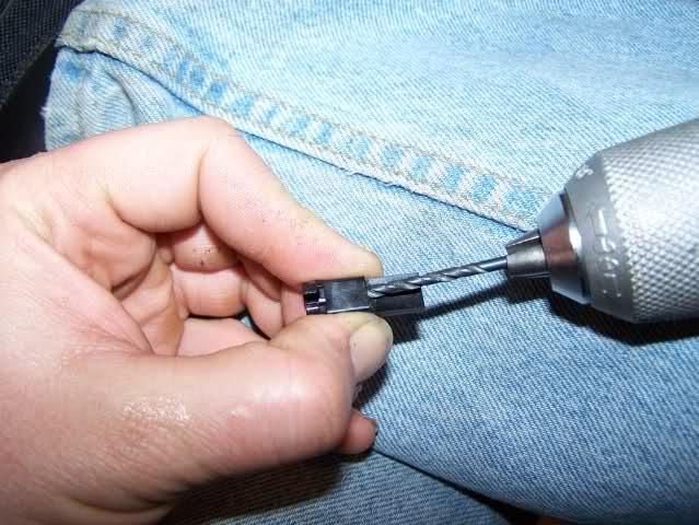
Of course be careful holding onto it like I did... Not the safest way but I didn't want to clamp the holder down in my vise and risk breaking another one.
Now setup the LED for running in a 12v environment. I bought a bunch of 470ohm 1/8 watt resistors a couple nights ago. We start off by attaching one to the positive lead of the LED, then soldering a wire onto it. I used 18gauge cause that's what I readily have on hand, way overkill!
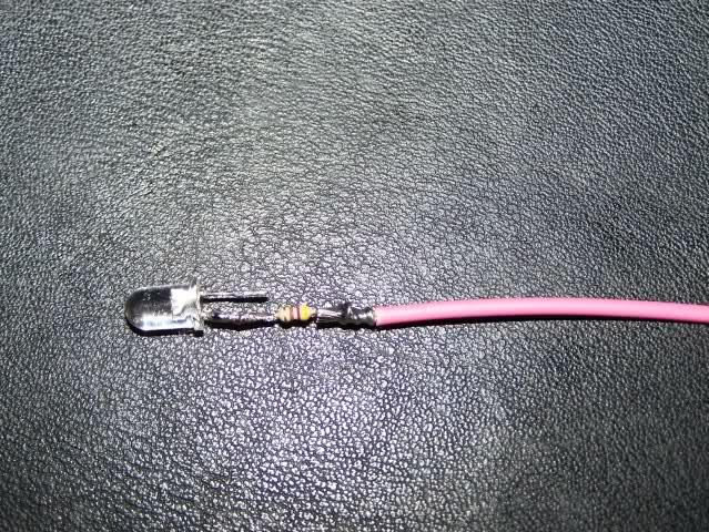
Then I heat shrink the resistor and next solder the negative side together.
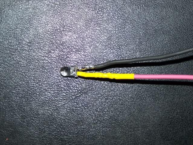
I then heat shrink that side together. Next I pulled the wires through the holder. I pulled the LED base as far in as it would go for support and stability. They could be left a little further out and the light pattern might be better. If I get bored I may experiment with this.
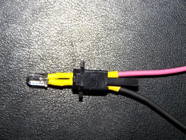
After that I then finished it off by adding a little more heat shrink to the outside to keep the LED at the height I set it.
Now they are ready to wire into the cluster. I soldered eyelets onto them and attached them to the light output going over to the speedometer bulb for the dimming positive side. The negative side I attached to a speedometer screw. When installed I plugged the grounding tab on the speedometer into one of my loose spade grounds on the harness so as not to ground and overload through the voltage stabilizer. Here they are attached to the instrument cluster.
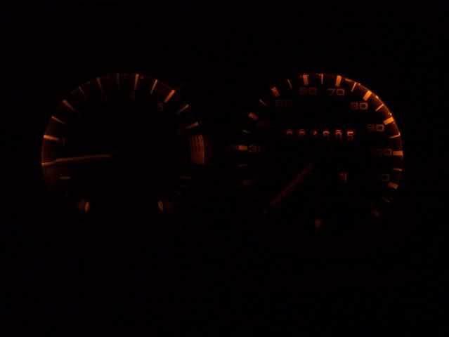
So now time for the critical test. I started off with some white LED's. First at the dimmest setting. For dim, these are pretty bright!
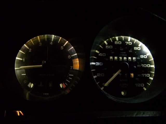
Then at the bright setting...
Yeah there is almost zero change. I took all the pictures with the camera's settings locked in to the same. I fiddled it to try and get the best representation of what I was actually seeing. Came pretty close too. Well not feeling that color. Its a "cold'Â white that has hints of blue in it. So I started again with a new set of yellow LED's. For the dim setting:
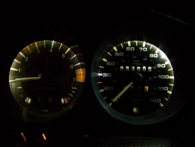
That color is spot on. Nice and warm. So for the bright setting:
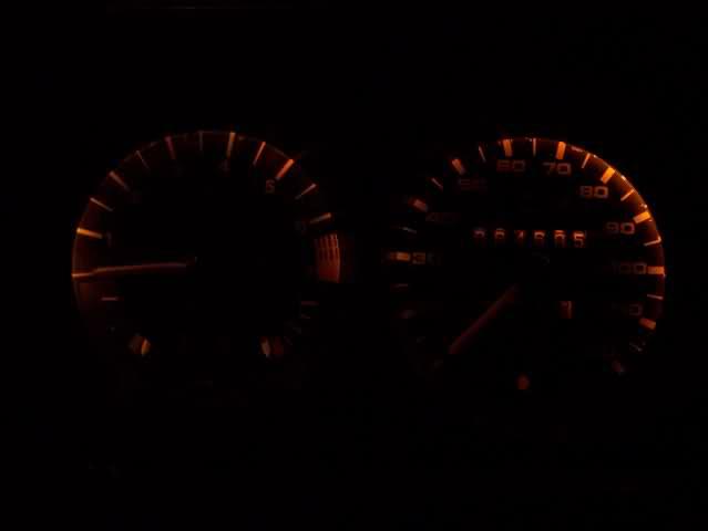
The yellow is super dim. Not cool. Okay I did default to the 470ohm resistors here too since that's what I had for the 1/8 watt babies. I should probably used about 320 ohm ones here, maybe 360 or so. The yellows have a lower minimum voltage too.
So... Not really liking the white, its super bright but not feeling the color. And the yellow is very dim. Not to mention almost zero dimming on both options. So for comparisons sake I put the regular bulbs back in. On dim:
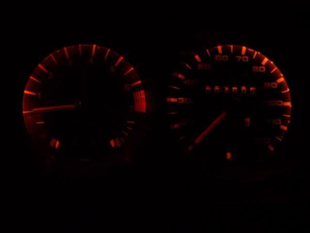
I couldn't get the color quite right. These look redder in the pictures than in person. And at the brightest setting:
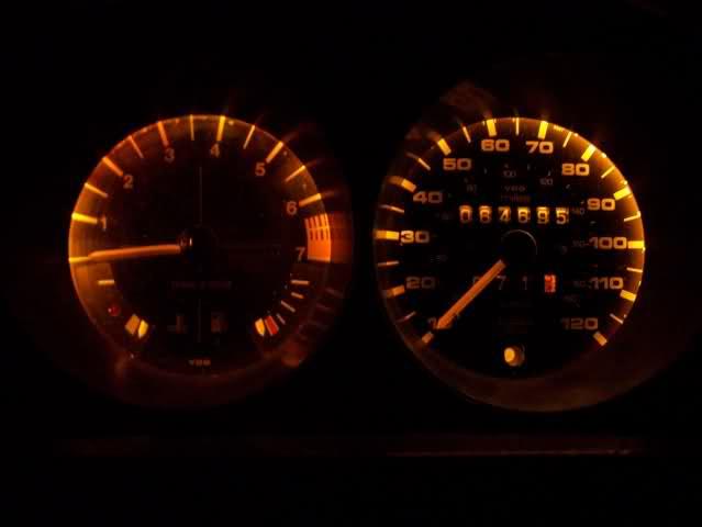
This is when I went back and looked at a few things. Still not getting a lot of dimming range, but these had a lot more than the LEDs did. Humm, back to the drawing board. So I test voltage change again. And not seeing any more change on my new test switch as I did on the old bad switch. As I think it over I realize that without everything hooked in, the resistance load across the whole circuit lowers causing less of a voltage drop. I hate Ohm's Law!
So I braved the cold and went out to Autozone and bought some bulbs to replace the radio light and a few others I had changed out a while back...
The whole reason to use the LEDs wasn't to lower the load on the circuit as much as to get bulletproof reliability into everything. I HATE changing these bulbs out all the time. Coilovers seems to kill them a little more often than I would like.
Well at least the whole theory behind it mean that using LEDs for the interior lights will make sense and put a lot less drain on the battery! I had started a couple days ago by modding these up to go into my glove box.
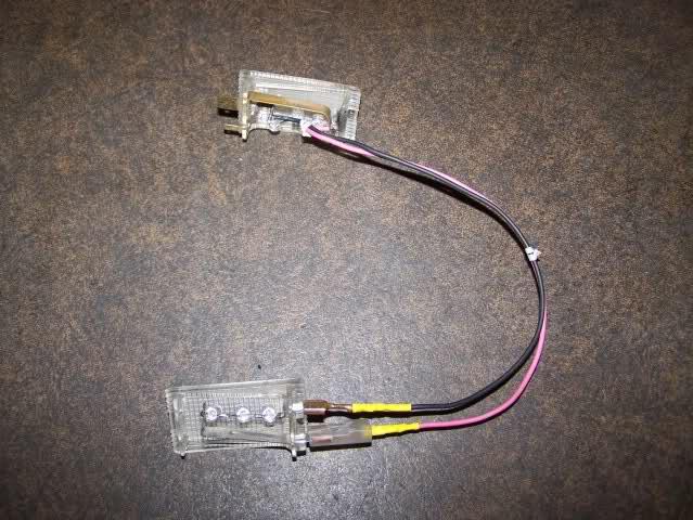
I am going to do my overhead and a couple under-dash/foot well lights up the same way. Using 3 LEDs in series seemed to be the best compromise for a safe voltage drop and not making them run hot. They still run warm, but 4 was a bit dimmer than I wanted. For the glove box that's not being used for long periods of time, this will work. For the rest of the lights that will be on for longer times, I think I will play it safe with maybe 3 parallel sets of 4 in series per assembly.
In the end, I am liking the incandescent OE bulbs functionality and color best for all the instrument lights. I also took my radio apart and figured out why it was doing strange things to the lighting. The small plug on the back I had originally thought was for the back lighting is bridged to the main power input. I am pondering cutting it from the bridge and wiring it up for the back lighting I thought it was for... To do it the way I feel is right though I need to build a simple circuit inside. The radio light turns on and off with the power switch. But wiring the back lighting in would mean its on whenever the parks are on. What I want is the radio completely off with the switch off, and the back lighting also off. With power on, I want the dimmer controlling the back lighting too. A small solid state relay, or a simple TIP121 transistor should cover me for this application though.
Maybe I will try out some red or blue LEDs. But I am not really feeling any of the colors so far. Perhaps green? Not sure. I like the original color a lot.