You must be logged in to rate content!
12 minute(s) of a 391 minute read
1-28-2010
All of the tables for Fuel, Spark, AFR Targets and a few other things in table format can be exported into whats called a .vex file format. This allows you to yank just tables out of a tune file, or .msq. To do this open the appropriate .msq. You do not need to be connected to the ECU if the file is saved offline.
Then go to whatever table it is you want to grab, and upper left corner select File/Table Export. I leave the first part of the default file name alone and dump the number portion for whatever car it is out of. The numbers are date and time the file was made. Useful too if you only are dealing with the one car.
I go through and save all the tables like this that I am using.
Now to be safe close down MegaTune and then reopen it with the file you want to put these tables into. Or just make sure to open the new file. Doesn't matter really....
In the new file you changing the .vex tables over go to the same place, say Spark/Spark Table 1/File/ but this time select Table Import. Select the appropriate table and ban there you go.
You can put the "wrong tables" in here. For instance your being lazy and want to have all you spark and fuel rpm and kpa bins matching. You could easily load a spark table into a fuel table. But your center section will have whacked numbers... I usually just manually fix KPA and RPM bins instead.
Another cool tool to not only grab maps out but to load them into other sections is to go to the Tools/Review Mode and start running through all your .msq pages. For instance when you get to VE table 1, export it. Eventually table 2 and 3 come up and you can quickly import matching tables into these spots to have a quicker starting point.
But there is one place that due to software and different settings between computers I frequently see problems where doing the table export/import becomes very important.
For some reason the way AFR target tables are saved and translated gets easily confused. If I send somebody an .msq made off my computer that's setup for the LC-1 Innovate wideband sensor, and their computer is setup wrong for narrowband, or even a different wideband sensor, when they load the .msq up the tables can end up in volts and backwards, or just way off.
The fix is easy though most times. In this case we go into configurator, set it for LC-1, accept changes, load MegaTune. Make sure the AFR table looks normal now, then export it. Close MegaTune and reopen Configurator, set the correct wideband, close, accept, open MegaTune. Go into AFR Targets, Import the table you just exported, save .msq. Shut MegaTune down, reopen, reopen the ,msq, and make sure the table is now reading correctly.
When tuning and processing datalogs its VERY IMPORTANT to have all the oxygen sensor settings correct in the ECU, in MegaTune, and in MegaLog Viewer. MegaTune "software" settings are all setup via Configurator. ECU settings are via MegaTune. Be careful to have the sensor type set correctly. And I never tune with the oxygen sensor having any authority enabled. It can mask problems enough to be more of a problem than a help. If I have a new car without any fuel maps, I will level everything and then give the sensor maybe 50% to get a very rough map. The car will run horrible for the first two runs. I then dial it down to 20%, then usually turn it off. Only "maybe" turning it back on after the car is fully dialed in.
February 21, 2010
There was a LOT more to the story it turns out. I rarely take a customers word for what a specific component is, like say the size of the installed injectors. But in this case I had grabbed the numbers off the injectors and couldn't find anything. So I had my buddy verify what size they are. He swore up and down that they were 450cc injectors.
So the MegaSquirt was programed accordingly. To almost disastrous results... I kept adding fuel trying to get warmup and starting dialed in. Finally got it going after putting more than double the "normal" amounts into it. The car was smoking badly but I had a decent idle and cold cranking finally. The car warmed up and was sitting at 190 running beautifully. So I went for a short drive. About a block away the temperature suddenly climbed to 220 and then problems hit. There was so much fuel in warmup that at 190 it was still adding fuel it seems. At 220 it wasn't and the engine went dangerously lean. by the time I got the car back to the house I had flames coming out of the shifter boot.
So I had a while to process everything while cooling the car off with a hose and decided to check the injector numbers again. This time I got lots of hits on them. Turns out they were 240cc injectors and NOT 450cc ones.
And the other odd issues were being caused by the fact that the Toyota fuel pump can't reliably deliver more than about 50psi. So I can't compensate by turning the fuel pressures up enough.
So looking around for performance calculators and trying to figure out a couple more details on this I stumbled across this gem of information.
Air/Fuel Ratio Limits
6.0:1 Rich run limit
9.0:1 Low power, black smoke
11.5:1 Rich best torque at WOT
12.5:1 Safe best power at WOT
13.2:1 Lean best torque at WOT
14.7:1 Chemically ideal
15.5:1 Lean light load, part throttle
16.2:1 Best economy, part throttle
18-22:1 Lean run limit
I found this and some really good calculators here: http://www.stealth316.com/2-air-fuel-flow.htm
In bunny news, I lost my brakes. Specifically the master cylinder took a crap on me. It had been acting up a little bit the week leading up to it so it was not a complete surprise. Time to overhaul my setup. Last night I got the new MC painted up, and a spare. I am hoping to get it on later today!
March 01, 2010
Crap... So my basket is not a THULE one like I thought but actually a Yakima. Only badging on it was "Subaru" on the fairing. Well the Subaru has been gently rubbed off with Ajax and replace with proper (or imporper I guess) THULE sticker.
I am NOT a fan of Yakima, but I like the way this basket looks so I will live with it since I can't complain about how much it cost me.
Hopefully I will get caught up on all my projects tomorrow so I can get back to installing my alarm. I am damn tired of fumbling with keys in the dark.
March 07, 2010
Today we had an adventure in alarm testing. I am tired of not having power door locks. So I got out all the goodies and decided to figure out how to wire it all up. The problem was my lock control unit has no markings as to what it is and hence I can't find any wiring information.
I am using a Jaguar door lock actuator since it also has internal switches to activate the locks. After about 2hrs of fiddling with everything, I now have door locks that lock and unlock with the alarm, and with pulling or pushing the lock pin on the door!
At the moment nothing is actually wired into the car, and in fact I stole the car battery to power it all for testing. Its sprawled out over my living room floor looking like somebody murdered a couple wiring harnesses.
I think I want to setup a trunk release for the hatch. I should be able to get an actuator to pop the hatch, but I am not sure yet. Also not sure if I want a door switch actuator on the passenger side too. My second actuator/switch combo one seems to be missing at the moment, so that may make up my mind for me.
Well we shall see! I made LOTS of progress today on it! Once I sort out mounting locations for everything, I am ready to put it all in permanently. Already have the door lock actuator mounting all sorted out and lock rods made up.
March 27, 2010
We should see some serious progress on her this weekend! The weather has mostly turned for the better. I am about to go get cracking on her and see what I can get sorted out. I am hoping to accomplish a few key key things today.
First I need to get my headlights properly relayed. Also I want to get both speeds on my fan working and then start cleaning and heat shrinking the remaining OE engine bay wiring. I should be able to have that all wrapped up tonight or tomorrow.
At the moment I am not sure what course of action and control I want to take on the second fan speed... The wire is not available in the plug to just wire it that way. I may decide to control one of the speeds via the MegaSquirt so that I can change the kick in and out temps.
If I decide on the MegaSquirt control, then I think I will use that on the low speed where programming it is most likely to make a noticeable and usable difference. I can also use this to kick the fan on in a few other operation conditions....
March 28, 2010
Wantacad was asking me for some sensor placement information, specifically the placement of the OE gauge sensor in my setup Its not very clear from the other pictures in here as to what I did and where it is, so here is a good picture of it.
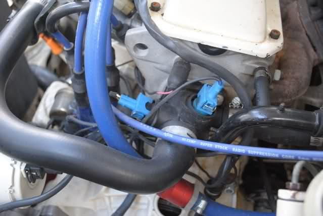
The right blue sensor is for the MS and the left black one is for the coolant gauge.
Yes I am using the OE Bosch sensors. Its MUCH easier and way more accurate to use the GM sensors though. How so? Setting up the GM sensors only requires basic hardware modding. While running the Bosch ones requires modding the ECU slightly, modding the internal code, and some basic file hacks. While its fairly easily accomplished with Easy Therm, I still find most people have much more trouble with this than with modding the car for the GM sensors. Did I mention that the GM sensors are MUCH more accurate?
Why did I use Bosch then? I had a harness on hand already built for the Bosch sensors and didn't have any spare GM sensors in my inventory. And I have modded the code so many times I can do it in my sleep!
So to use the GM sensors with these black plastic water outlets all you need is a simple adapter. They are sold on here for about $25 made out of aluminum. But I found a much better way to make them that satisfies my 'Must have it NOWâ€Â dilemma I usually have. You start off with one of the VW block off plugs. Some of the time a new water outlet comes with one. Otherwise they are only $2 from the dealership.
1)Flip it over and carefully center punch the very center of the bottom.
2)Starting off with a small drill bit, drill through it. You should be able to keep the drill going through the very center of the reinforcing cross hairs on the top side.
3)Slowly go up in bit size to keep it centered.
4)Once you drill out the center to the edges you need to grab a 3/8ths NPT tap.
5)Tap it slowly, it is a pain to start. Beveling the edge slightly will help.
6)Once your going slowly tap and test it. You can get the GM sensor to screw down flush with the top of the block off plug.
The IAT sensor will require either pulling the intake manifold and tapping it, or to find the metric GM sensor that screws into the Bosch hole. They do exist. Its for a Saturn or something.
As for the gauge wiring, I used a two wire ABA type sensor. The early gauges only use one wire. But the resistance curve is the same. The other is simply a ground. The older sensors are grounded through the head. Since I made the whole harness for the engine, I simply ran the ground for the newer style coolant sensor into the harness and the signal out to the gauge.
Not sure how accurate my gauge is compared to the original setup, but I ignore it most of the time anyways. Its a decent reference not much more. My CEL I programed to monitor water and intake temperatures. It goes one color for water temp warning and another for IAT temp warnings. Since its programmable through the MS, its easy to adjust. Also most of the time if I need to monitor temps I am doing so in MegaTune.