You must be logged in to rate content!
10 minute(s) of a 97 minute read
9-13-2015
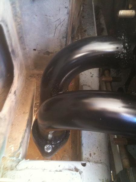
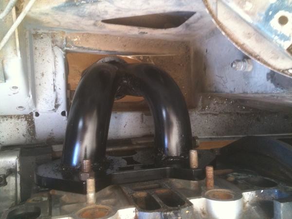
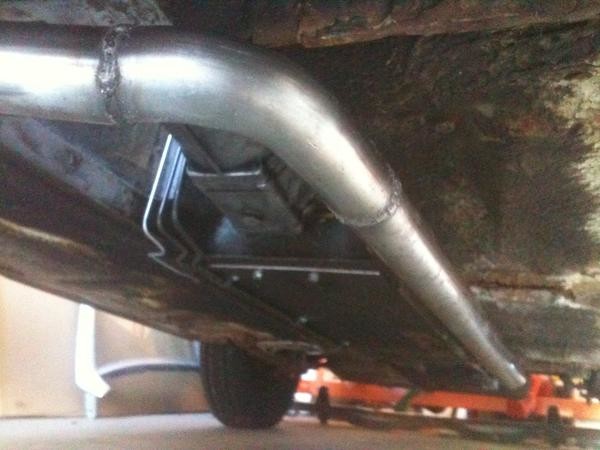
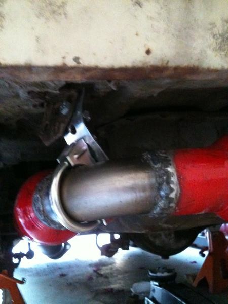
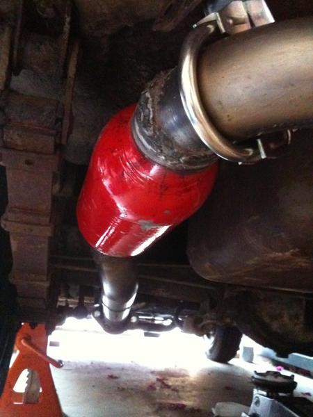
So, six months since my last post. I am now posting in big batches, rather than every last thing as it happens. We left off at the header fabrication. I cheated by using pre-made flanges and a collector from Racing Beat, along with some pre-bent pieces. All 2" outside diameter, .120 wall steel, the thick and heavy stuff. I routed the exit down through the factory hole (without trimming) between the right side frame rail and the fender inner panel. Then under the car, laterally across the back of the oil pan, to the driver's side, then straight back and under the rear axle, approximating the factory routing in that area. At this time, I am using an air gap around the pipe for insulation from the rest of the car. We will see how that works. The lateral piece is the low point on the car, and protects everything behind it (I hope). As the pipe is essentially 2 inch roll bar material, the rest of the car should bend before it does.
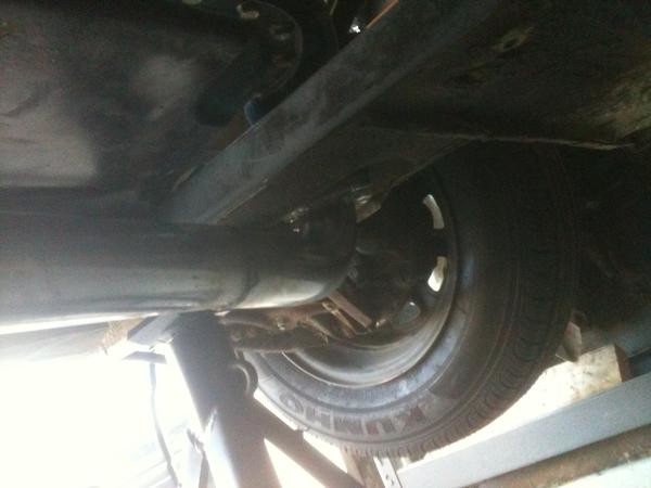
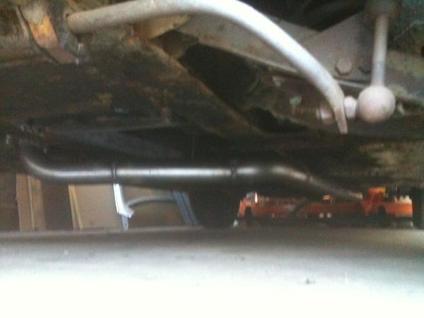
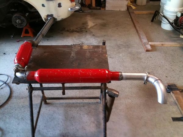
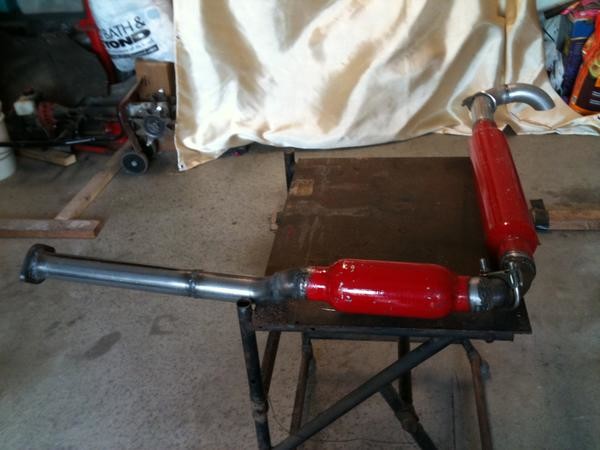
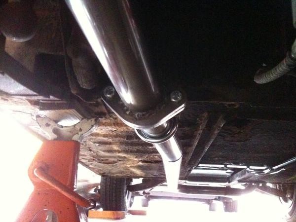
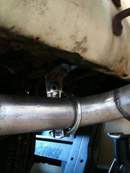
Attached is another photo, showing the relationship between the tailpipe where it turns to the rear of the car just forward of the transmission, the transmission rear mount, and the fuel, fuel return, and rear brake lines as they go up to the heater mounting panel. Meanwhile, the mufflers are being assembled out of 2" diameter Cherry Bombs, a short one on the left side, and a long one under the back of the car. There is a kick-up aft of the rear axle and before the short muffler. The pipe is flanged just aft of the factory bracket mounting location on the panel aft of the driver's seat. The last photo shows the flange and the mount, as well as the route that the pipe takes after leaving the header.
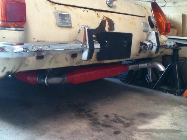
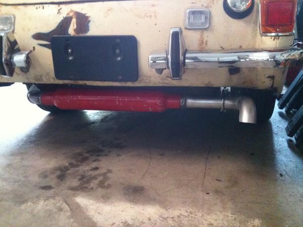
We will see if the Cherry Bombs are quiet enough, or if they hold up. The shells are rather thin, but they can be cut open and refilled with steel wool or lava rocks (thanks for the hint in your post, Hap), if they start out ok and get louder over time. The pipe shows a turn down at the end, to keep the noise down. The last piece from the second muffler is actually thin wall aluminized steel, which will cool down much more quickly than the rest of the system, as the exit is near the fuel filler.
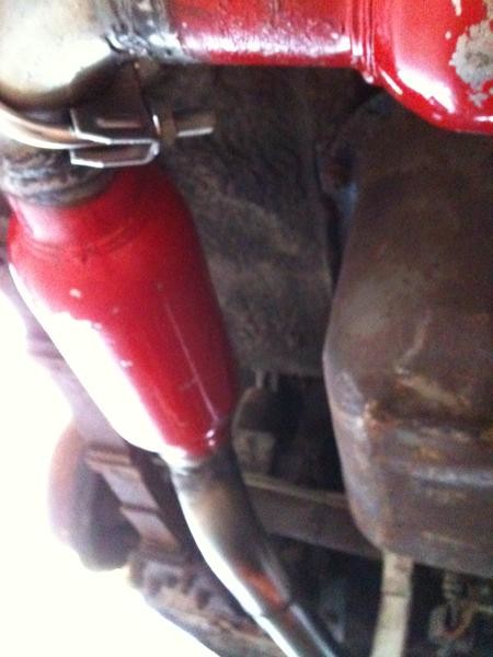
I am using an air buffer around the fuel tank, rather than panels or other materials. We will see how that works. Also, I am using heavy duty clamps at the factory mounting points in the aft part of the car. Photos on the next couple of postings.
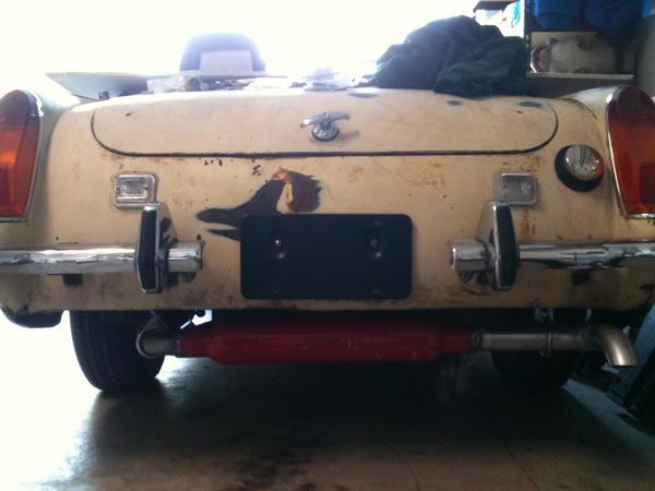
Here are the clamps on the left side and right side of the rear of the car. Also the relationship of the assembly to the back of the car. It all hangs down a bit. That is, in part, to get lots of air circulation around the pipe.
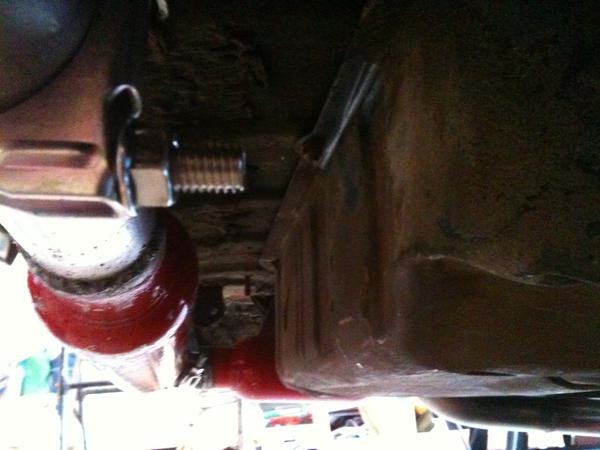
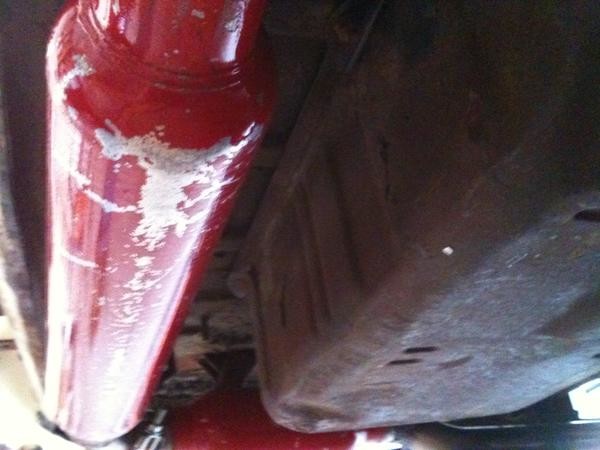
Now to show the gaps between the exhaust system and the fuel tank.
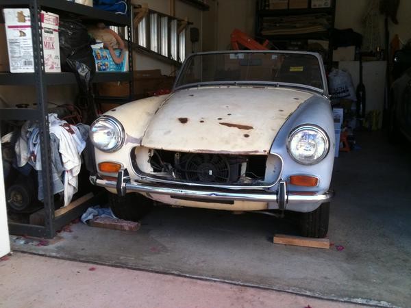
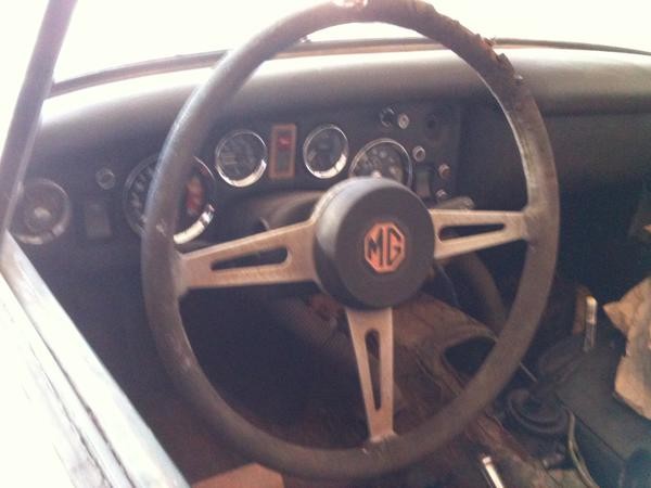
So the car is coming along! The back, the front, and the dashboard (which is mostly done, but the steering wheel still needs some work). You can see the set-back of the shifter. We will see if it works without going into alternate tailshaft assemblies, and just using the RX7 piece as-is.
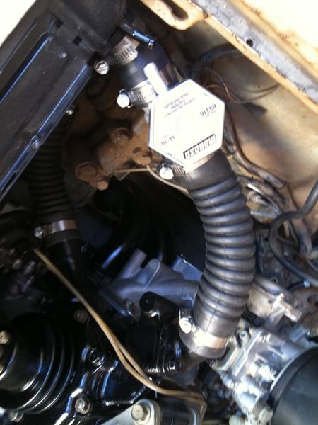
Now to the engine room. The cooling system has been the big hang-up here. The Audi radiator outlets are 1 1/4" O.D. and the Mazda water pump outlets are 1 1/2" O.D. Moroso makes a cool little cast piece (photo 1) which has the radiator cap, the overflow outlet, 1 1/4" on one side, and 1 1/2" on the other (got it from Summit). I will dummy cap the outlet from the top of the radiator. This arrangement also means I do not need a pressurized overflow tank, which I would have needed if I used the radiator overflow outlet.
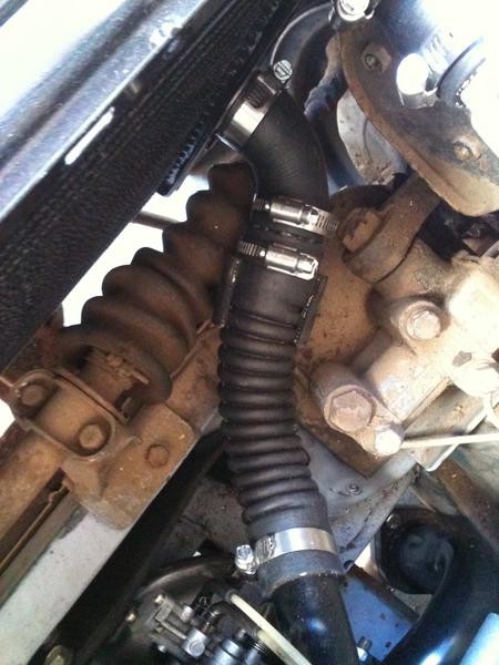
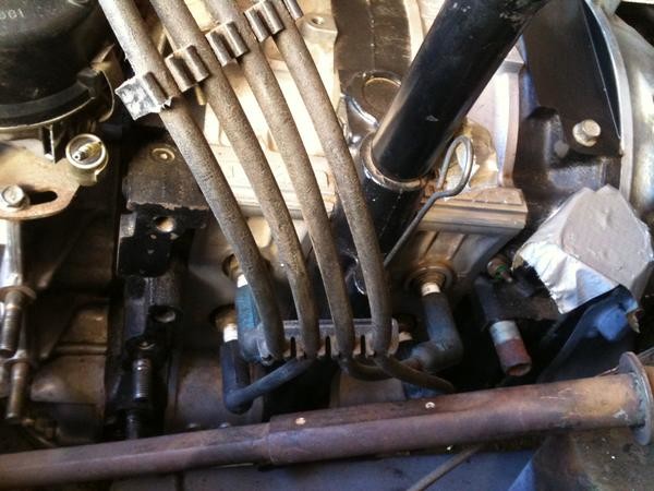
Photo 2 shows the lower hose, also 2 pieces. I found a trick little 1 3/8" to 1 5/8" steel exhaust pipe piece. I cut off the ends and used it as an adapter (Summit, again). The hose clears the steering and the lever shock just fine, and I did not need to modify either the radiator outlets or the water pump outlets to make this work. It does rub a bit on the lever shock mount, along the turned-up edge of the mounting plate. I wrapped a spare piece of radiator hose around the area. You might be able to make it out in the photo, or maybe not.
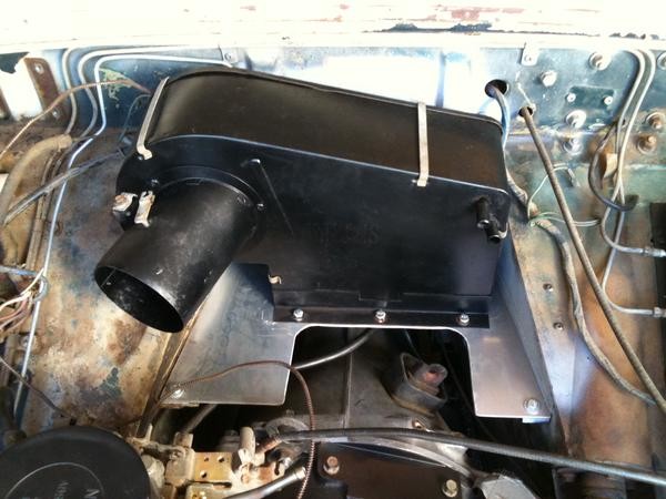
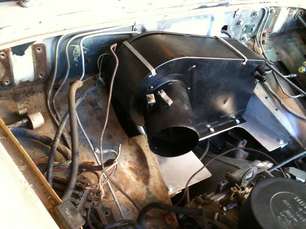
I decided to go with the '73 heater core, as I had it already and it is in good shape. In moving it back on the heater tray, where the battery used to go, I had to notch the passenger side footwell roof. Other than that, it fits just fine, and leaves room for the fuel lines behind it (photos 3 and 4). I like to keep as much of the factory Mazda and factory MG as possible, just to make the marriage interesting.
The inlet and outlet on the '73 heater are perfect for the application, as both the engine and the radiator outlets for this system are on the left side of the car. With this arrangement, there is also maximum room on the passenger side footwell roof for fuse boxes, relays, and voltage regulators (all to come later). You can also see where the clutch slave cylinder will mount up, solving one of the biggest Midget nightmares, bleeding the darn clutch.
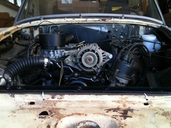
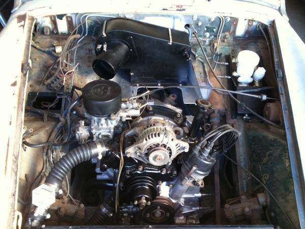
Engine room clearances. In photo 1, from left to right, we see the upper radiator hose, the carburetor, the alternator, and the distributor. Alternator (with the factory fan belt and factory bracket) and the taller electronic distributor did not clear the hood too well, the spark plug wires got crushed a bit, and the alternator just flat out banged the hood (but it was close, it almost made it). I am using the older points distributor, shown here, as it has a shorter cap than the electronic piece. This way we get a fair amount of clearance. For the alternator, we will go with a fan belt one size shorter than stock, and shorten the adjustable metal bracket, and we should be good to go.
Photo 2 shows the spark plug wires, and the old style factory ends that connect at diagonals to the spark plugs work perfectly. Now this set is about 40 years old, so we need to source new ones. I am also looking for diagonal spark plug ends and 90 degree distributor cap ends.
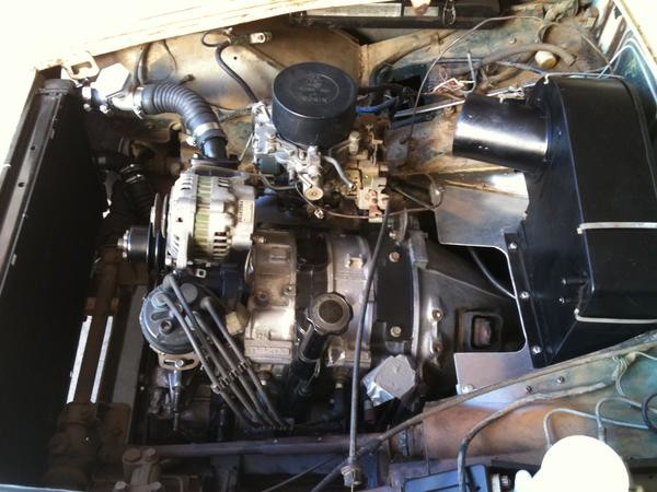
Photos 3 and 4 give a basic overview of the engine room as it sits now. There are a bunch of small things to do, and one big one. There are the fan belt and alternator bracket assembly, the fuel lines, the throttle and choke, the oil filter and oil cooler assemblies, the driveshaft, the radiator overflow tank, the battery, the heater lines, the brake hydraulics, the clutch hydraulics, the air cleaner assembly, and...
The wiring. The electricals are the big job now, from the coils and ballast resistors (2 of each), which will mount on the left side inner fenderwell, to the fuses, the relays, the alternator and voltage regulator, and the integration of the Mazda engine room wiring to the MG rest-of-the-car wiring. I am going to try to keep all the Mazda and MG wire color codes and connectors as stock, and I do get to eliminate some Mazda engine room solenoids, relays, air valves, and all the wiring and control boxes that go with them.
Kevin, I looked at those, but gagged on the price. I will see how these go first, as the basic dimensions and the flow through process are the same, it is only the packing material and the heavier gauge metal housing that are different. If these are too loud at the outset, the RB part probably will be, too. I used something similar from Rotary Engineering a long, long time ago (with stainless steel wool instead of fiberglass, that is the basic difference here), and it actually worked well, mated with a second muffler downstream. The lack of race porting should keep things a bit quieter as well. This is a sort of a test bed, we shall see how it works out.