You must be logged in to rate content!
14 minute(s) of a 97 minute read
7-20-2016
It runs!
Did the tried and true "hook everything up and give it a shot" method, and it worked. Must have gotten the electrical system done right, and guessed mostly right (by eye) on points and timing. It is a bit loud with the Cherry Bombs, but liveable. No brakes, drive shaft, or throttle/choke/clutch linkages or air cleaner assembly yet. Going to try to adapt the factory late model 1500 choke and throttle, since the carb on the later Triumph engine sits on the right side of the car, like the Mazda.
Is the cooling sufficient? Will the rear axles break? What's it like to drive? Stay tuned. I will also report thread sizes and exact adaptor requirements for engine sender fittings to the MG gauges.
Here are the weights (fuel tank 1/2 full): 1633 lb without driver, 1813 with driver. Rear weight 48.8% without driver, 51.4% with driver. Left side weight 50.3% without driver, 52.9% with driver. This is with a full size battery mounted in the right side of the trunk.
9-27-2016
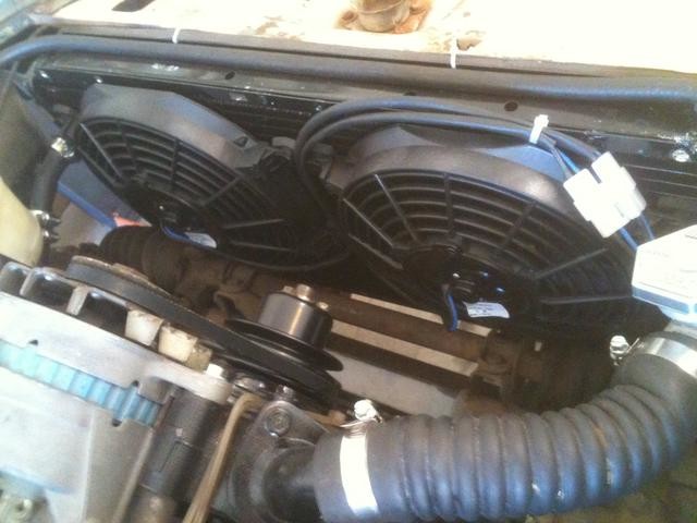
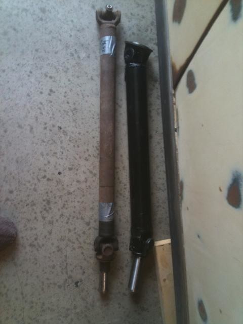
So here is the second to last (knock wood) series of entries. Everything is just about done except for installing the new driveshaft, finishing the brakes and parking brake, and getting some wiring glitches in the brake lights, wipers, and headlights worked out. None of these items are central to the engine project, but they must be done before any test drives, at least the brake issues. Decided to bypass the fan relay and have them on anytime the key is on accessory or ignition, so I do not forget to turn them on someday. Fused, but no relay. Also, I substituted some aftermarket Summit cooling fans for the M-B pieces, which I was struggling with--one of them had electrical issues, and they drew lots of amps.
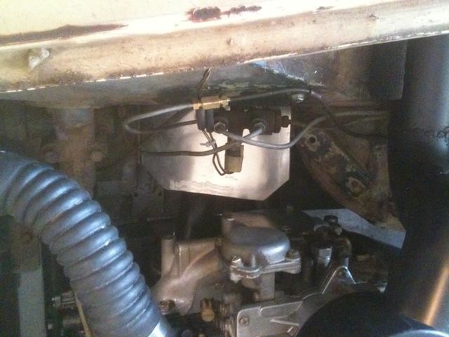
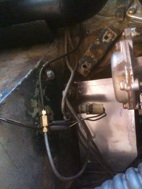
Built an aluminum (.080" 5052) heat shield to go between the hot exhaust and the brake proportioning valve and lines. We'll see how it works.
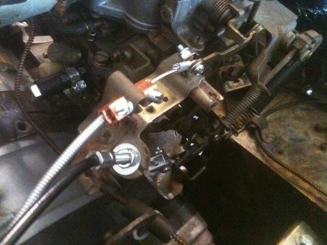
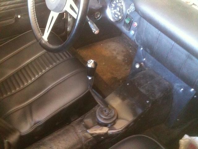
The MG Midget 1500 throttle cable and clutch cable worked just fine. Shortened the end of the clutch cable sleeve by a couple of inches, which gave me more choke cable end to work with. Made up ends that worked with the Mazda carb brackets, using Home Depot bits including 1/16" aluminum ferrules to make cable loops. Factory mounts at the left side footwell roof for the throttle and the dashboard for the choke.
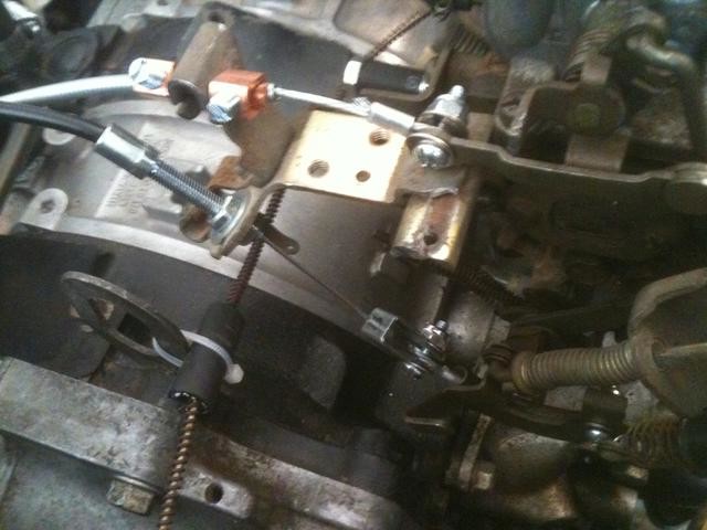
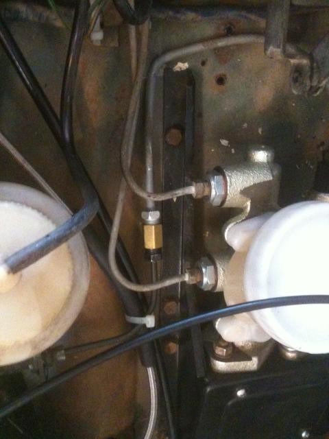
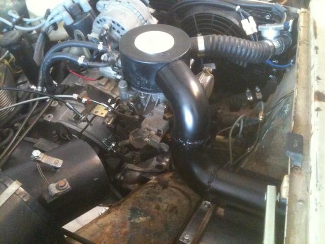
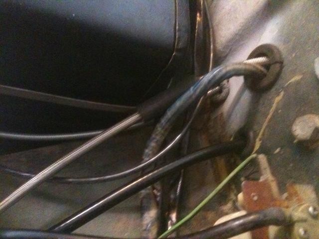
Note the weird spring and rod assembly on the right side of the first photo. That is a factory Mazda installation, done to automatically close the throttle if the throttle spring breaks. The throttle spring pre-loads the hinged piece at the top right, and if the pre-load is lost, then the spring straddling the rod is released, slamming the throttle shut. A fail-safe, as the rotary will quickly spool up to oblivion if the throttle return spring is lost. A clever little deal.
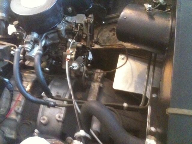
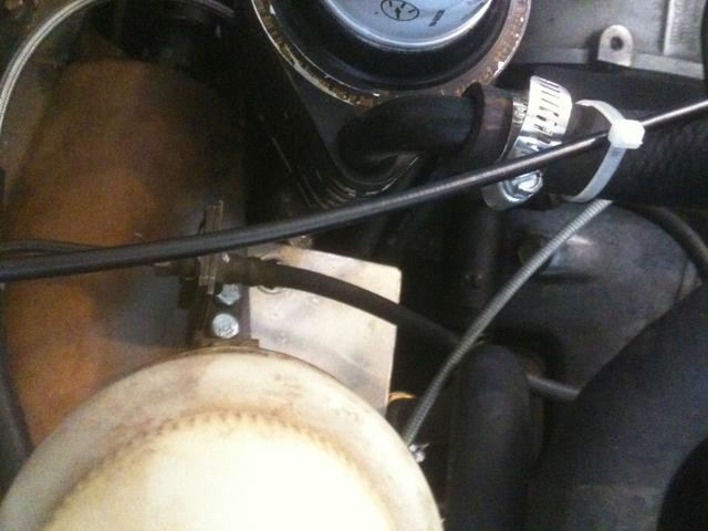
Fuel lines. 5/16" from the fuel pump (Facet electric in the stock location out back) under the car to the carburetor. 1/4" return line from the carburetor back to the factory hard return line, on the bulkhead just forward of the rear axle. Mazda uses a system where the fuel is in full flow from the fuel pump at all times, and recirculates much of it back to the fuel tank if the car is at idle or at low speed. I believe this is done to minimize the time in which the fuel sits in the hot engine room in those fuel lines, to reduce the possibility of vapor lock. The lines come vertical from the bottom of the car on the right side of the bell housing and up behind the heater box. Then they turn right and wrap around the heater box, and up the center line of the engine to the flex lines. This keeps them as far away from the hot exhaust as possible.
No charcoal canisters or anything in that return line, the factory MG one in the right rear fenderwell is removed and bypassed. For some reason, MG ran that fuel return line all the way back to the right rear corner of the car before it turned up from under the floorpan into the trunk area. I do not understand this arrangement, as the line seems very vulnerable. Hard to detect in my photo, but the hard line was cut and a small piece of flex line was used in that back corner (the hard line had been pinched right there), but it is awfully close to the hot exhaust pipe. Rather than heat shield it, I will reroute that line to enter the trunk area just aft of the wheel well, well before the rear corner of the car. It's on the final list.

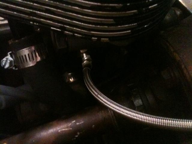
Clutch line. Used the MG piece on the master cylinder end, and the Mazda piece on the slave cylinder end, with a FedHill type connector and adaptor. Works great, the clutch pedal pressure is a bit heavier than the MG factory set-up, but bleeding is a breeze. Mounted the factory Mazda bracket hard-line-to-flex-line on the top of the left side footwell.
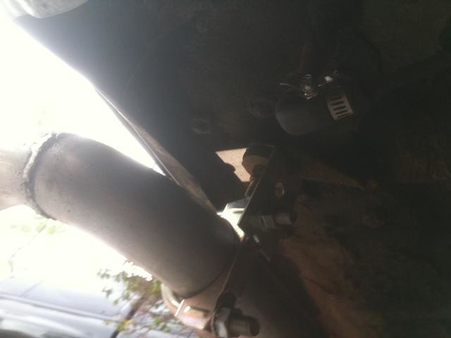
Brake lines. Using the factory brakes, but the rear brake line needed to be routed under the car, and not through the transmission tunnel (no room in there, the Mazda transmission is a tight fit, though there is no cutting except for the shifter location and the heater tray cutting.
The new brake line runs from the right side fenderwell, above the proportioning valve, and back to the firewall, around the corner of the heater box, and down the right side of the bellhousing, then under the car. It is bundled with the fuel line and fuel return line down the strengthening channel for the right side seat, and away from the exhaust pipe running down the left side.
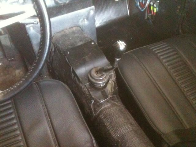
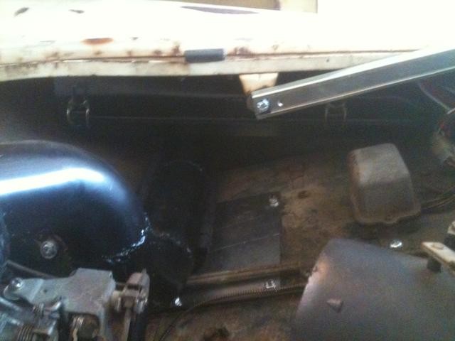
The shifter is further back than factory, and it has that bend in the lever, but it is not too bad. If the seat were moved up, then it would probably be a bit of an issue. The cover is in two pieces, with close clearances. Four machine screws in the outer corners hold them down. When the soft shift gaiter cover is added, additional screws closer to the shift lever will help hold the panels down. This close clearance is possible only because the drivetrain is almost solidly mounted (more on that later).
Incidentally, I found that for us long legged people, if you put the back of the seat frame on the floor (no rails) and elevate the front, it makes it very comfortable. The front of the seat bottom is in approximately the stock height (kind of close to the bottom of that factory steering wheel), but the angle of the seat bottom gives great support to the thighs and makes sitting in that tight spot very comfortable.
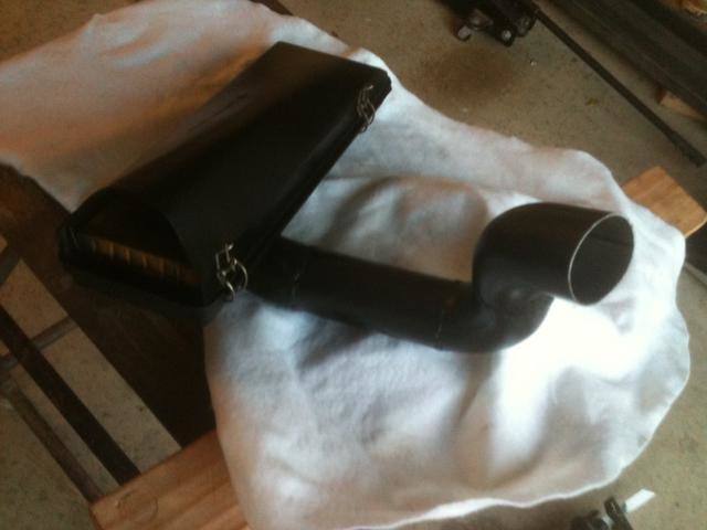
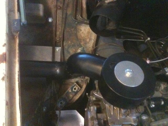
Air cleaner. It is a slip fit into the plastic piece on top of the carburetor, and snakes over to the Jaguar XJS V-12 sourced air cleaner box. The air cleaner box sits well out of the way under the fender top, and easily clears the bonnet support rod. The assembly is supported by a thick piece of rollbar padding, and sits crosswise right in the valley where the footwell and the fenderwell meet. If this were a racecar, the tubing diameter (2 1/2" aluminized steel) would probably be insufficient. For driving around on the street, it should be just fine. This ended up being a bit of a trial-and-error experience, with a couple of false starts when it came time to go from concept to actuality. I am hoping the gravity and slip-fit will suffice. Again, a solidly mounted engine helps things along, but you still need some flex and give in the assembly, and I hope we have the right amount of it here.
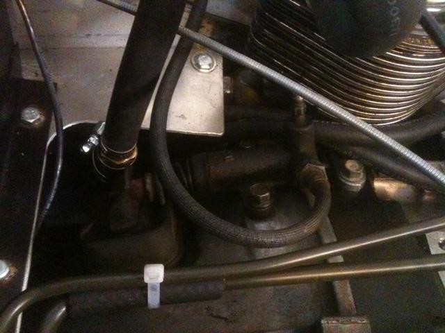
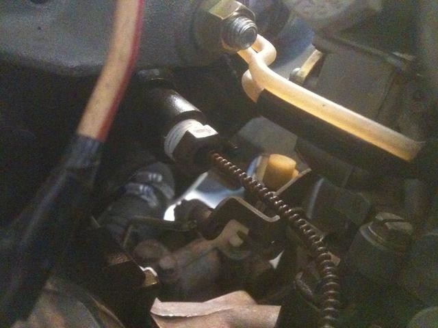
Oil pressure and coolant temperature gauge lines. Used the factory gauge and the coolant flex line with the bulb on the end. The factory Midget (1275) set-up, with the extra pieces and sleeves at the engine end, fits into the Mazda thermostat housing exactly. Tried to route the line away from the hot exhaust, and out of the throttle linkage.
For the oil line, used a braided line with -3 ends on both sides, with a British adaptor on the gauge end and a metric adaptor at the engine end. The engine take-off is right under the oil filter on the left rear, perfect for a short line to the dashboard. All works great.
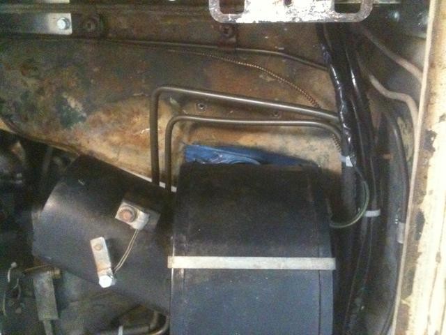
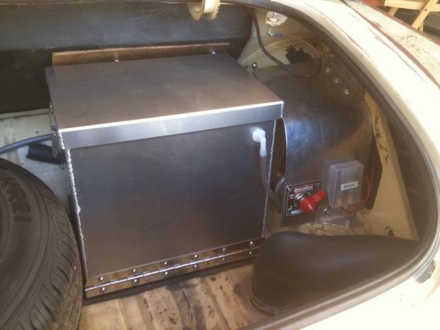
Back to the trunk. The battery box, if you recall, is a nice stainless steel piece (Summit), but must be tilted for the battery to be added or removed from the box. A frame was built, bolted to the right side trunk floor. A piano hinge, and the box. Works nicely.
There is a pin on the left rear of the box, note the small extension on the frame to accomodate a bracket that holds the pin. This keeps the box from tilting unless you want it to. Not race car solid for the big crunches, but should work fine for the street.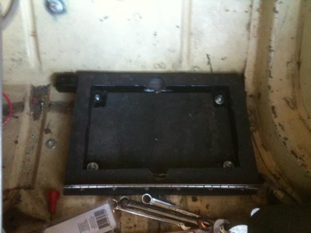

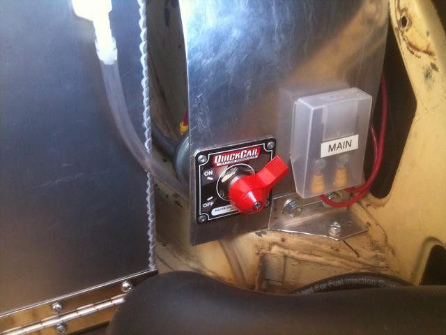
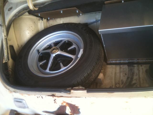
Now for the rest of the trunk, on the right side you see a master switch and the main fuse for the car (70 amp, with an 80 amp standing by as a spare). With a locking trunk, these are out of reach for hot-wiring. On the left side, the stock spare fits exactly (fraction of an inch to an inch-and-a-half to spare on all sides). It rests on the left side frame rail and an "X" made out of 2x3 pine (actually 1 1/2" by 2 1/2", as wood comes smaller than the stated number). No plans to actively fasten down the spare at this time, or further embellish the stand. The stock jack and little lug wrench fit nicely under there. And you end up with room for a small duffel bag and a couple of lawn chairs...
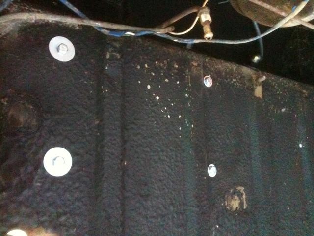
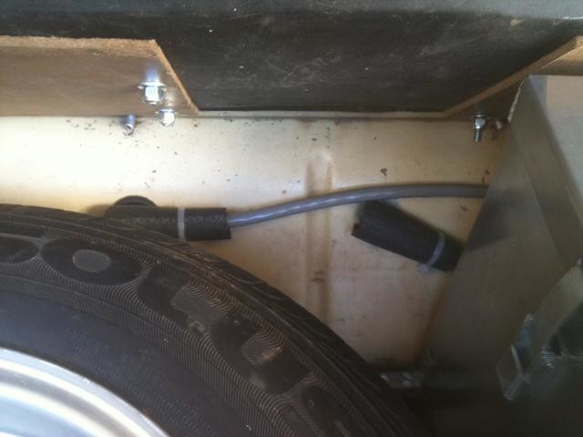
Behind the right side of the spare, to the left of the battery box, the starter cable is on the left (mounted to a bulkhead fitting passing through to under the car) and the ground wire from the battery on the right. Both are wrapped in heater hose for insulation and tie-wrapped up, Saturday night race car technology right there.
By not fabricating an oil pan, and using the stock Mazda piece, it turned out that the engine and transmission were essentially solidly mounted to the car (very close oil pan clearance). As it turned out, the factory (1984-85) 12A engine, and its integral oil-water intercooler and factory carburetion fit the engine room exactly, as does the transmission. The bell housing has some issues on the top side, but the starter, too, fits really nicely, and the factory transmission crossmember can be kept.
As the rotary has very little of the VH portion of the NVH, we can probably get away with it. This makes exhaust pipe mounting and anything that goes from the car to the engine much easier to deal with. You still need some flex in the systems, but not much. We'll see how it works in the real world. These engines are noisy and generate a lot of engine room and exhaust pipe heat, so we will see what it is like to live with that in a street car. My "bench racing" impression is that the perkiness of the powerplant will be great, and should not quite overwhelm the stock chassis set-up. Will the factory rear axle hold, with skinny tires and a low-torque engine? I think some of the "soul" of the British car will be lost in doing this, which is why I used a real beater MG for the project, and would not recommend anyone use a "nice" car for something like this.
I would do many things very differently in a "race", "track day" or "autocross" car. This one is strictly a daily driver street car, with the idea that it does not race around, but just enjoys driving to the store or wherever it is people go, especially on weekends.
Back to "bench racing" this thing. On paper, I think the attractiveness will be for the rotary engine fan more than the LBC fan, as this application should show off these little engines very well. The factory cars were always a bit heavy for the engines in the early 12A cars, and the pollution controls and Japanese style electronic gymcrackery always muddied up a very simple and straightforward engine. These engines have a behavior and response all their own, and I think a street car that is not trying to be a musclebound race car will show off the engine's charms very well. Stay tuned. The goal is the San Diego British Car Day in two weeks, we'll see if we get there, and how things go.