You must be logged in to rate content!
11 minute(s) of a 668 minute read
2-16-2012
Your concern is exactly what my concern is. I went back and forth deciding whether to use aluminum or stainless, I decided on stainless for it's facial strength.
What I mean is.... if there is shrinkage, then there will be vibration. If there is vibration, I figure the aluminum will be more sensative to having material rubbed away making the situation worse.
I tried to make the spacers in a way that they will have as much surface contact to spread the pressure around evenly.
Yup, this is one of those situations where you're down to your last resort, make your best judgement call and move forward.
I'll be the first to admit I hate breakdowns and failures. But I'll also be the first to admit, if I didn't take a chance, or step out of the box once in a while, I'd never advance in my fabrications.
Just be prepared to learn from a failure, it's easier to get back on the horse and move forward.
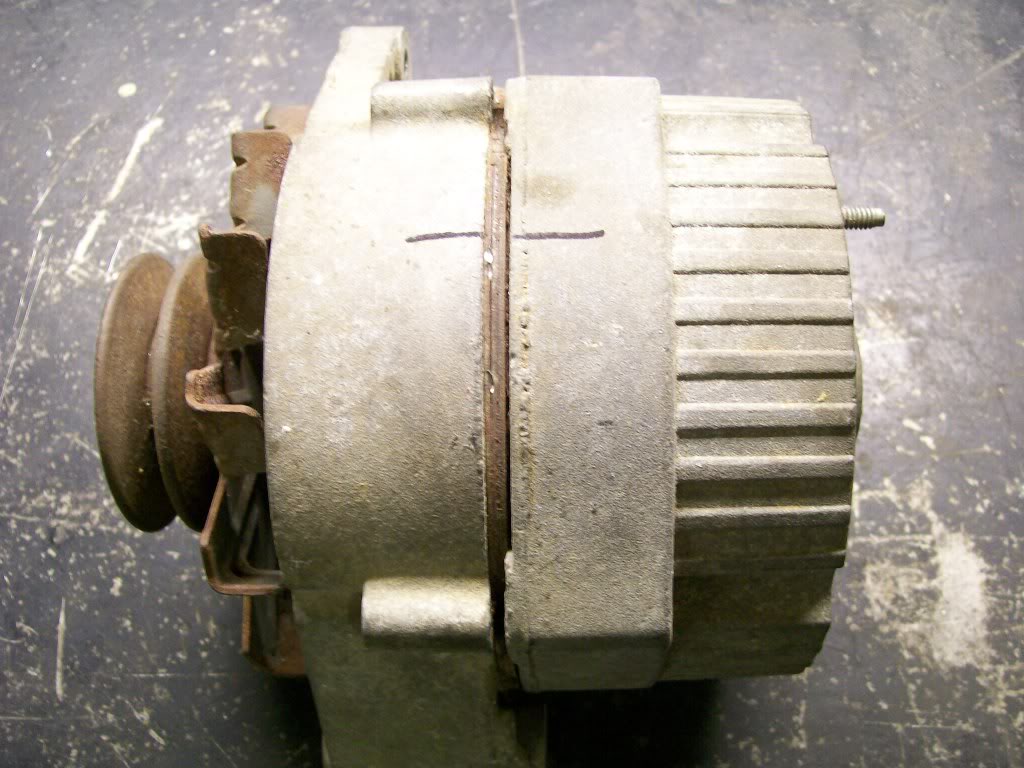
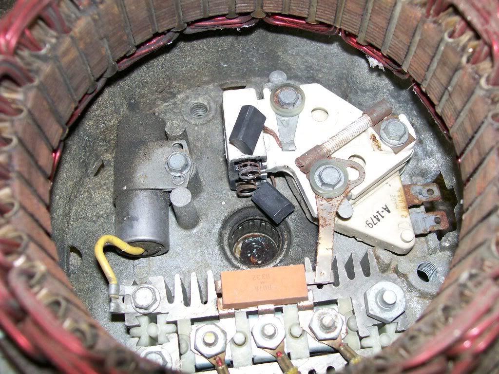
Let's crack this alternator open. Since there are 4 positions available during reassembly it is best to mark the two halves to either get it back as it was if you're rebuilding it, or a reference if you're rotating the back to a different position. Then remove the 4 bolts that hold the 2 halves together.
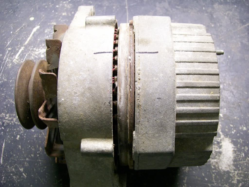
Between the 2 halves you see a darker colored center section, I have to go back to my school days but I believe it's called the stator, the stationary set of windings. When you split the 2 halves this darker center has to go with the back half. Ok, yes, the back can be rotated by removing the bolts and very, very carefully twisting the 2 halves, keeping the center section with the back half. Only problem.. if the alternator is old, due to corrosion the center section won't co-operate with the twist. So disassemble is the best way in this situation.
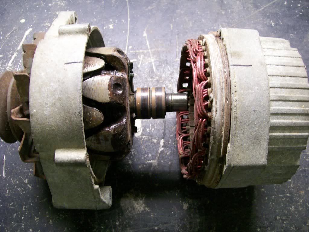
Being this far apart you can see the 2 halves, deeper inside you can see the 2 copper rings that the brushes ride against. It is these brushes that we can't see yet, that will pop out of their holder, these brushes and the springs are the only issue when do this rotation. I'll show resettting the brushes next
time.
2-17-2012
Now that the case is split open and the brushes have popped out of their holder, the brushes have to be put back into their holder before the case halves are put back together again.
Before reassembly I recommend getting some brake cleaner or electric motor cleaner and at least cheaning the brushes. Why?? Looking at the last picture of splitting the case where the two copper rings are located, just after those is the main shaft that goes into the rear bearing. When the brushes leave the copper rings during disassembly they slide across this rear shaft, chances are, the brushes may have gotten grease on them.
Ok, a look at the brushes that are out of the holder.
Down inside there is the voltage regulator, it is located below the brush holder. Later I will show a way to check the regulator with a small screwdriver.
Sorry for the fuzzy picture. You'll notice the plastic holder has a hole in it. This it the hole that a heavy piece of wire will go through. After cleaning the brushes, fit the top brush with it's spring into the holder. Depress the brush and spring far enough so you can slide the wire through the hole and in front of the first brush. Now repeat the process for the second brush, sliding the wire infront of the second brush and through the hole in the other end of the holder. Make sure the wire is long enough to extend far enough to go through the hole in the back of the alternator case. Be sure to leave only about a 1/4" wire yet on the top side of the brush holder. If too much wire is on the top side, it will make contact with the spinning part of the alternator when reassembled. I'd have to check but I believe the spinning part is called the armature.
Fuzzy picture, but it will show the end result of the brushes back in place.
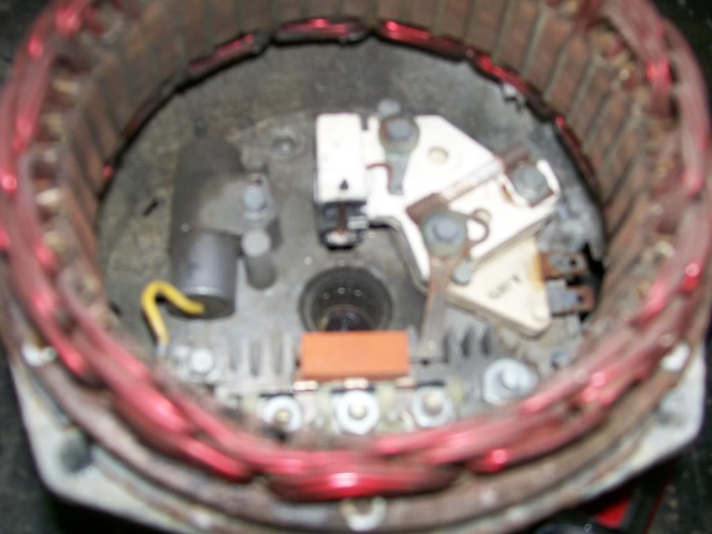
With the brushes inplace, put the case sections back together, make sure the alignment is where you want the wire connections to be, now install the four bolts.
Now turn to the back of the alternator, you'll see the piece of wire you put there holding the brushes. Slowly pull it out of the alternator, you'll notice one brush, then the second brush snap back in place. And your done.
2-19-2012
Earlier I mentioned an easy way to test the voltage regulator that is inside this alternator. I also mentioned all you would need is a small screwdriver.
The designers of this alternator did a great job of creating a way to test this alternator. I once again am sorry for the miserable picture.
Ok, the vehicle is running, and you have a way to get to the back of the alternator with a small screwdriver. Look closely at the miserable picture I have provided. You'll see an arrow to the right pointing to a half moon hole. Just inside the half moon hole is a metal tab. The idea is when the vehicle is running you put the screwdriver into the half moon hole just enough to touch the screwdriver to the metal tab then at the same time touch the side of the screwdriver to the aluminum case.
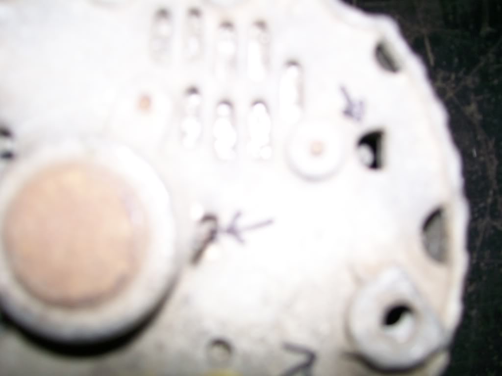
It is designed that when you ground this tab while it's running, it will put the alternator into full charge. Since the alternator will draw close to 4 horse power when at full charge you will immediatly know if it is charging or not.
2-20-2012
hallsofstone, I figure most haven't had to deal with alternator stuff.....yet. but someday, or perhaps in the past, someone turned away from a project due to lack of knowledge. Your knowledge will carry your confidence.
Thanks for checking in.
While working on this '57 I'm not doing any major body modifications. One modification that was done before I ever started on it was the removal of hood and fender emblems. To be honest, sure, it smooths the look, but I still like the look of the old style truck too.
Soooo, I am looking at the original side fender emblems. They were long and oval and had the writing of "Chevrolet 3100" or "Apache 3100". Neither of these did anything for me, so I gonna step out of the box and try my hand at making my own.
I stuck with the same basic size and I wanted to put the size of the 396 engine in there also.
Once again I started with a paper tracing to get a feel of the size on the fender. Once I liked that I cut the main pieces.
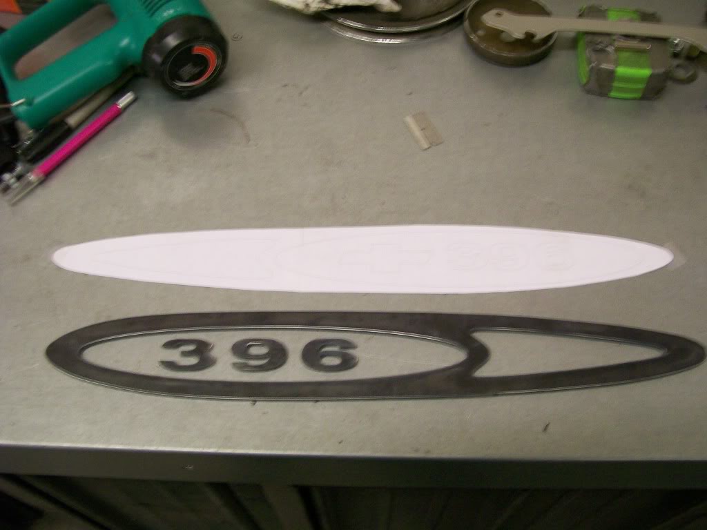
I then cut the base plate that it'll all attach to and I thought the opening that the 396 aren't in needed something so I cut a filler piece for it also.
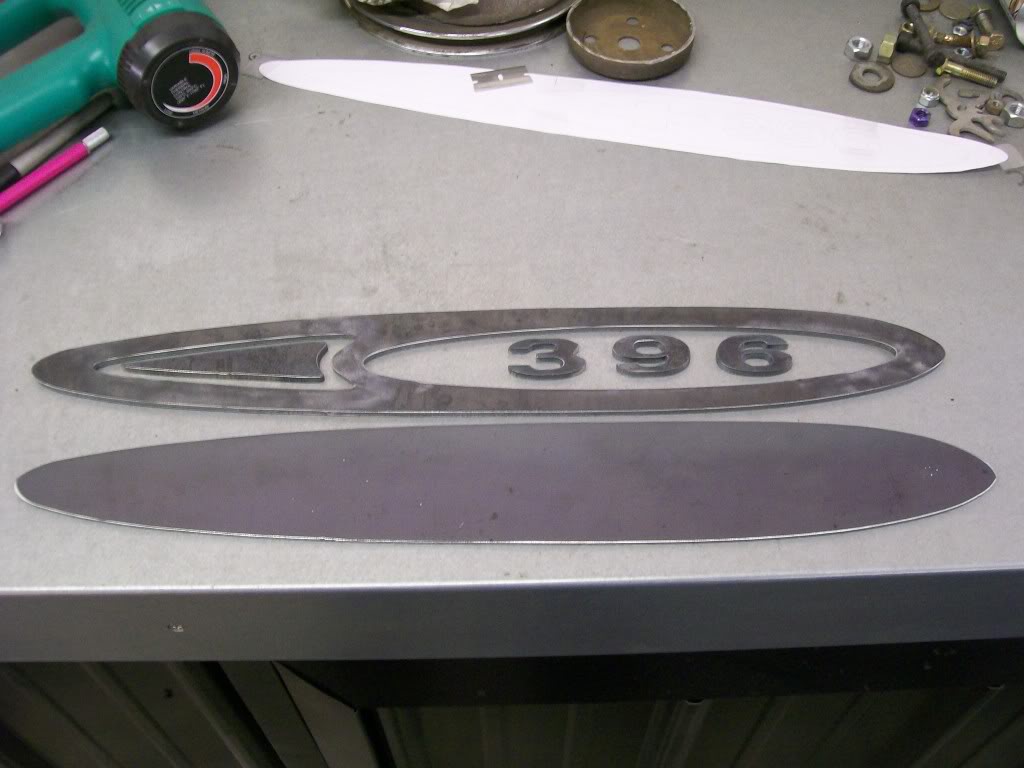
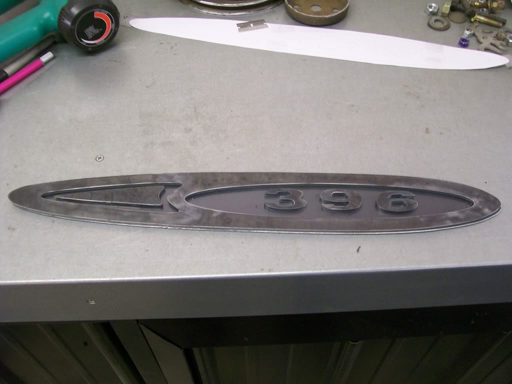
Once all the pieces are assembled, here is the look. I figure I'll drill holes in the backing plate that I'll be able to spot weld the pieces in place from the back side. I'd like to send them off for chrome plating, then I'd like to have the low spots painted to match the color of the truck perhaps.
2-21-2012
I think nickel does look good, I've seen it used. My only problem is I'd have a mixed batch of chrome and nickel. If I get around to the Willys paintwork it would look good there, but I have the same issue, I've collected some brand new chrome emblems already.
On the '57, I'm still focused on getting the engine bay odds and ends taken care of. One thing I've learned over the years is if at all possible, get the odds and ends taken care of, then disassemble and bag, tag and box everything. Assembly after the paint work is so rewarding without scratching the paint.
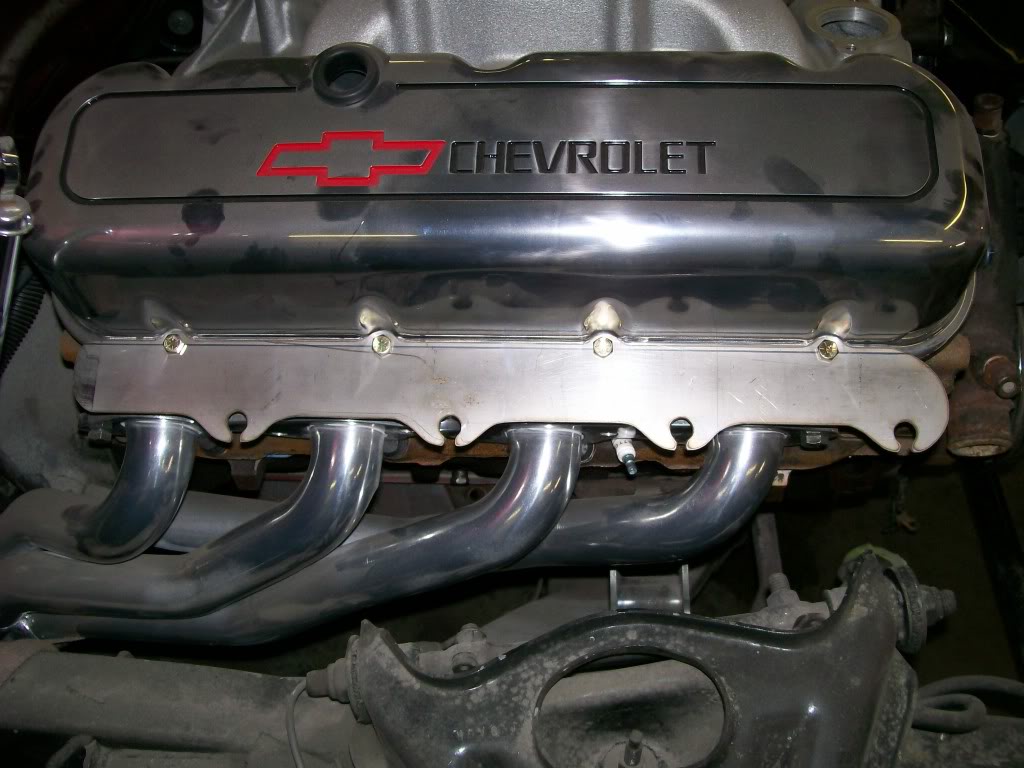
As I mentioned a little while back, I had to add a spacer to the header to get the clearance by the oil filter. The spacer looks like it solved my problem.
Only problem is.... now I have a gasket, spacer, gasket, then header flange. Also the header flange is 3/8 thick, I like the thickness, but before they ceramic coated it, they didn't grind smooth the edge so you can see the cut along the visable edge.
One other issue with the big block chevy is there is about 1 1/2" space between the bottom edge of the valve cover to the header flange. This space usually gets pretty hot and discolors the paint, or burns it off.
I also have an issue with after market spark plug wire holder/separators, they just seem to generic to me.
With one shot I hope to take care of all these issues.
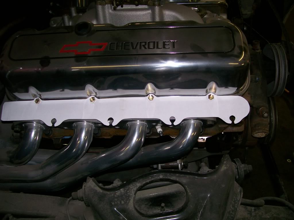
This picture is the first design layout. It is a paper print of a polished stainless steel cover that will support the plug wires perfectly for each cylinder and cover the gasket, spacer, gasket look on the driverside and, cover the area that the paint looks bad after a while.
This paper cutout is to ensure I have all the valve cover holes and the plug wire grips in the right places before the stainless cut.
I trimmed down from the paper cutout on the computer and made the cut with 1/16" stainless. Rather dull at the moment, and the rust spot is just a stain from something else resting on the plate of stainless.
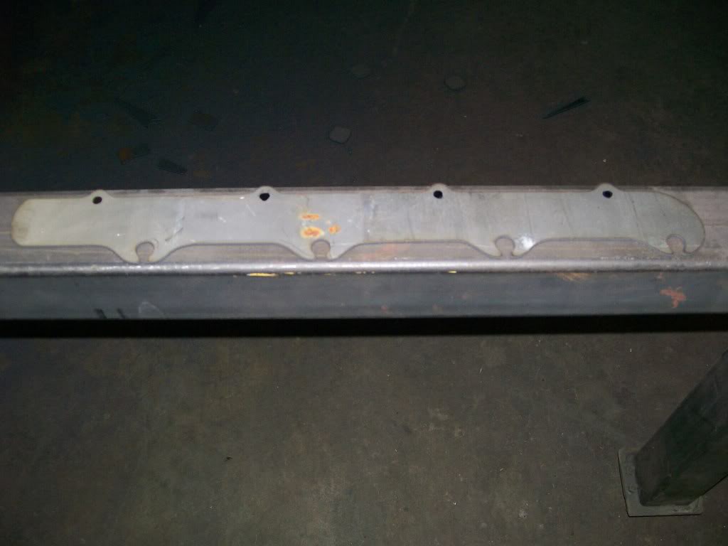
Here it is once I drilled the mounting holes, and no polishing yet. To me it looks a little large, it just covers too much space, but, This surface is going to have the plug wires running down the length of it. Once the plug wires are properly attached, it doesn't look so large and overwelming.