You must be logged in to rate content!
14 minute(s) of a 668 minute read
1-29-2012
Part 2
Compliments of 50wllystrk @ jeepforum.com
1-29-2012
hallsofstone, You are correct, if while doing other projects I do fabricate or rebuild an engine, carb or transmission, this knowledge will still be very applicable to building or restoring Jeep projects.
The reason I have to stop working on the Willys is there is still the possibility of getting some bad weather and anything else I do to it is gonna make it unusable if we get a large snowfall.
One project with the Willys is I do not have a strong crossmember that goes under the engine. The original one was cut out before I bought the truck and I never put a strong one back in. Since the engine has to come out to build a crossmember, I'll wait til spring.
On the '57, the frame is in great shape already. Around 20 years ago before my dad bought it someone swapped the old front straight axle suspension for a elcamino front frame. Whoever did the swap, did a nice job, I have no problem working with it just the way it is.
For the last 20 years he didn't get to enjoy the truck. It had a bad hestitation, the charging system didn't work right, the 327 ended up having a crack in the block, and a few other issues that never provided him with a confidence inspiring drive. This takes us back to when I mentioned the need to know how all the parts on a vehicle work, without this knowledge you'll never feel confident to really enjoy driving something old and classic.
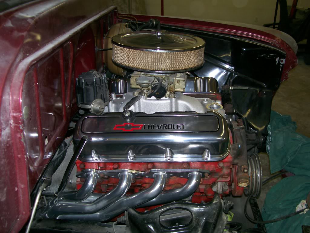
We started from scratch with the body to the powertrain. I had a 396 Chevy so we bored and rebuild it for the truck. I figured I'd fulfill his need for power and there's something about opening a hood and seeing a big block sitting there. So his visual would also be fulfilled.
Of course it is a tight fit, and I took my time fitting it in. My priority was that there had to be space all around the engine to be able to work on it later.
Here is a picture of the engine sitting in place. I was just doing a mock-up so some of the parts are there just for size and dimentions.
1-30-2012
Just did a couple odds and ends on the Willys this weekend. Metal working wise I decided it was time for a Willys key chain. Cut out of 1/8" stainless steel I downsized the emblem image to a key chain size that I used when I made the Willys emblem on the gas cap cover.
Know this, once the plasma cutter is done there is a slight slaggy mess that I have to file and clean before it looks this good, but it's worth the effort.
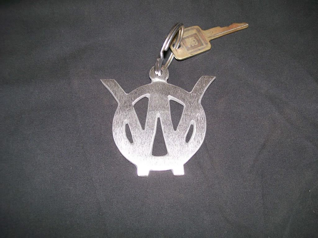
Only problem is the W's have sharp edges. Be careful when in the front pockets.

1-31-2012
On the key rings, I'm gonna see if I make some more in the next couple days. Like I mentioned, after the plasma cutting is done I still have a fair amount of work to do to get it looking like this. In the past I have made key chains. The ones I have made were for commercial use. Basically the vehicle had a single diget number so I cut out the number that represented the vehicle. These are used 6 days a week and still look like the day I made them.
What I'm saying is, being stainless steel they look great, and stay looking great. If I'm gonna sell any of these they're gonna cost around $30.00 a piece with shipping. If your still interested let me know.
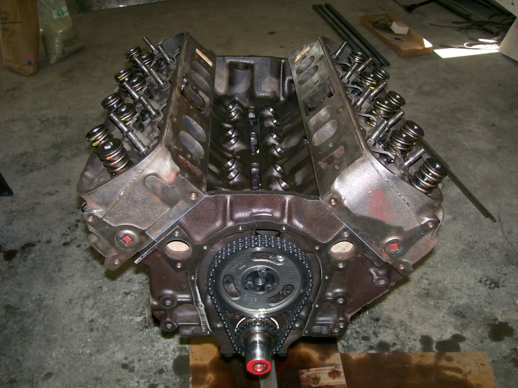
oldtime_ironman, glad to make your day. Since the engine is the focus for a moment, and I figure many here haven't seen much of the insides of an engine, we'll crack it open and take a look see.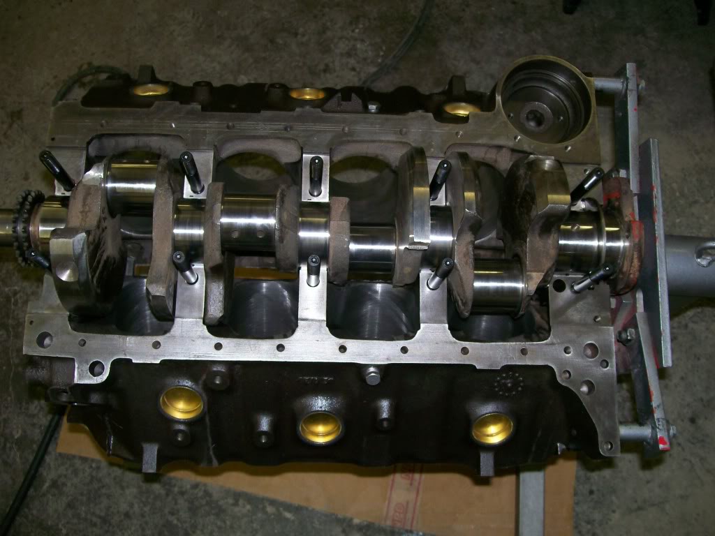
Basically the bottom side of a big block Chevy. One thing we can settle for many is the term "4 bolt main block". This particular engine is a two bolt main. Simply put, you can see the crankshaft in place. Not looking at the very front and the very rear of the crankshaft, but at the center 3 journals where you see a stud pointing upward you see one stud on each side of the crankshaft, this is a two bolt main. If at these center three journals you see two studs perside this would be a "4 bolt main".
I have installed studs vs using bolts. The factory used bolts that's why it's called "4 bolt main". There are kits to where if one feels it is necessary to have 4 bolts/studs you can purchase aftermarket caps with the 4 bolts then you have to drill and thread the block and take it to a machine shop and have machine work done to match the new caps to the block.
Who here has heard of a plastiguage and didn't have a clue as to what they were talking about???
Much simpler than one may think. The clearance between a rod or main bearing to the crankshaft if very, very critical. There is only a couple thousands of an inch that is allowed during assembly. Problem is, once the parts are assembld, there is no way to see the clearance.
This is where a plastiguage comes into play. Plastiguage is nothing more than a string, a little larger in diameter that heavy duty fishing line. This is made from a soft plastic. The way you use it is to assemble the bearings and the crankshaft as usual, put before you put the main and rod bearing caps in place you put a piece of the string between the bearing and the crankshaft. Now tighten and torque to spec. Now untighten and remove the cap. What you will find is that the soft plastic string will be crushed. The more clearance, the less crush. The less clearance, more crush will happen.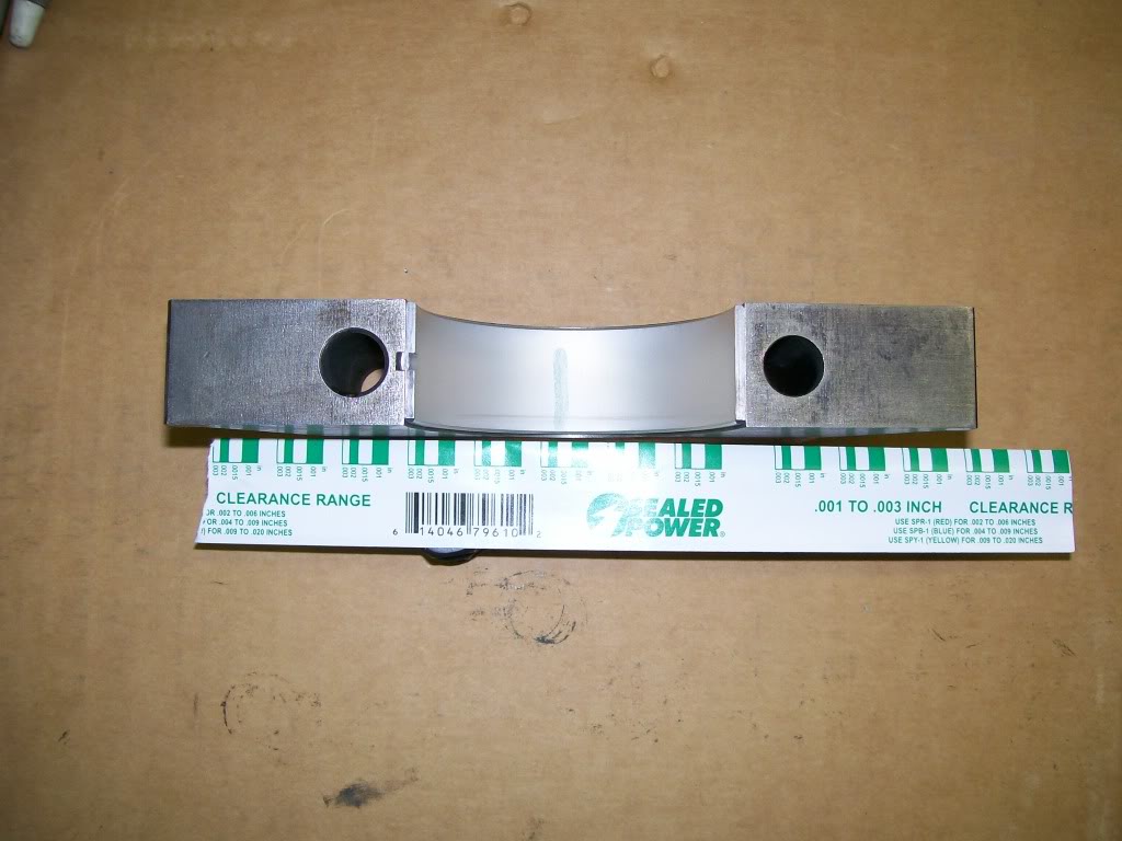
There is a proper spec for every engine. This engine I'm working with is a tight cleance motor. In the above picture look close to the cap and bearing and you'll see a green mark going across the bearing surface. Ok, now using the scale that I have placed by the green mark you'll see the width of the smashed green mark will be close to one of the widths of the scale. In this case the clearance of this bearing to crankshaft is between .0015 to .002 on the scale. Now I know the clearance I have for oil to be able to lubricate the bearing. I also know that the clearance isn't too great of which will cause a knocking sound and also cause a low oil pressure situation.
And one of the engine coming together.
2-14-2012
Hey guys, everything's ok. I've been catching up on odds and ends.
I got to put the Willys to work last night. We got about 5 or 6 inches of snow yesterday. On my way home my neighbor slid off the road and got stuck. Hooked up the Willys, yes, using the hooks that I covered when I showed making the bumper mounts. He liked the convience of the hooks ready for service. Minutes later, he was unstuck and I was heading home, the old truck,62 years old and still yanking vehicles out of the ditch, how cool.
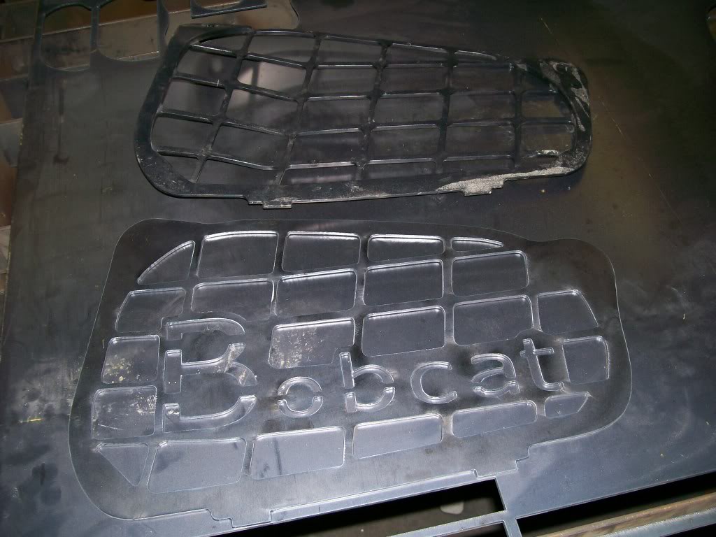
Had another neighbor who brought me a plastic side vent cover off a Bobcat. The cover is close to the track and a branch got stck between the track and the vent cover. He asked if rather than going to Bobcat for a new one, if I could make one. I still need to drill a couple holes and paint, here it is with a slight change. He already has seen it and I got a thumps up.
For reasons just as the snow we just got, I don't want to get deeper into the Willys, so it will sit ready for service for a while yet.
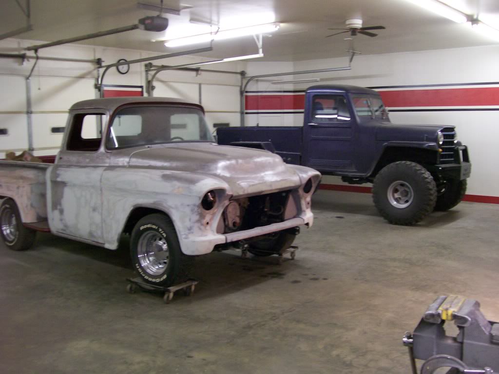
Now the Willys sits where the '57 Chevy was and the '57 Chevy sits where the Willys was. They both look good sitting in the shop.
Although the '57 has a fair amount of body filler, most is just a skin coat to smooth the metal. The nice thing about this Chevy is the body is nearly rust free, this is great! The truck spent most of it's life on a farm in Texas so it had it's share of small dents a dings. I perfer this rather than rust holes and rotted sections to replace. Once the weather turns warm I'll get the base primer on the truck and it should look good.
Til then I want to get the 396 fitted in place. I'm happy with the motor location, I got that settled about a year ago. Now I'm dealing with all the front pulleys. I want to keep the pulleys as close to the block as I can, there's not alot of space between the engine and the radiator. I am using a dual electric fan, the idea being... with one fan blade, the electric motor is in the center, right where the water pump hub is. By using 2 electric fan blades, the center is more open for the water pump hub to have plenty of space.
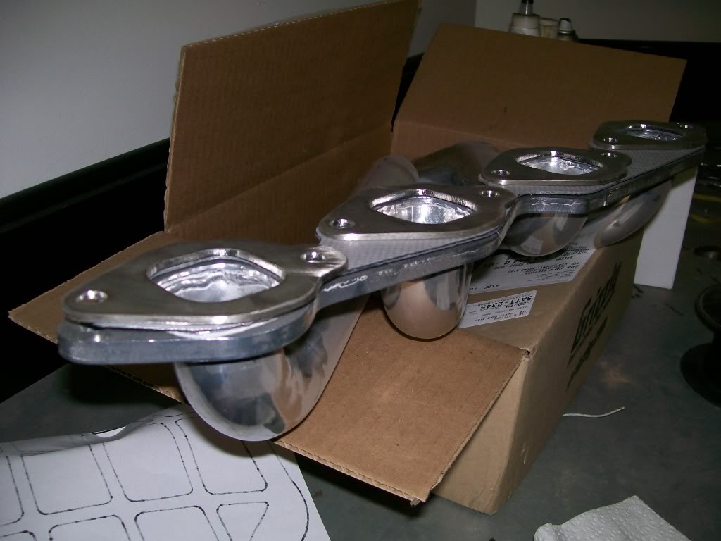
Next up is exhaust headers. No problem on the passenger side. The drivers side needs the header moved out from the engine about 3/16". It's a long story but the outlet is too close to the oil filter. Soooo, I made 1/8" stainless steel spacers. These along with one more gasket will give me the spacing I need. Here are the spacers.
oldtime_ironman, the engine you describe in your last post sounds very close to mine. I did have it bored to a 402, and I do have the oval port heads. I worked the intake ports just before the valve seats to help the flow before they were assembled. I also have the high rise intake and HEI ignition. I used a comp cams 282 camshaft, should have a nice sound at idle which will require a stall speed converter, but I'm looking for the aggressive sound. I can't wait to hear it run.
For the rest of you, buying me a lifetime membership, wow. I suppose I have no idea of who or how many have kept up with this thread. I'm hoping it's been entertaining as well as a good learning. I've down or up loaded a few pics of the '57 issues, including rotating the back of the very commom GM alternator. Guaranteed if you're gonna do a build, this is the first choice alternator and to know something about it will help.
2-15-2012
I mentioned the usage of the Gm/Delco alternator. I doesn't much matter what your building, this is the design that will come into the equation sooner or later.
Go to Jegs or Summit racing and you'll find this alternator as a 100 amp output availability with only one wire attached to it. There is no need for an external regulator since it is also inclosed inside the alternator.
It has a couple different chioces for the pulley. There are single groove and double groove, both with different diameters.
There is one thing that does occasionally need changing and that is the location of the wire hookup.
There are 4 different locations available but the case has to be split to rotate the back to achieve the 4 locations. As with anything you disassemble the first time, the fear of what might spring apart as you disassemble becomes forefront.
The reason for the rotation is there may be a time that the wire outlets run directly into a valve cover, a bracket, or just to be able to hide the wiring for a nice clean look when done.
Also, there may some who are reading this knowing you can rotate the back by removing the case bolts and very causiously rotating the back without disturbing the brushes. Yes, in the right situation you can, but there'd be no learning.
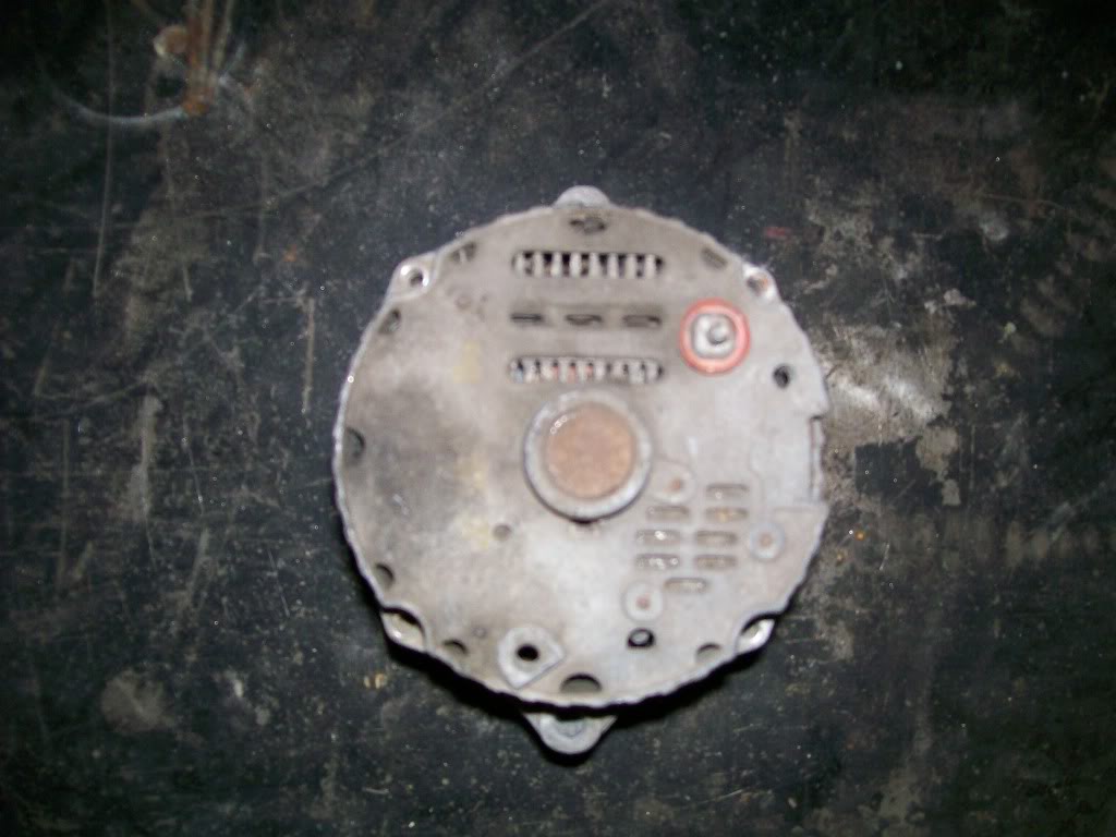
For the mock-up of this '57 Chevy I'm using an old alternator from my inventory, no sense using new parts for mock-up.
When I mount this alternator the extra bolt hole in very back is right against the valve cover, and I want the wiring to face a different direction.
In this second picture the back has been rotated to where I need it to be. One arrow is pointing to the bolt hole that was up against the valve cover.
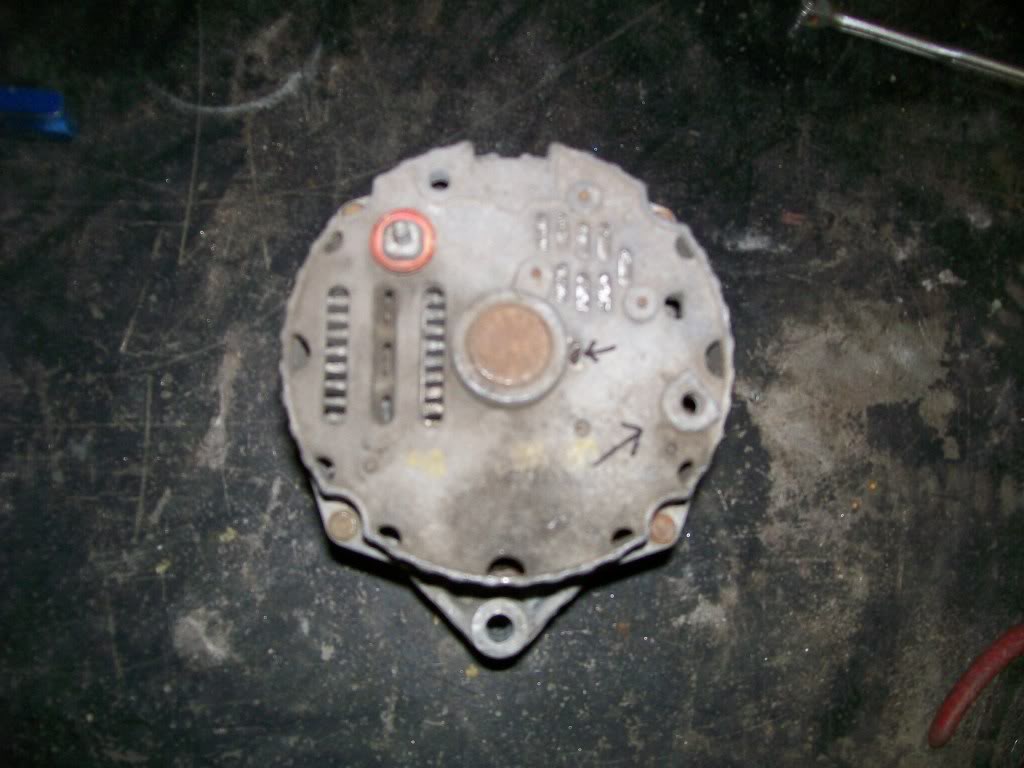
The second arrow pointing towards the center of the alternator, if you look closely, you'll see a heavy piece of wire sticking out. When you split the case, yes, there is a set of spring loaded brushes that pop out of their holder. It is designed that you can compress the springs and brushes back into their holder. Once compressed, slide a piece of wire through a couple holes, then assemble the alternator. Once reassembled, pull this wire out and the brushes snap back into place.
I hope to get some internal pics in the next day or two.
Happy learning.....